evergreen energy homely CEF9H7TC3FE Series User manual

Homely System
Installation Manual
Daikin
Any outdoor unit models from C series onwards
(aside from all ERGA models and CA series ERLQ)
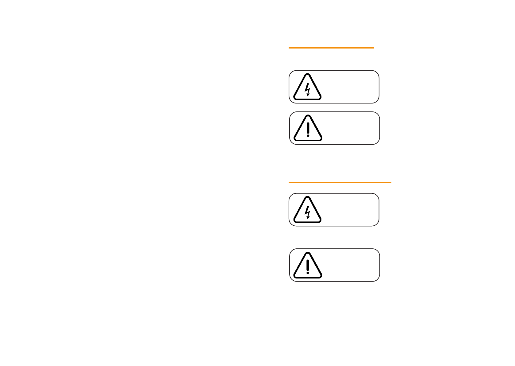
Safety Symbols
Hazards or unsafe practices
that may result in electric
shock and severe personal
injury or death.
The following symbols are used in this manual.
Hazards or unsafe practices
that may result in severe
personal injury or death.
Safety Information
Installation by unqualified persons may result in product
malfunction, electric shock or fire.
The installation must be performed in accordance with
the installation instructions before energising.
Incorrect installation of equipment may result in electric
shock or fire.
DANGER
WARNING
Before proceeding, ensure
that all power supplies in the
property are isolated. Failure
to isolate the power supply
may result in electric shock,
fire or death.
All electrical works must be
conducted by a qualified
technician and must comply
with local regulations.
DANGER
WARNING

1
Contents
22Installation Requirements
44Pre-Installation Checks
55Installer’s Notes
66Step 1: Install the Modbus Adapter
88 Step 2: Connect the Homely Hub
1010 Step 3: Connect the Power Supply
1111 Step 4: System Configuration
1212 Specifications
1414 Declarations of Conformity
About this Manual
This manual has been developed to make installation of the
Homely system a straightforward process.
Follow the steps illustrated in the following pages to ensure
that the Homely device is installed safely and correctly.
Scan the QR code below to visit our YouTube channel where
you will nd further information about Homely, as well as
various installation how-to videos.
We welcome your feedback! Please send all comments to
homely@evergreenenergy.co.uk.

2 3
Installation Requirements
HOMELY NODE
HOMELY HUB
Items Supplied
2 X CRIMP
FERRULE
STICKY PAD
HOMELY
INSTALLER
APP
BELDEN 8723 OR STRANDED
CAT-5 RECOMMENDED
DATA CABLE
Items Required But Not Supplied
Tools Required
CRIMP TOOL
WIRE
STRIPPERS
MULTIMETER
SCREWDRIVERS
PLIERS
MODBUS
ADAPTER
5V POWER
SUPPLY
15V POWER
SUPPLY
120-OHM
RESISTOR
NODE STICKER

4 5
Pre-Installation Checks
Before starting the Homely installation, ensure that the
heat pump has been installed in accordance with the
manufacturer’s instructions.
Use this space to record any
observations about the installed system.
Installer’s Notes

6 7
Install the Modbus Adapter
The Daikin controller is connected to the outdoor unit via
a 2-wire P1/P2 connection as shown below. Optionally,
a wired thermostat may also be connected via P1/P2,
extending the chain of devices.
Mount the Modbus adapter unit near the tank.
If no thermostat is connected, connect the Modbus adapter
P1/P2 terminals to the P1/P2 terminals in either the outdoor
unit or the controller.
If a thermostat is connected, connect the Modbus adapter
P1/P2 terminals to the P1/P2 terminals in either the outdoor
unit or the thermostat.
STEP 1:
P1/P2 Connection
Outdoor Unit
Thermostat
(optional)
Controller
Connect to the P1/P2 terminals
at either end of the device chain.
Refer to Daikin manual for wire
specication.
Connect the 15V power supply to terminals 1 and 2 as
shown above.
On the DCOM’s DIP switches,
set switch 8 ON and the switches
1-7 OFF.
Mount the Modbus
adapter out of the
reach of children.
8 9
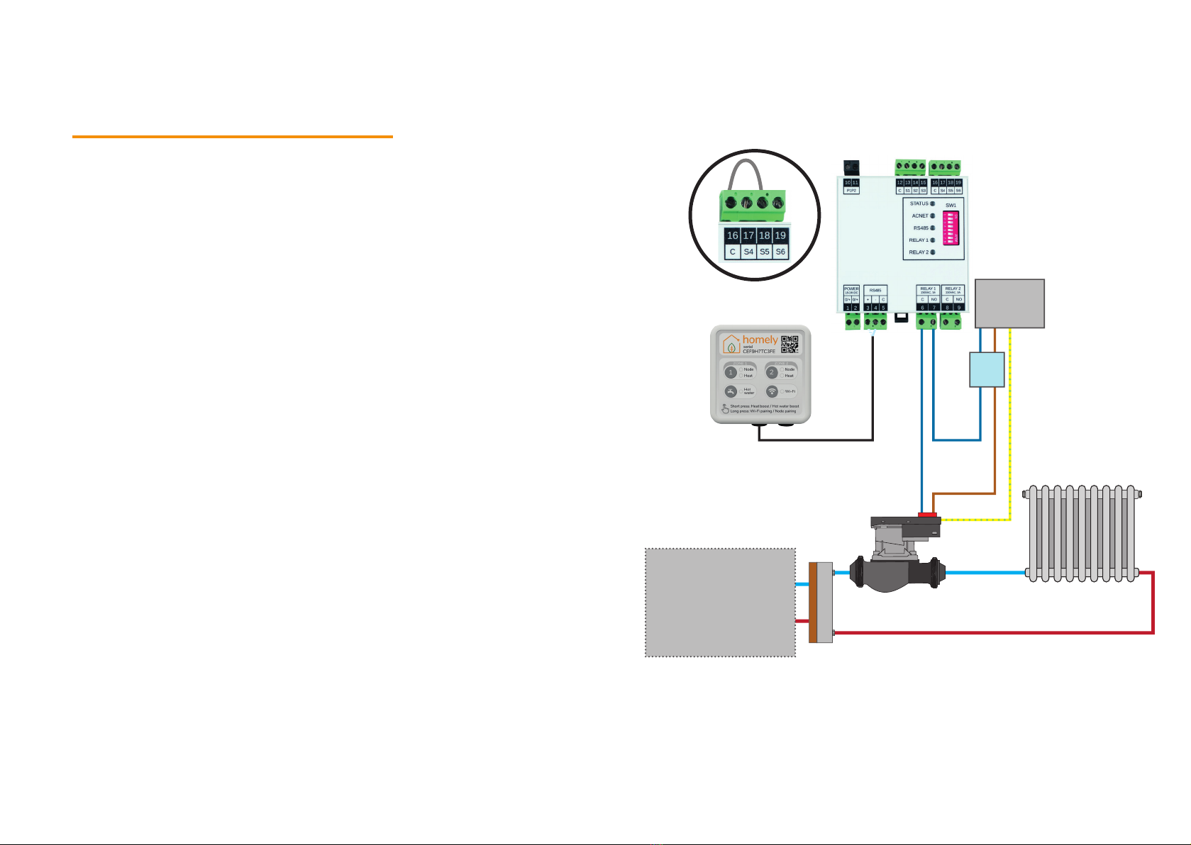
Connect the Homely Hub
For systems with a secondary system pump, use the DCOM
Relay 1 output (terminals 6 & 7) to drive the pump. The
pump must comply with the following requirements:
• The pump must have built-in safety mechanisms so that
it will not operate in the case of a fault condition (e.g.,
overheating).
• The pump must be installed with the necessary external
safety devices (correctly rated fuses/breakers).
• The pump is installed according to the manufacturer’s
instructions.
• The pump must draw no more than 3 amps at maximum
operating power.
DCOM input S5 (terminal 18) must be short-circuited directly
to input C (terminal 15) for correct operation.
An example of the connection into a secondary system is
shown opposite:
STEP 2:
Mains
230V/
240V
Heat
Pump
CB
10 11
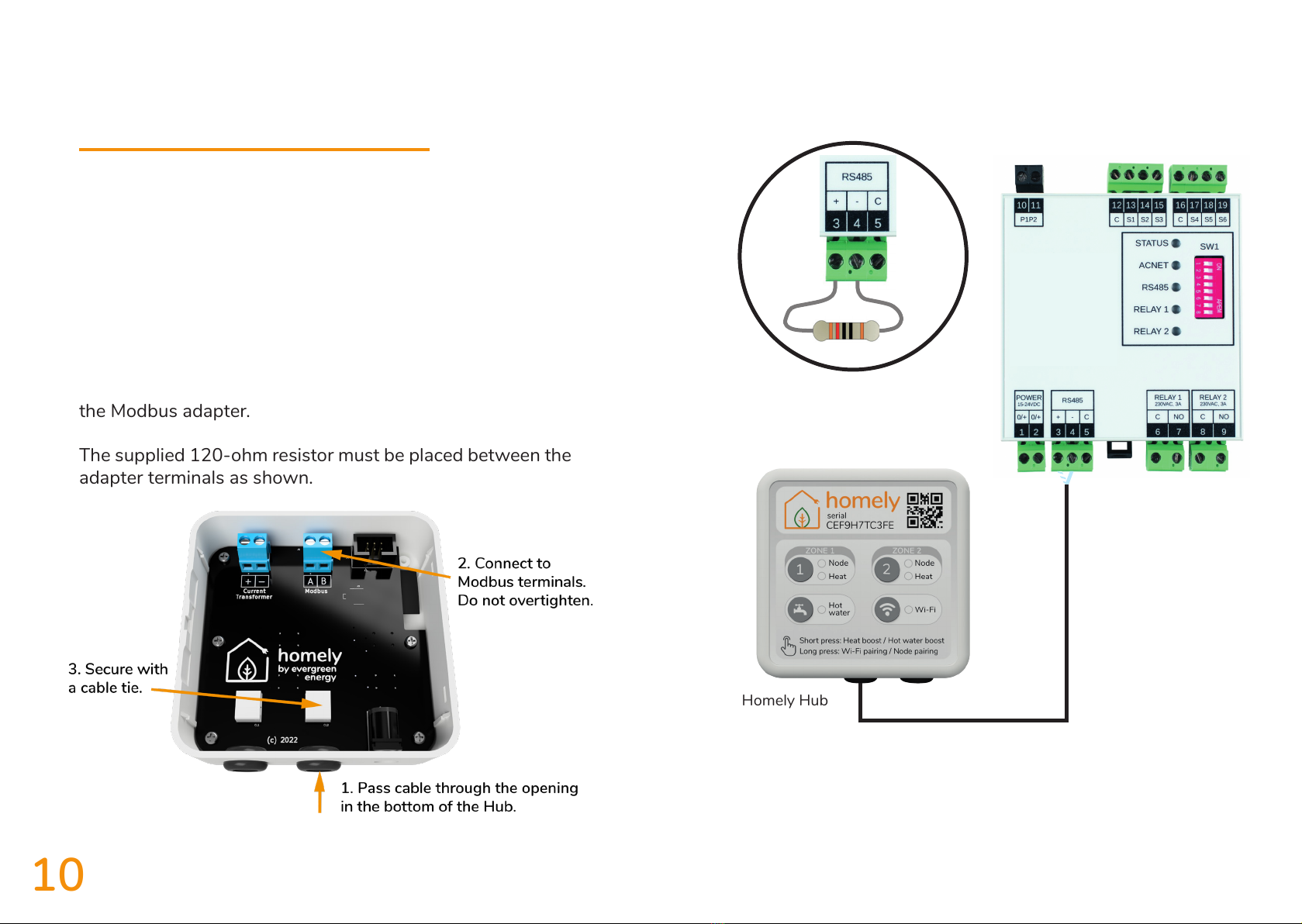
Connect the Homely Hub
Connect the Homely Hub to the Daikin controller/outdoor
unit with data cable. Belden 8723 or stranded Cat-5 are
recommended.
Remove the back of the Homely Hub and identify the
terminals for Modbus connection.
A single twisted pair must be used. Connect the A terminal
in the Homely Hub to terminal 3 on the Modbus adapter.
Connect the B terminal in the Homely Hub to terminal 4 on
the Modbus adapter.
The supplied 120-ohm resistor must be placed between the
adapter terminals as shown.
STEP 3:
Homely Hub
12 13
Connect the power supply to the Homely Hub as shown and
plug into a power outlet.
Plug the Modbus adapter power supply into a power outlet.
Connect the Power Supply
It may be necessary to install a new outlet
on a spur if there is not one within range.
NOTE
STEP 4:
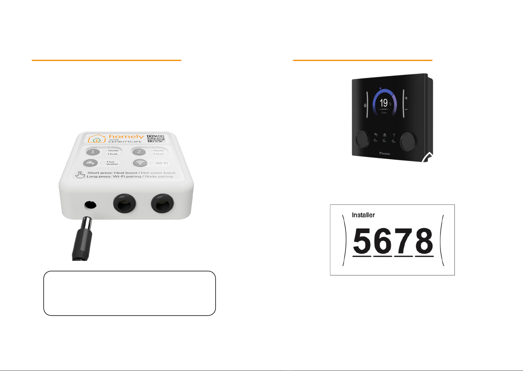
Controller Configuration
STEP 5:
On the controller, scroll to the “User Prole” setting with the
left wheel and select with the left button.
Enter the password, which is 5678 by default, to allow
access to the installer settings. Use the right wheel to
select each number, then conrm with the right button
(inside the right wheel). When all numbers are entered,
press the left button.

14 15
Follow the in-app instructions to connect the Node to the
Hub, connect the Hub to a WiFi network and complete the
Homely conguration.
Contact homely@evergreenenergy.co.uk if you do not have
a login for the Homely Installer App.
System Configuration
Download
the Homely
Installer App
and register
an account
Email
Password
Register New Account
Log in
Reset Password
STEP 6:
Go to “Installer Settings” and select with the left button,
then “Conguration Wizard”, then “OK”.
In the wizard, choose your preferred language, then set
the time and date. Use the right wheel to select individual
parameters and the right button to conrm them, then the
left button to conrm all time & date settings.
The controller will now be on the “System” menu; press the
left button. This will bring up the “Backup Heater” menu;
press the left button again.
The controller will now show the “Main Zone” menu. Select
your emitter type and press the right button. Set “Control”
to “Leaving Water” and press the right button. “Set Point”
to “Fixed” and press the right button. Conrm all the
settings on this menu with a left button press.
Conrm “Tank” setting “Heat Up Mode” is “Reheat Only”
and press left button.
Finally, conrm the setup with OK.
Wait for new conguration to be applied to the heat pump
and then the DCOM unit.
For more information on the settings and menu navigation,
please see your heat pump’s installation manual.

16 17
Specifications
Homely Node
1716
Homely Hub
Dimensions:
86 x 86 x 25mm
Communication protocols:
Proprietary 868MHz
Bluetooth v4.2
WiFi 802.11 b/g/n
Power:
5V 1.0A
Recommended operating conditions:
10 to 35 ºC
Dimensions:
43 x 43 x 14mm
Communication protocols:
Proprietary 868MHz
Power:
Internal: CR2450 battery
Temperature Sensor Accuracy:
Internal: 0.4 ºC (max), 10 to 85 ºC
Humidity Measurement:
Accuracy: 2% Relative Humidity (RH)
Range: 0% to 100% RH
Recommended operating conditions:
10 to 35 ºC

18 19
UK Declaration of Conformity
This UK Declaration of Conformity is issued under the sole
responsibility of Evergreen Energy Limited. Registered
address: Evergreen Energy, The Edge Business Centre, The
Edge, Clowes Street, Manchester M3 5NA. Contact details:
Email: homely@evergreenenergy.co.uk
Web: www.homelyenergy.com
Phone: 0161 818 9005
Evergreen Energy Limited declares that the Homely system
consisting of Homely Hub and Homely Node v2 is in
compliance with the essential requirements of the following:
Radio Equipment Regulations 2017
Restriction of the Use of Certain Hazardous Substances in
Electrical and Electronic Equipment Regulations 2012
Signed for and on behalf of Evergreen Energy Ltd:
Name: Steve Elliott
Function: Technical Director
Place of issue: United Kingdom
Date of issue: 07/03/2023
Standards applied
Standard Description
ETSI EN 301 489-1
V2.1.1
ElectroMagnetic Compatibility (EMC) standard
for radio equipment and services; Part 1:
Common technical requirements
ETSI EN 301 489-3
V2.1.1
ElectroMagnetic Compatibility (EMC) standard
for radio equipment and services; Part 3:
Specific conditions for Short-Range Devices
(SRD) operating on frequencies between 9 kHz
and 246 GHz
ETSI EN 301 489-17
V3.1.1
ElectroMagnetic Compatibility (EMC) standard
for radio equipment and services; Part 17:
Specific conditions for Broadband Data
Transmission Systems
EN 55032:2012 Electromagnetic compatibility of multimedia
equipment – Emission requirements
EN 55035:2017 Electromagnetic compatibility of multimedia
equipment – Immunity requirements
EN 61326-1:2013 Electrical equipment for measurement, control
and laboratory use – EMC requirements – Part
1: General requirements
EN 62368-1:2020 Audio/video, information and communication
technology equipment – Part 1: Safety
requirements

20 21
EU Declaration of Conformity
This EU Declaration of Conformity is issued under the sole
responsibility of Evergreen Energy Limited. Registered
address: Evergreen Energy, The Edge Business Centre, The
Edge, Clowes Street, Manchester M3 5NA, UK. Contact
details:
Email: homely@evergreenenergy.co.uk
Web: www.homelyenergy.com
Phone: +44 (0)161 818 9005
Evergreen Energy Limited declares that the Homely system
consisting of Homely Hub and Homely Node v2 is in
compliance with the essential requirements of the following:
Directive 2014/53/EU (Radio Equipment)
Directive 2011/65/EU (RoHS)
Signed for and on behalf of Evergreen Energy Ltd:
Name: Steve Elliott
Function: Technical Director
Place of issue: United Kingdom
Date of issue: 07/03/2023
Standard Description
ETSI EN 301 489-1
V2.1.1
ElectroMagnetic Compatibility (EMC) standard
for radio equipment and services; Part 1:
Common technical requirements
ETSI EN 301 489-3
V2.1.1
ElectroMagnetic Compatibility (EMC) standard
for radio equipment and services; Part 3:
Specific conditions for Short-Range Devices
(SRD) operating on frequencies between 9 kHz
and 246 GHz
ETSI EN 301 489-17
V3.1.1
ElectroMagnetic Compatibility (EMC) standard
for radio equipment and services; Part 17:
Specific conditions for Broadband Data
Transmission Systems
EN 55032:2012 Electromagnetic compatibility of multimedia
equipment – Emission requirements
EN 55035:2017 Electromagnetic compatibility of multimedia
equipment – Immunity requirements
EN 61326-1:2013 Electrical equipment for measurement, control
and laboratory use – EMC requirements – Part
1: General requirements
EN 62368-1:2020 Audio/video, information and communication
technology equipment – Part 1: Safety
requirements
Harmonised standards applied
Hub v3 Rev 1.4 June 2023
Printed on FSC-certied paper
Table of contents
Popular Switch manuals by other brands

Delta Controls
Delta Controls GR2 Installation, operation & maintenance instructions

Dell
Dell PowerConnect W-IAP175P manual

H3C
H3C S9500 Series Command manual

Watts
Watts AMES C200 Series Wiring instructions

Aruba
Aruba 6400 Series Installation, Safety, and Regulatory Information

Acuity Brands Lighting
Acuity Brands Lighting Pathway VIA 12 Series user guide


TRENDnet
TRENDnet TEG-S5 Quick installation guide

Fujitsu
Fujitsu XG2600 Series Hardware guide

SJE Rhombus
SJE Rhombus VERTICALMASTER Installation and operating instructions

FOLSOM
FOLSOM ScreenPro SPR-2000 Installation and operator's manual

Extreme Networks
Extreme Networks EAS 200-24p Switch Hardware installation manual

Westermo
Westermo SD-300 Series installation manual