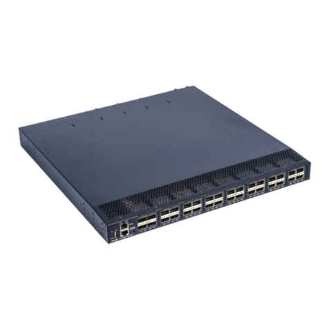
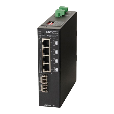
Acuity Brands Lighting Pathway VIA 12 Series User manual

User Guide
REV 1.0
June 2020 Pathway Connectivity
1439 17 Ave SE • Calgary, AB • T2G 1J9
+1 (403) 243-8110
ETHERNET
SWITCHES
6750, 6750-P, 6752-P, 6754-P Models
Running firmware 5.X
TM

Copyright © Pathway Connectivity
A Division of Acuity Brands Lighting Canada (“Pathway”) and its licensors.
All rights reserved.
This software and, as applicable, associated media, printed materials and “on-line” or electronic
documentation (the “Software Application”) constitutes an unpublished work and contains valuable trade
secrets and proprietary information belonging to Pathway and its licensors.
WARNING ABOUT INSECURE PROTOCOLS
Enabling an open protocol that does not use encryption or authentication - these protocols could be
eavesdropped or spoofed by malicious parties. You are strongly encouraged to secure access to your
network, both physically and technologically. To continue, you must acknowledge that you have read
this statement and accept these risks.

CONTENTS
ABOUT VIA ETHERNET SWITCHES..................................................1
INSTALLATION INSTRUCTIONS........................................................1
PANEL LAYOUTS ................................................................................3
FRONT PANEL........................................................................................3
MODEL 6750, 6750-P �������������������������������������������������������������������������������������������3
MODEL 6752-P, 6754-P����������������������������������������������������������������������������������������3
REAR PANEL ..........................................................................................3
MODEL 6750���������������������������������������������������������������������������������������������������������3
MODEL 6750-P �����������������������������������������������������������������������������������������������������4
MODEL 6752-P �����������������������������������������������������������������������������������������������������4
MODEL 6754-P �����������������������������������������������������������������������������������������������������4
SFP+ PORTS���������������������������������������������������������������������������������������������������������5
opticalCON PORTS ����������������������������������������������������������������������������������������������5
POWER CONNECTIONS ��������������������������������������������������������������������������������������5
CONFIGURATION ...............................................................................5
SECURITY...............................................................................................6
BACKGROUND INFORMATION ���������������������������������������������������������������������������6
WHAT THIS MEANS TO YOU �������������������������������������������������������������������������������6
INTRODUCING SECURITY DOMAINS �����������������������������������������������������������������7
CREATING A SECURITY DOMAIN �����������������������������������������������������������������������8
ADMINISTERING A DOMAIN �����������������������������������������������������������������������������10
LOCAL SECURITY - USING VIA WITHOUT PATHSCAPE ���������������������������������12
RECOVERING A DOMAIN ����������������������������������������������������������������������������������13

RETAINING DEVICE SETTINGS FROM UNKNOWN DOMAINS������������������������14
USING OLDER VERSIONS OF PATHSCAPE WITH NEW DEVICES������������������14
SOFTWARE (PATHSCAPE) CONFIGURATION ...................................15
NETWORK SETUP����������������������������������������������������������������������������������������������15
DEVICE PROPERTIES ����������������������������������������������������������������������������������������16
ADVANCED CONFIGURATION���������������������������������������������������������������������������22
PORT PROPERTIES AND CONFIGURATION.....................................32
BASIC PROPERTIES ������������������������������������������������������������������������������������������32
NETWORK PROPERTIES �����������������������������������������������������������������������������������34
VLAN PROPERTIES ��������������������������������������������������������������������������������������������35
NETWORK PROTOCOL SUPPORT��������������������������������������������������������������������35
PoE PROPERTIES (NOT SHOWN ON VIA12 MODEL 6750)������������������������������37
SFP/SFP+ TRANSCEIVER (SFP+ PORTS ONLY) ����������������������������������������������38
UPGRADING DEVICE FIRMWARE......................................................39
FRONT PANEL UI AND MENU .........................................................40
MAIN DISPLAY MESSAGES ................................................................40
USING THE FRONT PANEL UI ............................................................40
MENUS..................................................................................................41
NETWORK SETUP����������������������������������������������������������������������������������������������41
DEVICE INFO/STATUS����������������������������������������������������������������������������������������43
ADVANCED SETTINGS���������������������������������������������������������������������������������������44
PORT STATUS AND CONFIGURATION MENU ��������������������������������������������������55
PORT 13 & 14: CONFIGURATION/STATUS: SFP+ PORTS��������������������������������60
APPENDIX 1: SFP/SFP+ FIBER ADAPTER SELECTION................63
APPENDIX 2: VIRTUAL LOCAL AREA NETWORK (VLAN).............64

DEFINITIONS ������������������������������������������������������������������������������������������������������64
SOFTWARE CONFIGURATION OF VLANs ��������������������������������������������������������64
VLAN GUIDELINES ���������������������������������������������������������������������������������������������64
APPENDIX 3: PLANNING CHARTS .................................................65
VLAN PLANNING CHART�����������������������������������������������������������������������������������65
SWITCH PLANNING CHARTS����������������������������������������������������������������������������67
APPENDIX 4: RING PROTECTION ..................................................69
REQUIREMENTS AND LIMITATIONS�����������������������������������������������������������������69
DEFINITIONS ������������������������������������������������������������������������������������������������������69
APPENDIX 5: RAPID SPANNING TREE PROTOCOL .....................70
APPENDIX 6: QoS SETTINGS ..........................................................71
APPENDIX 7: ELECTRICAL AND COMPLIANCE INFORMATION.72
ELECTRICAL INFORMATION..............................................................72
MODEL 6750�������������������������������������������������������������������������������������������������������72
MODEL 6750-P ���������������������������������������������������������������������������������������������������72
MODEL 6752-P, 6754-P��������������������������������������������������������������������������������������72
COMPLIANCE ......................................................................................72

VIA12 [6750, 6750-P, 6752-P, 6754-P] - Manual REV 1.0 • June 2020
1
ABOUT VIA ETHERNET SWITCHES
VIA™ Gigabit Ethernet Switches are designed for live entertainment Ethernet systems, including audio, video and DMX-over-
Ethernet networks. This manual covers models 6750, 6750-P, 6752-P and 6754-P.
VIA Ethernet Switches are intended specifically for signal routing between Pathport DMX-over-Ethernet gateways, or similar
equipment, and Ethernet-aware lighting and audio control products, such as consoles and controllers and end equipment. A
VIA is a routing device and is not a source of the control protocols or the data being passed. Switches only provide management
control over the data path.
The VIA12 family is easily configured and upgraded using the freely available software tool, Pathscape. They are also
configurable using the Front Panel UI, which consists of the LCD and rotary pushbutton encoder.
IMPORTANT: VIA model 6750 does not provide hardware support for IEEE 802.3af Power-over-
Ethernet (PoE). It does not provide a way to connect an external PoE supply. VIA models
6750-P, 6752-P and 6754-P feature an integrated 100W PoE supply for powering compatible
external devices.
If you connect PoE-enabled devices to a 6750 they will not receive power.
INSTALLATION INSTRUCTIONS
VIA switches are intended for desktop use, or to be mounted in a standard 19” equipment rack, using the integral rack ears
(model 6752-P and 6754-P) or the included rack ear accessories (models 6750 and 6750-P). Use the included hex bolts to
attach the rack ears to the enclosure.
Rack ear accessories included with the 6750 and 6750-P for attaching unit to 19” equipment rack
Truss-mount adaptors (P/N 9003) and wall-mount kits (P/N 9002) are available as accessories.
POE
LINK/ACT
PORT 1 PORT 2 PORT 3 PORT 4 PORT 5 PORT 6 PORT 7 PORT 8 PORT 9 PORT 10
TM
POE
LINK/ACT
PORT 1 PORT 2 PORT 3 PORT 4 PORT 5 PORT 6 PORT 7 PORT 8 PORT 9 PORT10
TM
#9002 Wall-mount Kit #9003 Truss-mount Kit

REV 1.0 • June 2020 2
VIA12 [6750, 6750-P, 6752-P, 6754-P] - Manual
All VIA Switches are intended for installation in a dry, indoor location. Ambient operating conditions are 14°F to 122°F (-10°C
to 50°C); 5-95% relative humidity, non-condensing.
Warning: The AC socket outlet shall be installed near the equipment and shall be easily
accessible.
Warning: This equipment relies on building installation primary overcurrent protection.
Warning: Except for the chassis plug marked for AC input, all ports on the VIA12 are intended
for low voltage and/or data lines only. Attaching anything other than low voltage sources to the
data ports may result in severe equipment damage, and personal injury or death.

VIA12 [6750, 6750-P, 6752-P, 6754-P] - Manual REV 1.0 • June 2020
3
PANEL LAYOUTS
FRONT PANEL
MODEL 6750, 6750-P
POE
LINK/ACT
PORT 1 PORT 2 PORT 3 PORT 4 PORT 5 PORT 6 PORT 7 PORT 8 PORT 9 PORT 10
TM
Backlit LCD
Rotary Encoder
Turn to Highlight
Push to Select RJ45 etherCON
Connector
Amber LED
(Link Active)
Green LED (PoE Active)
(6750-P model)
MODEL 6752-P, 6754-P
Backlit LCD
Rotary Encoder
Turn to Highlight
Push to Select
RJ45 etherCON
Connector
Amber LED
(Link Active)
Green LED
(PoE Active)
REAR PANEL
MODEL 6750
Risk of electric shock.
Disconnect power
before opening.
Risque de decharge
electrique. Debrancher
le pouvoir avant
d'ouvrier.
ATTENTION
100-240 VAC
50/60Hz 0.3A MAX
Female RJ45 etherCON Connector
Push tab to release cable
IEC Power Connector for
100 - 240 VAC Input
Link/Status LEDs for
SFP+ ports
2x SFP+ ports for fiber
transceivers or copper
Direct-Attach cables

REV 1.0 • June 2020 4
VIA12 [6750, 6750-P, 6752-P, 6754-P] - Manual
MODEL 6750-P
Risk of electric shock.
Disconnect power
before opening.
Risque de decharge
electrique. Debrancher
le pouvoir avant
d'ouvrier.
ATTENTION
100-240 VAC
50/60Hz 1.3A MAX
2x SFP+ ports for fiber
transceivers or copper
Direct-Attach cables
IEC Power Connector for
100 - 240 VAC Input
Link/Status LEDs for
SFP+ ports
Female RJ45 etherCON Connector
Push tab to release cable
MODEL 6752-P
PORT 11
PORT 12
PORT 13
PORT 14
MULTIMODE
FIBER
AUXILIARY
GIGABIT
ETHERNET
AC INPUT
MAX 10A
AC THRU
opticalCON DUO
connectors for Multimode fiber
RJ45 etherCON
Connectors powerCON Connector
for AC Thru
powerCON Connector
for AC Input
MODEL 6754-P
PORT 11
PORT 12
PORT 13
PORT 14
MULTIMODE
FIBER
AUXILIARY
GIGABIT
ETHERNET
AC INPUT
MAX 10A
AC THRU
opticalCON QUAD
connectors for Multimode fiber
[Primary (top) pair connected only]
RJ45 etherCON
Connectors powerCON Connector
for AC Thru
powerCON Connector
for AC Input

VIA12 [6750, 6750-P, 6752-P, 6754-P] - Manual REV 1.0 • June 2020
5
SFP+ PORTS
Models 6750 and 6750-P have two SFP+ compatible ports on the rear of the device. These require the user to provide an
SFP or SFP+ fiber transceiver to allow connection to fiber networks. See Appendix 1: SFP+ Fiber Adapter Selection for
more information on selecting a fiber transceiver.
The user may also use SFP+ Direct Attach cables, both active and passive. This is often the easiet and lowest-cost way to
connect multiple switches together, if they are close together in the same enclosure or rack.
opticalCON PORTS
Models 6752-P and 6754-P have opticalCON DUO and opticalCON QUAD ports, respectively, for multimode fiber cables
installed instead of SFP+ ports. Additional SFP+ transceivers are not required.
POWER CONNECTIONS
The IEC power plug or powerCON AC Input plug may be connected to an AC power source with a voltage between 100
and 240VAC, either 50 or 60 Hz.
Models 6752-P and 6754-P have an additional powerCON THRU connector to simplify mains power connections in a rack.
DO NOT EXCEED 10A DRAW ON THE FIRST SWITCH. The powerCON THRU jumper cable is not provided.
CONFIGURATION
Models 6750, 6750-P, 6752-P and 6754-P may be configured from the front panel interface using the LCD and rotary
pushbutton encoder. However, we recommend using our free software tool, Pathscape, if possible. To download Pathscape,
visit the Pathway website at https://www.pathwayconnect.com/index.php/products/software/176-pathscape and click the
download link for the appropriate operating system. Use the QR Code below to visit the download page.
For instructions on how to set properties and send transactions to devices, refer to the Pathscape manual.
For instructions on using the LCD and encoder to navigate the switch menus, see the Front Panel UI and Menu section.

REV 1.0 • June 2020 6
VIA12 [6750, 6750-P, 6752-P, 6754-P] - Manual
SECURITY
BACKGROUND INFORMATION
On January 1, 2020, California will be the first state to enforce cybersecurity and IoT related legislation. Oregon, New
York and Massachusetts are following suit. California’s law is Title 1.81.26 “Security of Connected Devices” and mandates
that we equip our products with security features that are appropriate to the nature and function of the device. By law,
this encompasses all products that are assigned Internet Protocol addresses which can connect to the Internet directly or
indirectly. Pathway Connectivity, a division of Acuity Brands, will only ship compliant devices regardless of the jurisdiction into
which they are sold.
The law requires us to either supply a unique password for our products (see Local Security below) or requires the users
to change the password before being able to use it (See Creating a Security Domain below). With Pathscape V3, we
provide features that protect our products from unauthorized access or use by enforcing passwords. Furthermore, Pathway
Connectivity does not collect or store personal information on our devices.
WHAT THIS MEANS TO YOU
1. When using products shipped after January 1, 2020, Pathscape will require a single password to allow configuration of
all the devices on your network.
2. Products shipped before January 1, 2020 will continue to function without passwords using either Pathscape 2 or
Pathscape 3.
3. All products shipped after January 1, 2020 may only be configured using Pathscape 3.
4. Products shipped after January 1, 2020 cannot be downgraded to earlier password-free firmware.
5. Products that are fully configurable from the front panel can create their own unique password. Only with network
configured products will you need to type a password; one password for all devices on the network.
6. You will be encouraged to print or save a recovery key in case you lose the password.
7. If you lose the password and lose the recovery key, you will manually have to factory default each device on the network.
See the resource section of the Pathway website for a comprehensive document describing how to manually factory
default all our devices.
8. The complete network configuration may be saved without a password before factory defaulting devices. Applying the
saved configuration will require a new password to be set for the network.
9. Configuring our devices to receive unsecured protocols such as sACN and ArtNet will require you to accept the risks. See
WARNING BOX regarding unsecured protocols below.
10. Pathway does not store personal information such as names or email addresses on our devices.

VIA12 [6750, 6750-P, 6752-P, 6754-P] - Manual REV 1.0 • June 2020
7
INTRODUCING SECURITY DOMAINS
To simplify the process of managing security on your network, Pathscape 3 introduces the concept of a “Security Domain”.
Below we will describe how to create a Security Domain and add or remove devices from it. In the Device tab of Pathscape
3 there is a new view that shows you the name of the device’s domain and a padlock icon showing its current state.
There are four different ways a device can appear in the Security Domain column.
Red Padlock - Unsecured Device
Any device shipped after January 1, 2020 will have version 5 firmware which includes security. These devices will report
their type, name and firmware version only. All other properties cannot be read until you add them to a Security Domain
(see below on creating domains).
Amber Padlock - Secured Device not in the Current Domain
Devices that have been added to a security domain will appear with an amber padlock. These firmware v5 devices will allow
you to read all their properties and even save a show file with the network setup, but the properties are Read-Only. You will
have to login to the domain to set any properties. (See Login procedure below.) You may also see Locally Secured beside
an amber padlock. This means the front panel was used to create a unique (and hidden) password to allow front-panel-only
configuration. To gain read/write privileges with Pathscape, you must factory default the device from the front panel and
add it to the local security domain using Pathscape.
Green Padlock - Secured Device in Current Domain
Once you have logged into a Security Domain with a password, any device in your domain will appear with a green padlock
and all their properties will be Read/Writeable.
Empty Security Domain cell – Version 4 firmware device shipped prior to January 1, 2020
If the Security Domain cell is empty, this device is using Version 4 firmware and cannot be secured. Pathscape 3 will be
able to read and write properties exactly like Pathscape 2. If you upgrade to v5 firmware the device will appear with a red
padlock and you will need to add it to a domain before you can use it.

REV 1.0 • June 2020 8
VIA12 [6750, 6750-P, 6752-P, 6754-P] - Manual
CREATING A SECURITY DOMAIN
• After starting Pathscape, the online devices will populate the Device View.
• Choose the Security Domain view from the Select View dropdown
• Each device running V5 firmware will have a Red “Unsecured” value in the Security Domain column.
• (Optional) You may update devices to Version 5 firmware, by going to the Tools menu and selecting Firmware. Select the
devices to upgrade, and choose Select Latest, then Send Firmware. (See the Upgrading Device Firmware section
for more detail). The devices will go offline and come back with a red padlock. Remember, Pathscape 3 can configure
V4 devices without security. Only update if you desire the security features offered in V5
• From the Security menu, choose New Domain.
• Enter the new Domain Name and Administrator and User passwords
• Administrator can change passwords, factory default devices and add devices to the domain.
• Users can change device properties and save and restore show files. There is one User account password for all users.
• Add the Unsecured devices on your network by checking the Unsecured checkbox and then Continue.

VIA12 [6750, 6750-P, 6752-P, 6754-P] - Manual REV 1.0 • June 2020
9
• Print the Recovery Key.
• You may also click on the Recovery Key, Select All and Copy the key to the Clipboard and store it in a safe place.
• Press Continue to add the devices to the Domain. The devices will have an amber padlock and their properties will be
read-only.
• Login to the Domain as a user by pressing the button in the toolbar. Note: The Toolbar option under the Window menu
must be checked

REV 1.0 • June 2020 10
VIA12 [6750, 6750-P, 6752-P, 6754-P] - Manual
• As security parameters are verified, the amber padlocks will turn green and the properties of those devices will be read/
writable.
ADMINISTERING A DOMAIN
To administer a domain, click on the Security menu and select Administration. This will bring up the Security Domain
Admin Login window.
In the drop-down menu, choose the Domain you wish to log into. Note that after the domain name, there is a number
inside parentheses - in this example, “(8)”. This number denotes the quantity of devices currently in that domain.
This may make it easier to differentiate domains, especially if duplicate domain names exist.
Select the domain, and log into it using the Administrator Password you selected during the the domain creation process
outlined above. Once logged in using the Administrator Password, the Administrator Utilities window will appear.
Add Devices
Choose this option to add new devices that currently have a red padlock to the domain.

VIA12 [6750, 6750-P, 6752-P, 6754-P] - Manual REV 1.0 • June 2020
11
Factory Default
If you want to clear the security settings of a device and remove it from the domain, choose Factory Default. Only devices in
the Security Domain shown in this dialog box will be available to be defaulted. For devices that you do not have a password
for, you must have physical access to factory default them before you regain network configurability. See the Reference
section under the Downloads page the Pathway website for a comprehensive document titled Factory Defaulting Pathway
Ethernet Devices, describing how to manually factory default all our devices. See the QR code below for a direct link to the
document.
Change Passwords
If your staffing changes, it is a good idea to change the passwords on the domain. All devices should be online when you
change the password.
Note: If some devices are offline and you change the password, when those devices come back online, they will coincidently
have the same domain name, but use the old password. You will have to factory default them then add them to the new
domain using the new password. You can Factory Default them using the Security > Administration option in the menu.
When asked to login, there will be two domains with the same name. Choose the second one and use the old password
and Factory Default the devices listed. When they come back online, they will have red padlocks and be listed as Unsecured.
Add them to the new domain using the new password.

REV 1.0 • June 2020 12
VIA12 [6750, 6750-P, 6752-P, 6754-P] - Manual
LOCAL SECURITY - USING VIA WITHOUT PATHSCAPE
VIA12 switches have features that use unsecure protocols, like Art-Net Trap & Convert. You may not intend to use
Pathscape, but “bad actors” could potentially access the switch and change the configuration. Therefore it is prudent to
configure Local Security to protect your network if you want to use Art-Net Trap & Convert, but are not using Pathscape to
add your devices to a Security Domain.
From the Utilities menu on the front panel, select Enable Local Security.
Base Conguration
Network Status
Device Info/Status
Advanced Settings
Utilities
<Back>
Utilities
Reboot
Factory Default
Default Including Net Setup
Enable Local Security
<Back>
WARNING ABOUT INSECURE PROTOCOLS
Enabling an open protocol that does not use encryption or authentication - these protocols could be
eavesdropped or spoofed by malicious parties. You are strongly encouraged to secure access to your
network, both physically and technologically. To continue, you must acknowledge that you have read
this statement and accept these risks.
If you do open Pathscape, this device will be part of the domain “Locally Secured”.
You cannot login to this security domain. If you want to now use Pathscape to configure this device, you must use the front
panel to Factory Default it, then use Pathscape to add it to a Security Domain. You may want to save the Pathscape show
file before factory defaulting the VIA, then after adding it to a Security Domain, you can restore its configuration.

VIA12 [6750, 6750-P, 6752-P, 6754-P] - Manual REV 1.0 • June 2020
13
RECOVERING A DOMAIN
If you lose the Administrator password (or it was maliciously changed without your consent), you can recover the domain,
retaining its configuration and set new passwords.
• From the menu, choose Security > Recover Domain.
• Type in the 20-digit Recovery Key and press Continue.
• Type in a new Administrator Password.

REV 1.0 • June 2020 14
VIA12 [6750, 6750-P, 6752-P, 6754-P] - Manual
• From the menu choose Security > Administration and Change Passwords to set a new User password.
RETAINING DEVICE SETTINGS FROM UNKNOWN DOMAINS
There are times when you don’t know the password of a Security Domain, but you’d like to retain all its configuration. Without
logging in to a Domain, all devices that appear with amber padlocks are read-only. If you save a show file, the configuration
of all devices is saved. You can then factory default the devices using the prescribed method; see the Reference section
under the Downloads page the Pathway website for a comprehensive document titled Factory Defaulting Pathway Ethernet
Devices, describing how to manually factory default all our devices. See the QR code below for a direct link to the document.
Once they reappear in Pathscape with a red padlock, add the devices to a Security Domain, then open the show file and
Send All Transactions to restore the network configuration and patch.
USING OLDER VERSIONS OF PATHSCAPE WITH NEW DEVICES
If you use Pathscape 1 or Pathscape 2 with devices shipped after January 1, 2020 (Version 5 firmware), you will not be
able to configure them; you must use Pathscape 3. As a reminder, the device label will appear in the earlier versions of
Pathscape as “Use latest Pathscape PC software to secure”. Other properties will be shown and are correct, but any
attempts to change them will fail.

VIA12 [6750, 6750-P, 6752-P, 6754-P] - Manual REV 1.0 • June 2020
15
SOFTWARE (PATHSCAPE) CONFIGURATION
Wherever possible, we recommend using a PC with Pathscape to configure your VIA switch(es). For in-depth information on
using Pathscape, see the Pathscape manual. Pathscape is available for macOS and Windows from the Software section of
our website: https://www.pathwayconnect.com/index.php/products/software/176-pathscape. Use the QR Code below to
visit the download page.
If using a PC with Pathscape is not possible or practical, see the section Front Panel UI and Menu later in this manual.
NETWORK SETUP
PLEASE NOTE: Before any configuration and network setup can be done, including setting the IP, the VIA
switch(es) must be added to a Security Domain. If the device is not added to a Security domain, it will not be
possible to configure any properties.
From the factory, the VIA12’s IP address is static, and set to 10.X.X.X (where X is between 0 and 254), with a subnet mask
of 255.0.0.0 and a default gateway of 10.0.0.1. Before any additional configuration, set the devices’ IP address to the same
subnet and IP range as the computer and other devices on the lighting network.
Additionally, the VIA12’s name in the device list will be shown as its IP address. Give it a useful name before continuing.
This manual suits for next models
4
Table of contents
Popular Switch manuals by other brands
ORiNG
ORiNG IPS-3082GC-AT user manual
Dahua
Dahua DH-PFS3125-24ET-190 user manual

ANTAIRA
ANTAIRA LNX-1204G-10G-SFP Hardware manual
Moxa Technologies
Moxa Technologies EDS-516A Series user manual
Intellisystem
Intellisystem IT-ES2010-IU-2GS user manual

Cisco
Cisco 3020 - Cisco Catalyst Blade Switch release note
