EVI Audio CS12M User manual

OPERATION MANUAL
KLARKTEKNIKGROUP
KLARKTEKNIKBUILDING,
WALTERNASH ROAD,
KIDDERMINSTER.
WORCESTERSHIRE.
DY117HJ.
UNITEDKINGDOM.
TEL: (44)(01562)741515
FAX:(44)(01562)745371
CS12M

2 CS12M OPERATION MANUAL

3
The information in this manual has been carefully verified and is believed to be correct,
however, DDA reserves the right to modify the product described in this manual at any time.
This document may not be copied or reproduced by any method whatsoever, whether in part
or in whole, without the written permission of DDA.
© Copyright 1998 DDA. All rights reserved.
DOC02-CS12/B
Contents
Introduction .................................................................................4
Safety precautions........................................................................5
Transport .....................................................................................5
CS12M quickstart ........................................................................6
CS12M specification..................................................................10
CS12M dimensions and wieghts................................................ 11
The mono input module.............................................................12
The stereo input module ............................................................20
The output module.....................................................................28
The master module.....................................................................31
The power supply ......................................................................37
Installationguide ........................................................................38
Tutorial.......................................................................................41
Recommendedauxiliaryequipment ...........................................49
Glossary.....................................................................................50
Warranty .....................................................................................55
Declaration of Conformity ......................................................... 56

4 CS12M OPERATION MANUAL
INTRODUCTION
The DDA CS12M is a ‘Truly’ affordable medium format Stage Monitor audio
mixingconsole,allowingacost-effectiveupgradefromthedualFOH/Monitormixing
scenario,oftenseenduringsmallerperformances.CS12M, availablewithbetween
16and40 inputs,also opensupthe possibilitiesofusingStereoIn EarMonitoring
toapplicationspreviouslyrestrictedby finance.
ALLDDACS12Mconsolesinclude:-
• Acustomerspecifiednumber ofmonoinputmodules,eachwithwiderange
MicorLinelevel inputsection,a 4bandEqualiser,12full-time monitor
sends and separate channel
levelcontrol.
• 4stereo inputs.
• Pre/Postfaderselectionswitches foraddedflexibility.
• FrontPanel switchableMono orStereo monitorsend selection.
• ASemi-Modularconstructionallowinguseroptionsetabilityandfuture-proof
maintenancepossibilities.
• BuiltinMicSplitteronallinputs.
• 13Long Throwfaders onall monitoroutputs andlocal stereooutput.
• Extensiveoutputcontrol allowingindividualselection of
outputphase,
talkbackselection, AFL Soloand Mute.
• FullOutputMeteringwiththeunique‘BusPeak’indication.
• Fullconsolelinkability,allowing anytwoCS12M consolesto beused as
one.
• Global+48voltphantompowerdisable,allowingcomplete
andsafecontrol
ofmicrophonesfrom theFOHposition.

5
SAFETYPRECAUTIONS
IMPORTANT -PLEASEREAD BEFORE
INSTALLINGYOUR
CS12M
CONSOLE
Strongsourcesofelectromagneticradiatione.g.highpowercabling,videomonitors
andradio transmittersmay cause degradationof theaudio quality dueto induced
voltages in the chassis and connection leads. Site the console away from such
sources.Forthe samereasonit isadvisabletositethepowersupply awayfromthe
console.
ÖElectronic components are susceptible to conditions of excessive heat or
extremecold so takecare not touse your consoleunder such conditions.
ÖBeforepoweringup the console make sure that the power supply voltage
selectionmatchesthelocalmainssupply.
ÖNeverconnectordisconnectthepowercablewithoutswitchingoffthepower
supply.Similarlyswitchofftheconsolebeforeremovingorservicingmodules.
ÖDonotattempttowipecleantheconsolewithacleaningliquid.Mostsurfaces
canbe simply cleanedwith a soft drybrush. Should the chassisor channel
identstripsneedcleaninguseonly waterorisopropylalcohol.Solventbased
productsshould not be usedas they maydamage these parts.
ÖUsea waxbased crayon towrite onthe scribble strips.The useof adhesive
backedtapes maydamage thescreen printingon themodules.
TRANSPORT
Itisrecommend thatyouretainallthe packingfromyour consoleshould youever
needto return itfor service ormove the consoleto other premises.
Iftheconsole hastobe movedregularlythen wesuggestthat youpurchasea foam
linedflightcase,availablefromyourdistributorifyoucannotpurchaseonelocally.
Onlyusethepowersupplyandcablesprovide.Yourwarrantyisinvalidatedifother
suppliesor cables areused.
Ifyouexperienceanyproblemwiththelocalmains,orduringthunderstorms,switch
offthepowersupplyand unplugitfromthe mainssupply.
SAFETY PRECAUTIONS

6 CS12M OPERATION MANUAL
CS12MQUICKSTART
Forthisyoushouldhavethefollowingitemsavailable.
nMicrophoneand cable.
nPoweramplifierwithmainscord andsignalcable.
nLoudspeakerwithconnectingcable.
nHeadphones.
nCS12Mconsole withpower supply.
First of all make sure that the power supply is suitable for
connectionto your local supplyandthen connect the consoleto
thepower supply. Connect your loudspeaker(s) tothe amplifier
andset thevolume control(s)to alow level.
Connectthe microphoneinto channel 1and the poweramplifier
intoMonitor Send1 Output.
SwitchONtheconsoleBEFOREswitchingonthepoweramplifier.
Check that the leds on the master module illuminate for the +/-
18V and +48V power rails. If phantom power is required for
your microphone then ensure that
the+48V ON led isilluminated. If
not use a blunt non conducting
instrumentsuchasapencil orpentopush theswitch
whichislocated underthe panel.
Pressthe +48V switchon the input moduleif phantom poweris
required,for a condenser micor DI box.
INPUTGAIN
Selecthigainon channel1by having theGAINswitchintheUP
position.
TurnuptheINPUTGAIN controlonchannel1untilthesignalpresentledisonbut
notso highthat thepeak ledis onwhen speakinginto themicrophone.

7
PRE
6
5
4
3
0
1
2
3
45
10
8
6
7
9
0
1
2
3
45
10
8
6
7
9
0
1
2
3
45
10
8
6
7
9
0
1
2
3
45
10
8
6
7
9
0
1
2
3
45
10
8
6
7
9
0
1
2
3
45
10
8
6
7
9
2
1
PRE
Turnup the (rotary)fader on channel1 tothe 0dB calibration
point. Makesure that theMUTE switch isneither pressed or
illuminated.
Turnthecontrol formonitorsend1 toaround
number7.
Pushup thefaderon outputmodule 1 to
the0dB point.
Lookfor signal onthe group outputmeter by speakinginto the microphone.The
levelshould be around +6dBwith occassional flashingof the red leds.The BUS
PEAK leds should not flash. If the level is too low then re-adjust the input gain
controlontheinput module.
Ideally the input fader should remain close to the 0dB point with the SIGNAL
PRESENT led ON. The PEAK led should not be indicating other than very
occassionally. If theinput level is too high then reducethe gain with the INPUT
GAINcontrol.
Ifthe poweramplifier and loudspeakerare connectedto this outputyou willthen
hearyourself fromthe loudspeaker(beware of feedback).
1
2
12
12
CS12M QUICKSTART

8 CS12M OPERATION MANUAL
Donot attempt toplug microphones intothese connectors.
Theyareusedto plugLITTLITESTM intoand willdamagea
microphone.
Pressthe PFL keyon the inputmodule andobservethe left
handmeteron themaster module.It willshow thepre fader
signalfromtheinputmodule.
Thiscanonly bechangedbyadjustmentoftheINPUTGAIN
control.
Cancelthe inputPFL andpress AFLon output module1 to
observe the output signal. This will change if the INPUT
GAIN,INPUT FADERorOUTPUT FADERare adjusted.
Plugheadphones into theheadphone socket locatedbelow
thearmrestandturnupthevolume tohearthe selectedAFL
(orPFL)signal.
Congratulations—it’sallworkingtheway itshould.

9
PSU
CS12M
POWERAMPLIFIER
LOUDSPEAKER
Thisdrawingillustratesthe simplequickstartset up.
CS12M QUICKSTART
CHANNEL1
XLRINPUT
MONITORSEND1
XLROUTPUT PSUINPUT

10 CS12M OPERATION MANUAL
CS12MSPECIFICATIONS
NominalOperatingLevel+4dBuwitha unitygainstructure.
FrequencyResponse 20Hz - 20kHz +/-0.5dBany input to any outputat a gain <
50dB.
EQrange
HF+/-15dB @10kHz shelving
Hi Mid +/-15dB 470Hz - 15kHz, Q = 1.4
Lo Mid +/-15dB 70Hz - 2.2kHz, Q = 1.4
LF +/-15dB @ 100Hz shelving
HiPass Filter,80Hz,18dB/octave rolloff
ChannelMuteAttenuation > 90dB @ 1kHz
InputMonitorSendAttenuation > 85dB @ 1kHz
Distortion
0.005%@1kHz any input to any outputat a gain < 50dB.
Noise: -82dBu(24 channelsrouted and muted)
EIN: -127.5dBuref 200 ohms
EIN: -128.7dBuref 150 ohms
Maximumoutputlevel: +20dBuinto abridgingload
Maximuminputlevel: +30dBu
InputImpedance: >2kohm
Outputimpedance: <75R
Signalpresentthreshold: -21dBu
Peakledthreshold: 3dB belowclipping
Powerconsumption: < 300 Watts

11
CS12MDIMENSIONSANDWEIGHTS
CONSOLE WEIGHTS AND DIMENSIONS
(Unpacked) (Packed) Dimensions
16 22kg/48.5lbs 30kg/66.1lbs 104 x 65 x 30 cms
40.9x25.6 x11.8inches
24 26.6kg/58.7lbs 40kg/88.2lbs 129 x 65 x 30 cms
50.8x25.5 x11.8inches
32 31.2kg/68.8lbs 50kg/110.2lbs 154 x 65 x 30 cms
60.6x25.6 x11.8inches
40 35.8kg/79lbs 60kg/132.3lbs 180 x 62 x 40 cms
70.9x24.4x 15.7inches
POWER SUPPLY DIMENSIONS
Thisisa 2Uhigh rackmounting boxwitha depthof 172mm/6.75”.
PSUWeight:5kg/11lbs
CS12M DIMENSIONS AND WEIGHTS
12 CS12M OPERATION MANUAL
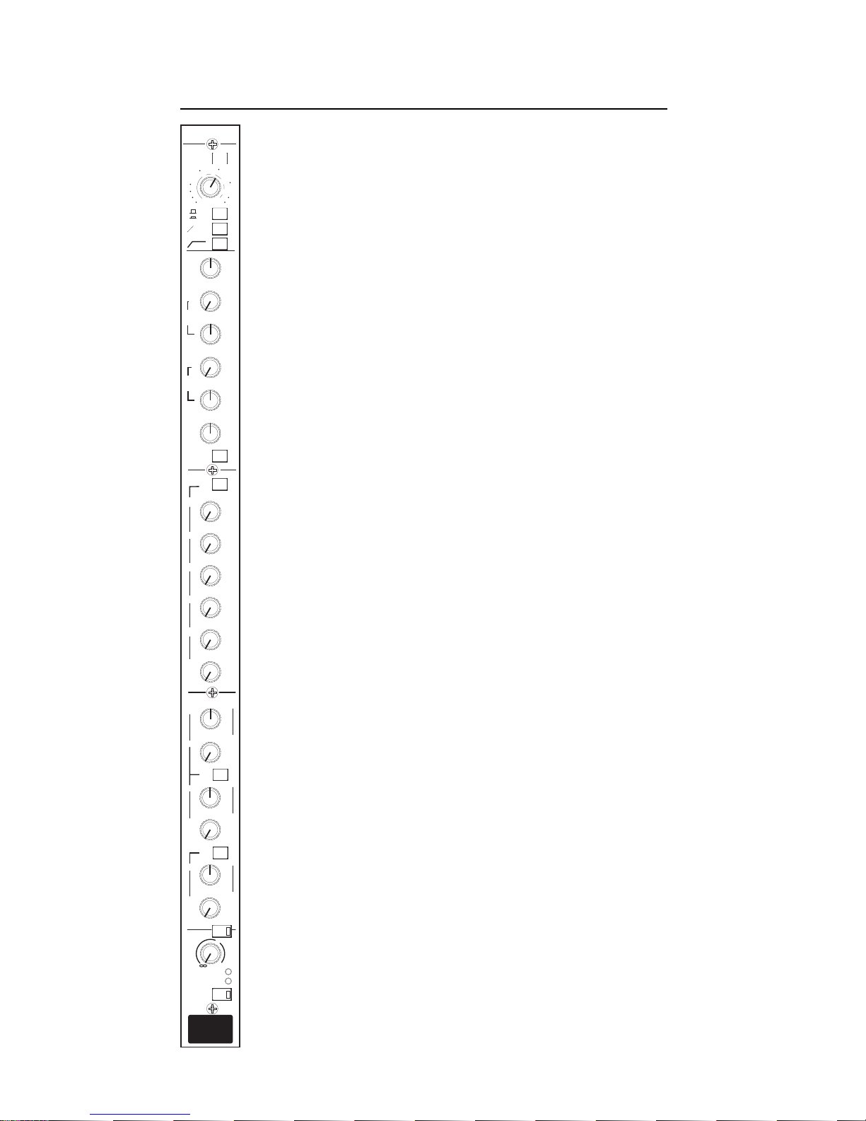
THEMONO INPUTMODULE
Themono inputmodule containsa highquality balancedinput stage
thatisusedfor themicrophoneandline inputsignals.
ThisstageisfollowedbyaHigh PassFilter,EqualiserandInsertPoint
beforethesignalispassedthroughthechannelfadertobecomeavailable
forthemonitorsend buses.Thepreequaliserandtheprefadersignals
can also be used to feed the monitor sends depending upon the
operationalcircumstances.
Atotalof12MonitorSendsare available,6of whichcanbe switched
forstereooperation,thetwolevelcontrolsformingaPANandLEVEL
pair.
PEAK and SIGNAL PRESENT leds assist in setting the pre-fade
signallevel and the signalmay be metered andlistened to using the
PFLfacility.
LF
LO
MID
HI
MID
SIG
PEAK
LEVEL
+
10
0
LEVEL
PAN
12
11
PRE
LEVEL
10
9PAN
PRE
+48V
-10 20
05
10
15
REV
80Hz
O
15
20
65
30
40
50
LO
HI
LR
LR
LEVEL
LR
8
7PAN
6
5
4
3
0
1
2
3
45
10
8
6
7
9
0
1
2
3
45
10
8
6
7
9
0
1
2
3
45
10
8
6
7
9
0
1
2
3
45
10
8
6
7
9
0
1
2
3
45
10
8
6
7
9
0
1
2
3
45
10
8
6
7
9
0
1
2
3
45
10
8
6
7
9
0
1
2
3
45
10
8
6
7
9
0
1
2
3
45
10
8
6
7
9
0
1
2
3
45
10
8
6
7
9
0
1
2
3
45
10
8
6
7
9
0
1
2
3
45
10
8
6
7
9
2
1
0
33
66
99
12 12
15 15
+
-
0
33
66
99
12 12
15 15
+
-
0
33
66
99
12 12
15 15
+
-
HF
0
33
66
99
12 12
15 15
+
-
1K8 3K5
800 7K5
15K470
70
100
250 500
1K2
2K2
PRE
MUTE
PFL
100Hz
10kHz
EQ
GAIN

13
THE MONO INPUT MODULE
+48V
Provides 48 volt phantom power for a condenser
microphone,orD.I.box. The48VON switchonthemaster
modulemustbeONforphantompowertooperate.Optional
balancingtransformersmaybefittedtotheMic/LineInputs.
GAINPOTENTIOMETER
Thegaincontrolisa widerangerotarypotentiometerwhich
isactiveonbothMicandLineInputs. WithHigain selected
the gain can be adjusted from 15dB to 65dB. For Lo gain
inputs,the adjustmentis from -10dBto +20dB.
HI/LOGAIN
Pressingthisinserts anattenuator intothe inputcircuit andaltersthe rangeof gain
adjustmentavailable.Thisshouldbepressedwhenhighlevelorlinelevelsignalsare
connected to the channel through the line input jack. Note that if a jack is not
insertedinto theline inputsocket thenthe XLRconnector maybe usedas theline
input.The TRSjack couldalso beused asa microphoneinput althoughthis isnot
recommendedandphantom powerwillnot beavailable.
Ø REV
Pressingthisreverses thephase(ormorecorrectlythepolarity) oftheinput signal.
Ifa sound source ispicked up by morethan one microphone andthereis a phase
orpolaritydifferencebetween themicrophonesthenthe signalmaybecompletely
orpartiallycancelledleadingto averythinsound.Phase orpolarityreversalcanbe
usedto correctthe situation. Insome instances thecancellation induced byusing
polarityreversalcanbeusedconstructivelytoeliminate spillfromonemicrophone
toanotheralthoughcare isrequiredwhen tryingthis.
80Hz
Thisinsertsan80Hzhighpassfilterwith arolloffof18dBperoctave intothesignal
pathaftertheinputamplifier.Thismaybeusedtoeliminateunwantedlow-frequency
noisestransmittedtothemicrophonethrougha floorstandforexample.
MONO INPUT MODULE

14 CS12M OPERATION MANUAL
THEEQUALISER
Theequaliserisa 4banddesign withshelvinghighandlow
sectionsin addition to two swept mid frequency sections.
Allsections havea range of+/-15dB.
HF
Ashelvinghighfrequencyequaliseroperatingat10kHzwhich
canbeusedtoboostorcutthehigh frequencycontentofthe
signal.
HIMID
Apeakingequaliserwhichcanbeusedtoboost orcutsignal
withinthefrequencyrange 470Hzto15kHzwith aQof1.4.
LO MID
Apeakingequaliserwhichcanbeusedtoboost orcutsignal
withinthefrequency range70Hzto 2.2kHzwitha Qof1.4.
LF
Ashelvinglowfrequencyequaliseroperatingat100Hzwhich
canbeused toboost orcutthe lowfrequency contentof the
signal.
EQ
Thisswitchinsertsthe equaliserintothe signalpath.Ifthe equaliserisnotrequired
thennoiseanddistortion,althoughvery low,canbeminimisedbyensuringthatthe
equaliser is not switched into circuit. If the equaliser is used then an immediate
comparison between the unequalised and equalised sound is made possible by
usingthisswitch.
INSERT
Althoughthereisno frontpanelcontroltheinsertpointfollows theequaliser.With
nothingpluggedinto theinsertjacksignalis simplypassedthrough tothe channel
fader. Whenajackisinserted thesignal pathisbroken andsignal isforcedtoflow
throughanexternaldevicebeforereturningtothemodule.Theinsertreturnsignalis
used to operate the PEAK and SIG leds.
LF
LO
MID
HI
MID
0
33
66
99
12 12
15 15
+
-
0
33
66
99
12 12
15 15
+
-
0
33
66
99
12 12
15 15
+
-
HF
0
33
66
99
12 12
15 15
+
-
1K8 3K5
800 7K5
15K470
70
100
250 500
1K2
2K2
100Hz
10kHz
EQ

15MONO INPUT MODULE
EQUALISATIONAND FILTER RESPONSES
HIGHPASS FILTER
HIMID EQUALISER
LOMID EQUALISER
HF/LFEQUALISER

16 CS12M OPERATION MANUAL
THE MONITOR SENDS 1—12
There are 12 monitor sends six of which can be used as
stereo pairs or individual mono sends. All sends are post
fade until a PRE switch is pressed. There are three PRE
switchescovering sends1-6, 7-10 andfinally 11-12.
MONITOR SENDS 1/2/3/4/5/6/7/8/9/10/11/12
Thesecontrolsadjustthesignalleveltotheindividualmonitor
sends.Thus tosend moresignal toMonitor Send 2simply
turnupthecontrol. Notethatthese monitorsendsnormally
receive the POST FADE signal and that the PRE switch
mustbe pressed to obtaina pre fade signal.
Monitorsends 7through 12can beusedasstereosendsby
pressingthe STEREOswitch onthe output moduleand in
thiscasethe oddnumberedcontrol,for examplenumber7,
willbeusedtopanthemonosignalacrossthe stereooutput.
Theevennumberedcontrol, forexamplenumber8, willbe
usedas thelevel control.
PRE 1-6
This sends a prefade signal to Monitors 1 through 6.
Normallyinternal link7 willbeinstalled givinga prefade
postmutesignal.Removinglink7andinsertinglink8allows
apre equalisersignal to besent.
PRE 7-10
This sends a prefade signal to Monitors 7 through 10.
Normallyinternal link3 willbeinstalled givinga prefade
postmutesignal.Removinglink3andinsertinglink4allows
apre equalisersignal to besent.
PRE 11-12
ThissendsaprefadesignaltoMonitors11and12.Normally
internallink 5will beinstalled giving apre fadepost mute
signal. Removing link 5 and inserting link 6 allows a pre
equalisersignalto besent.
LEVEL
PAN
12
11
PRE
LEVEL
10
9
PAN
PRE
LR
LR
LEVEL
LR
8
7
PAN
6
5
4
3
0
1
2
3
45
10
8
6
7
9
0
1
2
3
45
10
8
6
7
9
0
1
2
3
45
10
8
6
7
9
0
1
2
3
45
10
8
6
7
9
0
1
2
3
45
10
8
6
7
9
0
1
2
3
45
10
8
6
7
9
0
1
2
3
45
10
8
6
7
9
0
1
2
3
45
10
8
6
7
9
0
1
2
3
45
10
8
6
7
9
0
1
2
3
45
10
8
6
7
9
0
1
2
3
45
10
8
6
7
9
0
1
2
3
45
10
8
6
7
9
2
1
PRE

17
THECHANNEL FADER
MUTE
Whenpressed this mutes the POST FADEsignal andany
POSTFADEmonitor sends.
LEVEL
Thisrotary controladjusts thepost fadesignal levelwithin
themodule.Anymonitorsendreceivingthepostfadesignal
willbedependent uponthis fader.
PEAK
Thisilluminateswhenthesignallevelistoohighandcloseto
beingclipped.Clipping is a severe form of distortion and
indicatesthattheinputgainofthemoduleshouldbereduced.
SIG
Thisilluminatesin thepresenceof signaland maybea usefuldiagnosticaidinthe
eventofany problems.
PFL
Thisallowsthemodulesignaltobelistenedtoinisolationonthemonitoringsystem.
Ifpressed whenan outputAFL isactive theoutputwill bemuted sothat theinput
canbe heard. When theinputPFL is released theoutput AFL will be returnedto
thelocalmonitor. Thisisknownas inputpriority.
MONO INPUT MODULE

18 CS12M OPERATION MANUAL
MONO INPUT CONNECTOR AND PIN DEFINITIONS
MicLine Input:3 PinFemale XLRtype,
BalancedPin2 “Hot”
NominalInputLevel: -16dButo -66dBu
Pin2: Signal+ve (Hot)
Pin3 :Signal -ve(Cold)
Pin1: Ground
Input Impedance : >2 kOhm
SplitOutput :3 PinMale XLR type,
BalancedPin2 “Hot”
NominalOutput Level:-16dBu to-66dBu
Pin2: Signal+ve (Hot)
Pin3 :Signal -ve(Cold)
Pin1: Ground
LineInput : 1/4"TRS Jack Socket,‘A’Gauge, Balanced
NominalInputLevel: -16dButo +14dBu
Tip: Signal +ve (Hot)
Ring: Signal-ve (Cold)
Sleeve:Ground
InputImpedance : >10kOhm
InsertPoint: 1/4" TRS JackSocket, ‘A’ Gauge, Unbalanced
NominalInput/Outputlevel: 0dBu
Tip: Insert Send
Ring: InsertReturn
Sleeve: Ground
OutputImpedance: <75Ohm
InputImpedance : >10kOhm
The GROUND LIFT switch isolates both the Microphone Input and the Split
connectorfrom the console ground. It may be of usewhen the split connector is
feedingafrontofhouseconsole whenthereisagreatdanger ofgroundloopsbeing
formed.
12
31
23
INPUT XLR
OUTPUT XLR
SIGNAL + (HOT)
SIGNAL - (COLD)
GROUND
PUSH
INSERT
SEND
RETURN
GROUND
LINE INPUT
SIGNAL + (HOT)
SIGNAL - (COLD)
GROUND
12
3
1
23
PUSH
MIC INPUT SPLIT OUTPUT
GROUND
LIFT SWITCH

19
RANGE
4 BAND EQUALISER
EQ
HPF
POST
PRE 1
PRE 2
GAIN
LEVEL PAN
INPUT MODULE
1
2
3
4
5
6
PRE
PRE 1
PRE 2
POST
PEAK
SIGNAL PRESENT
BUS 1 (IDENTICAL TO 2 THROUGH 12)
BUS 7 (IDENTICAL TO BUS 1)
BUS 7L (SIMILAR TO 9L AND 11L)
BUS 8 (SIMILAR TO BUS 1)
BUS 8R (SIMILAR TO BUS 10R AND 12R
LCUE
RCUE
TALKBACK
7
8
20dB to 70dB
-10dB to 20dB
PRE 1
LEVEL PAN
PRE 2
POST
11
12
LEVEL PAN
9
10
48V
9
9L
10
10R
11
11L
12
12R
INPUT (LINE)
INSERT POINT
SPLIT
PHASE
MUTE
PFL
freq.
+/-
15dB
+10dB
INPUT TX OPTION
PFL
LIFT
Ø
PRE
PRE
GROUND
HFLF HI
MID
LO
MID
CHANNEL FADER
MONO INPUT MODULE BLOCK DIAGRAM
MONO INPUT MODULE

20 CS12M OPERATION MANUAL
THESTEREO INPUTMODULE
Thestereo inputmodule containsa highquality balancedinput stage
thatisusedfor themicrophoneandline inputsignals.
Thisstageisfollowedbya HighPassFilter,EqualiserandInsertPoint
beforethesignalispassedthroughthechannelfadertobecomeavailable
forthemonitorsend buses.Thepreequaliser andtheprefader signals
can also be used to feed the monitor sends depending upon the
operationalcircumstances.
Atotalof 12MonitorSends areavailable,6ofwhichcanbe switched
forstereooperation,thetwolevelcontrolsformingaPANandLEVEL
pair.
PEAK and SIGNAL PRESENT leds assist in setting the pre-fade
signallevel and the signalmaybe metered and listenedto using the
PFLfacility.
Thestereo input moduleallows stereo mic orline level signals tobe
fedfrom,forExample:
Keyboards.
StereoOverhead drummicrophones.
Stereosnaredrum microphones.
Audienceambientmicrophonesfor in-hearuse.
Effectreturns.
LF
LO
MID
HI
MID
SIG
PEAK
LEVEL
+
10
0
LEVEL
PAN
12
11
PRE
LEVEL
10
9
PAN
PRE
+48V
-10 20
05
10
15
REV
80Hz
O
15
20
65
30
40
50
LO
HI
LR
LR
LEVEL
LR
8
7
PAN
6
5
4
3
0
1
2
3
45
10
8
6
7
9
0
1
2
3
45
10
8
6
7
9
0
1
2
3
45
10
8
6
7
9
0
1
2
3
45
10
8
6
7
9
0
1
2
3
45
10
8
6
7
9
0
1
2
3
45
10
8
6
7
9
0
1
2
3
45
10
8
6
7
9
0
1
2
3
45
10
8
6
7
9
0
1
2
3
45
10
8
6
7
9
0
1
2
3
45
10
8
6
7
9
0
1
2
3
45
10
8
6
7
9
0
1
2
3
45
10
8
6
7
9
2
1
0
33
66
99
12 12
15 15 +
-
0
33
66
99
12 12
15 15 +
-
0
33
66
99
12 12
15 15 +
-
HF
0
33
66
99
12 12
15 15 +
-
1k5 3K
1k2 6k
14K900
70
100
250 500
1K2
2K2
PRE
MUTE
PFL
100Hz
10kHz
EQ
GAIN
L
STEREO
Table of contents


