Evo Trim Kit for Evo Affinity 25G User manual

R
ASSEMBLY & INSTALLATION MANUAL
Trim Kit for Evo Affinity 25G
Evo, Inc., 20560 SW 115th Ave., Tualatin, OR 97062 USA
Trim Kit for Evo Anity 25G
( Shown installed to granite topped cabinet )
WEIGHT:
SHEET 6 OF 6
SCALE:1:8
DWG NO.
TITLE:
REVISION
DO NOT SCALE DRAWING
MATERIAL:
DATE
NAME
DEBUR AND
BREAK SHARP
EDGES
FINISH:
Q.A
MFG
APPV'D
CHK'D
DRAWN
Evo Incorporated
Beaverton, Oregon 97008
P-503.626.1802 F-503.213.5869
THE INFORMATION CONTAINED IN THIS
DRAWING IS THE SOLE PROPERTY OF
EVO INC.
ANY REPRODUCTION IN PART OR AS A
WHOLE WITHOUT THE WRITTEN PERMISSION
OF EVO INC. IS PROHIBITED.
PROPRIETARY AND CONFIDENTIAL
Sheet Size:A2
UNLESS OTHERWISE SPECIFIED:
DIMENSIONS ARE IN INCHES
TOLERANCES:
LINEAR: .x
.02
.xx
.01
.xxx
.005
ANGULAR:
.5
NOTES:
Copyright © 2020Revision 4-2-2020

ASSEMBLY & INSTALLATION INSTRUCTIONS
Trim Kit for Evo Affinity 25G
Evo, Inc., 20560 SW 115th Ave., Tualatin, OR 97062 USA
22
THIS MANUAL MUST BE RETAINED FOR FUTURE REFERENCE. READ, UNDERSTAND,
AND FOLLOW THE INSTRUCTIONS AND WARNINGS CONTAINED IN THIS MANUAL.
CAUTION POTENTIALLY SHARP METAL EDGES, IF NOT AVOIDED, MAY
RESULT IN MINOR OR MODERATE INJURY.
Notes
Complete Now For Future Reference
Date Purchased ________________________ Location Purchased _______________________
Date Installed __________________________ Location Installed _________________________
To Installer or Person Unpacking Trim Kit
Leave these instructions with purchaser.
To Purchaser:
Keep these instructions for future reference.

ASSEMBLY & INSTALLATION INSTRUCTIONS
Trim Kit for Evo Affinity 25G
Evo, Inc., 20560 SW 115th Ave., Tualatin, OR 97062 USA
3
INSTALLATION CHECKLIST
TRIM KIT COMPONENTS 4
TRIM KIT DIMENSIONS 5 - 6
TRIM KIT ASSEMBLY & INSTALLATION 7 - 11
PAGE #

ASSEMBLY & INSTALLATION INSTRUCTIONS
Trim Kit for Evo Affinity 25G
Evo, Inc., 20560 SW 115th Ave., Tualatin, OR 97062 USA
4
TRIM KIT COMPONENTS
The Trim Kit for the Evo Anity 25G is shipped partially assembled and requires installation and nal
assembly. Included in the kit are six (6) separate stainless steel metal components and one (1) package of
hardware as listed below:
Parts List INCLUDED with Trim Kit
Qty Trim Kit Metal Parts
1 Top Pan
2 Support Beam
2 End Cap (1 Left, 1 Right)
1 Center Panel
11 Universal Mounting Brackets (pre-installed)
Qty Hardware Bag
For Trim Kit Assembly:
8 1/4” - 20 x 1/2” SS Screw
8 1/4” - 20 Nyloc Nut
For Use When Installing Evo Cooktop:
4 1/4” - 20 SS Hex Bolt
4 1/4” SS Lock Washer
Qty Literature Bag
1 Installation Instructions
Items REQUIRED for Assembly
Qty Tools Needed
1 #2 Phillips Screw Driver
1 7/16” Open-End Box Wrench
1 3/8” Open-End Box Wrench
1 Construction Level
Suitable Silicone Sealant
Qty Hardware Needed (Not Included)
26 Suitable construction screws
Top Pan
End Cap x2
Support Beam x2
Center Panel
Universal Mounting Bracket x11
Left End Cap
Right End Cap

ASSEMBLY & INSTALLATION INSTRUCTIONS
Trim Kit for Evo Affinity 25G
Evo, Inc., 20560 SW 115th Ave., Tualatin, OR 97062 USA
R15
7
8
"
11 3
4
"
1 3
4
"
23 7
8
"
1 3
4
"
1
16
"
1
16
"
1
16
"
34 1
2
"
Recommended opening
29"
Recommended opening
1 7
16
"
1 7
16
"
LINE OF SYMETRY
10 5
8
"
34 3
8
"
10 9
16
"
24"
3"
28 15
16
"
27 5
16
"
9 1
8
"
1 1
2
"
3.00
R15
7
8
"
11 3
4
"
1 3
4
"
23 7
8
"
1 3
4
"
1
16
"
1
16
"
1
16
"
34 1
2
"
Recommended opening
29"
Recommended opening
1 7
16
"
1 7
16
"
LINE OF SYMETRY
10 5
8
"
34 3
8
"
10 9
16
"
24"
3"
28 15
16
"
27 5
16
"
9 1
8
"
1 1
2
"
3.00
R15
7
8
"
11 3
4
"
1 3
4
"
23 7
8
"
1 3
4
"
1
16
"
1
16
"
1
16
"
34 1
2
"
Recommended opening
29"
Recommended opening
1 7
16
"
1 7
16
"
LINE OF SYMETRY
10 5
8
"
34 3
8
"
10
9
16
"
24"
3"
28 15
16
"
27 5
16
"
9 1
8
"
1 1
2
"
3.00
Line of Symetry
TOP VIEWFRONT VIEWSIDE VIEW

ASSEMBLY & INSTALLATION INSTRUCTIONS
Trim Kit for Evo Affinity 25G
Evo, Inc., 20560 SW 115th Ave., Tualatin, OR 97062 USA
6
TRIM KIT DIMENSIONS
25.32
.11
Shim Gap
10.68
.11
Bend Radius
A
33.00
.11
Bend Radius
40.00
1.00
27.44
1.00
36.11
30
1.18
34.82
1.46
1.35
25.43
28.43
36.00
DETAIL A
SCALE 1 : 4
25.32
.11
Shim Gap
10.68
.11
Bend Radius
A
33.00
.11
Bend Radius
40.00
1.00
27.44
1.00
36.11
30
1.18
34.82
1.46
1.35
25.43
28.43
36.00
DETAIL A
SCALE 1 : 4
25.32
.11
Shim Gap
10.68
.11
Bend Radius
A
33.00
.11
Bend Radius
40.00
1.00
27.44
1.00
36.11
30
1.18
34.82
1.46
1.35
25.43
28.43
36.00
DETAIL A
SCALE 1 : 4
FRONT VIEW DIMENSIONSTOP VIEW DIMENSIONS
SIDE VIEW DIMENSIONS
25.32
.11
Shim Gap
10.68
.11
Bend Radius
A
33.00
.11
Bend Radius
40.00
1.00
27.44
1.00
36.11
30
1.18
34.82
1.46
1.35
25.43
28.43
36.00
DETAIL A
SCALE 1 : 4
10.68
26.32
34.5
29.0
23.875
1.75
1.5
26.43

ASSEMBLY & INSTALLATION INSTRUCTIONS
Trim Kit for Evo Affinity 25G
Evo, Inc., 20560 SW 115th Ave., Tualatin, OR 97062 USA
STEP 1: Prepare cabinet construction using either wood or steel framing. It is
recommended to have a cutout measuring 29 1/8” depth by 34 1/5” width by 10 5/8”
height.
WEIGHT:
SHEET 4 OF 6
SCALE:1:8
DWG NO.
TITLE:
REVISION
DO NOT SCALE DRAWING
MATERIAL:
DATE
NAME
DEBUR AND
BREAK SHARP
EDGES
FINISH:
Q.A
MFG
APPV'D
CHK'D
DRAWN
Evo Incorporated
Beaverton, Oregon 97008
P-503.626.1802 F-503.213.5869
THE INFORMATION CONTAINED IN THIS
DRAWING IS THE SOLE PROPERTY OF
EVO INC.
ANY REPRODUCTION IN PART OR AS A
WHOLE WITHOUT THE WRITTEN PERMISSION
OF EVO INC. IS PROHIBITED.
PROPRIETARY AND CONFIDENTIAL
Sheet Size:A2
UNLESS OTHERWISE SPECIFIED:
DIMENSIONS ARE IN INCHES
TOLERANCES:
LINEAR: .x
.02
.xx
.01
.xxx
.005
ANGULAR:
.5
NOTES:
34.5” Recommended Opening
29 1/8” Recommended Depth
(Opening)
10 5/8”
Recommended
Height
Back Wall Brace
TRIM KIT ASSEMBLY & INSTALLATION
Recommended Dimensions:

ASSEMBLY & INSTALLATION INSTRUCTIONS
Trim Kit for Evo Affinity 25G
Evo, Inc., 20560 SW 115th Ave., Tualatin, OR 97062 USA
8
Top Pan (Front Edge)
Center Panel (Front Edge)
End Cap
Support Beam (Outside Edge)
Fasten Support Beam and
Center Panel to End Cap using
1/4” - 20 x 1/2” SS Phillips Head
Screw with Nyloc Nut.
STEP 2: Locate Support Beam and Center Panel as shown, and fasten in place with two
(2) 1/4” - 20 x 1/2” SS Phillips Head Screws with Nyloc Nuts.
STEP 3: Repeat same process for opposite side.
TRIM KIT ASSEMBLY & INSTALLATION
Support Beam installs to inside.

ASSEMBLY & INSTALLATION INSTRUCTIONS
Trim Kit for Evo Affinity 25G
Evo, Inc., 20560 SW 115th Ave., Tualatin, OR 97062 USA
WEIGHT:
SHEET 5 OF 6
SCALE:1:8
DWG NO.
TITLE:
REVISION
DO NOT SCALE DRAWING
MATERIAL:
DATE
NAME
DEBUR AND
BREAK SHARP
EDGES
FINISH:
Q.A
MFG
APPV'D
CHK'D
DRAWN
Evo Incorporated
Beaverton, Oregon 97008
P-503.626.1802 F-503.213.5869
THE INFORMATION CONTAINED IN THIS
DRAWING IS THE SOLE PROPERTY OF
EVO INC.
ANY REPRODUCTION IN PART OR AS A
WHOLE WITHOUT THE WRITTEN PERMISSION
OF EVO INC. IS PROHIBITED.
PROPRIETARY AND CONFIDENTIAL
Sheet Size:A2
UNLESS OTHERWISE SPECIFIED:
DIMENSIONS ARE IN INCHES
TOLERANCES:
LINEAR: .x
.02
.xx
.01
.xxx
.005
ANGULAR:
.5
NOTES:
TRIM KIT ASSEMBLY & INSTALLATION
STEP 3: Check dimensions of frame construction t by placing assembled Trim Kit base into
prepared cabinet. Mark location for Back Wall Brace. Align Support Beam to marked position
of Back Wall Brace and check to ensure Support Beam is level and the Front Panel is
positioned to be ush with the front cabinet construction. Attach Support Beam to Back Wall
Brace using suitable construction screws (not included).
Support Beam
Back Wall Brace

ASSEMBLY & INSTALLATION INSTRUCTIONS
Trim Kit for Evo Affinity 25G
Evo, Inc., 20560 SW 115th Ave., Tualatin, OR 97062 USA
10
TRIM KIT ASSEMBLY & INSTALLATION
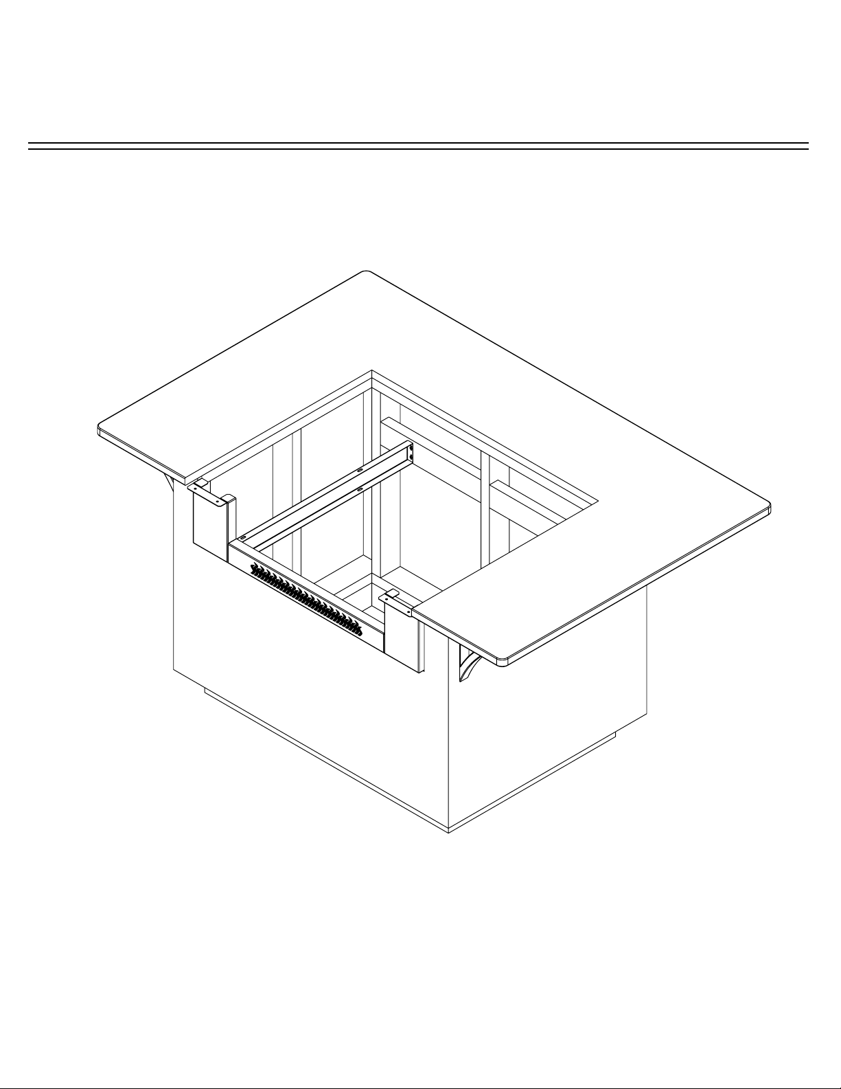
STEP 4: With 3/8” wrench, loosen and turn the eleven (11) installed Universal Mounting
Brackets on Top Pan to a vertical position. Loosely attach rear of Trim Kit Top to cabinet with
two (2) Universal Mounting Brackets and two (2) screws (not included) to hold up and check
for t.
Fasten Top Pan to End Cap
using 1/4” - 20 x 1/2” SS
Phillips Head Screw with Nyloc
Nut.
Turn all eleven (11) Universal Mounting
Brackets to vertical position.
STEP 5: Fasten Top Pan to End Cap using four (4) 1/4”- 20 x 1/2” SS Phillips Head
Screw and Nyloc Nuts as shown. Next shim, level and readjust until Top Pan is ush with
countertop. Secure Top Pan with the remaining nine (9) Universal Mounting Brackets and
nine (9) additional suitable construction screws (not included). It may be necessary to adjust
the location of the Universal Mounting Bracket with a 3/8” open end wrench to align with
cabinet frame. For more stability, secure Trim Kit with up to eleven (11) more screws (not
included) in provided holes as shown.
B
B
C
C
DD
SECTION
B-B
SECTION
C-C
SECTION
D-D
WEIGHT:
SHEET 2 OF 6
SCALE:1:8
DWG NO.
TITLE:
REVISION
DO NOT SCALE DRAWING
MATERIAL:
DATE
NAME
DEBUR AND
BREAK SHARP
EDGES
FINISH:
Q.A
MFG
APPV'D
CHK'D
DRAWN
Evo Incorporated
Beaverton, Oregon 97008
P-503.626.1802 F-503.213.5869
THE INFORMATION CONTAINED IN THIS
DRAWING IS THE SOLE PROPERTY OF
EVO INC.
ANY REPRODUCTION IN PART OR AS A
WHOLE WITHOUT THE WRITTEN PERMISSION
OF EVO INC. IS PROHIBITED.
PROPRIETARY AND CONFIDENTIAL
Sheet Size:A2
UNLESS OTHERWISE SPECIFIED:
DIMENSIONS ARE IN INCHES
TOLERANCES:
LINEAR: .x
.02
.xx
.01
.xxx
.005
ANGULAR:
.5
NOTES:
It is recommended the Trim Kit Top
Pan be level and ush to the adjoining
countertop surface.
For more stability add up to
eleven (11) screws in provided
holes.

ASSEMBLY & INSTALLATION INSTRUCTIONS
Trim Kit for Evo Affinity 25G
Evo, Inc., 20560 SW 115th Ave., Tualatin, OR 97062 USA
TRIM KIT ASSEMBLY & INSTALLATION
STEP 6: Remove two (2) mounting brackets with 7/16” Open End Box Wrench installed on
Evo Anity 25G Cooktop.
STEP 7: To install the Evo cooktop into the assembled and installed Trim Kit, follow the
installation instructions in the Anity 25G Owner’s Manual. It is recommend to seal the gap
between Trim Kit and countertop with silicone (not included).
Mounting Brackets
Ignition system is exposed during uncrating and installation. Use
caution to avoid damage.
Seal gap with
silicone.
Other manuals for Trim Kit for Evo Affinity 25G
1
Table of contents