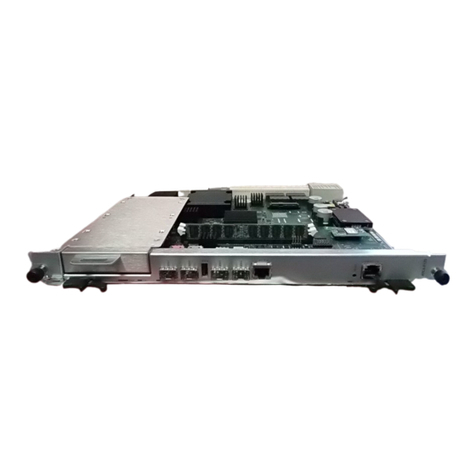
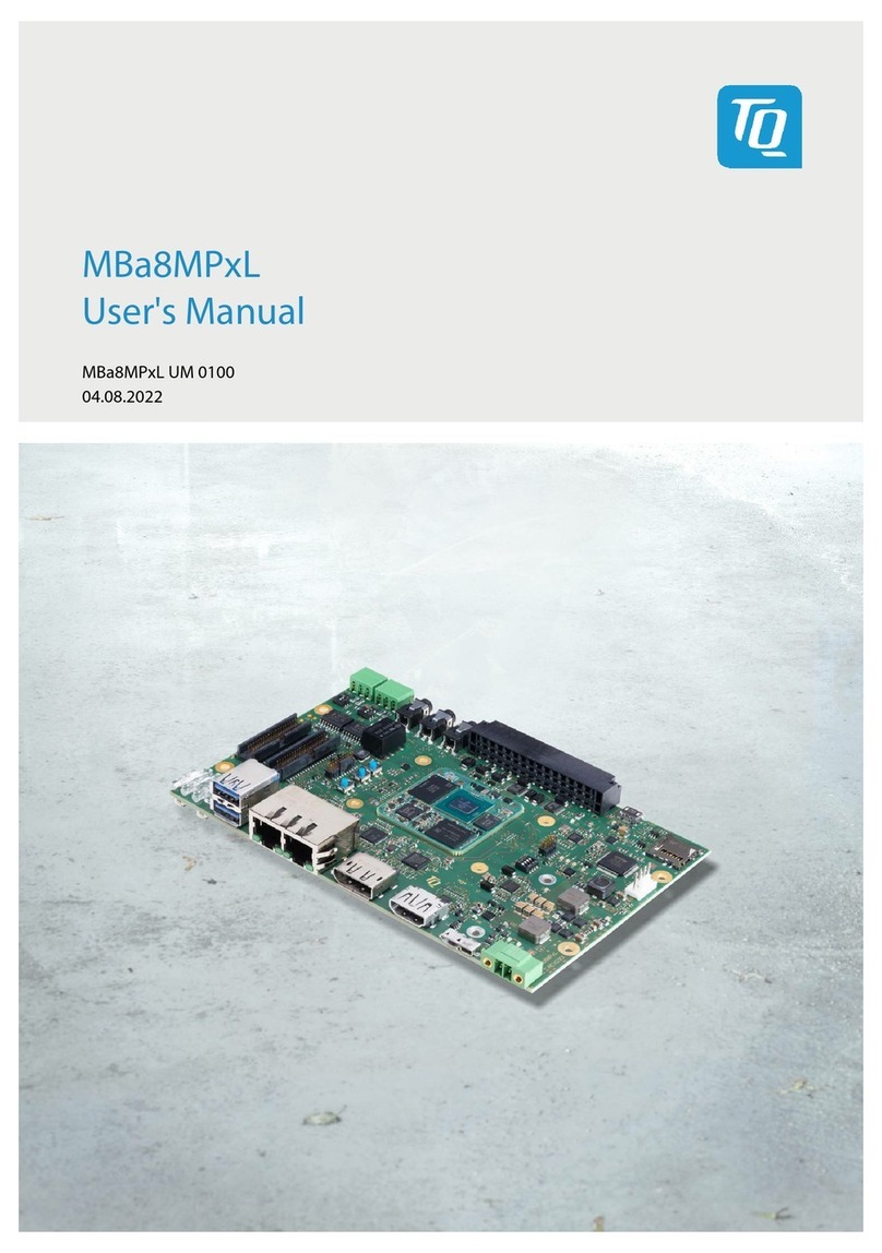
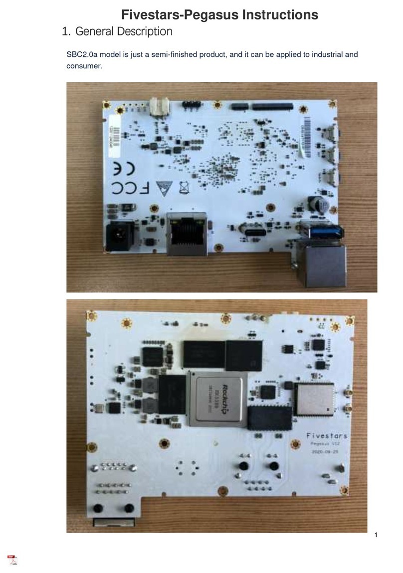
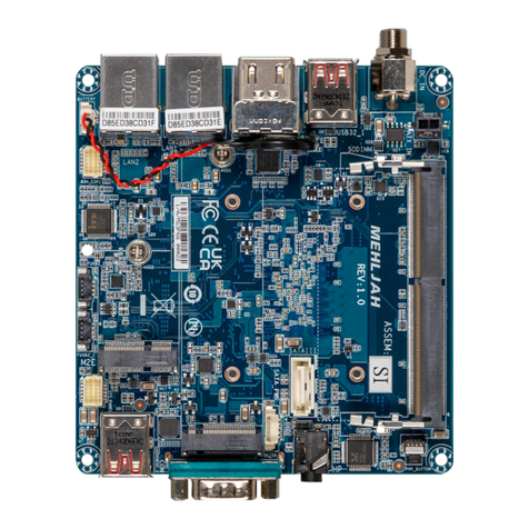
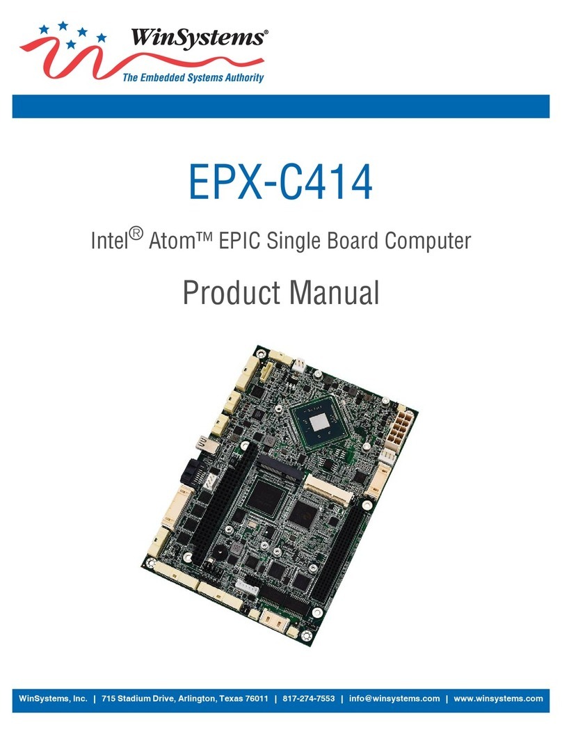
EVOC CPC-3811CLD4N User manual

CPC3811CLD4N
3UCompactPCIMotherboardwithWide
Temperature andLowConsumption
Version:C00

Announcement
What contained inthis User Manual does not represent the commitments of EVOC
Company. EVOC Company reserves the right to revise this User Manual, without
priornotice,andwillnotbeheldliableforanydirect,indirect,intendedorunintended
lossesand/orhiddendangersduetoinstallationorimproperoperation.
Before purchasing, pleasehave a detailedunderstanding of the product performance
toseewhetheritmeetsyourrequirements.
EVOC is a registered trademark of EVOC Intelligent Technology Co., Ltd. All
trademarks, registered trademarks, and trade names used in this User Guide are the
propertyoftheirrespective owners.
EVOCIntelligent TechnologyCo.,Ltd.©2008,CopyrightReserved.Nopartofthis
manual can be reproduced in any form or by any means, such as in electronic or
mechanicalway,withoutpermissioninwritingfromEVOC.
SafetyInstructions
1. Pleasecarefullyreadtheusers’manualbeforehandlingtheproduct;
2. For the board which is not ready to be installed, please put it intheantistatic
packaging;
3. Beforetakingtheboardoutfromantistaticpackaging,please putyourhandon
groundedmetalobjectforawhile(about10seconds)todischargestatic;
4. Pleasewearstaticprotectivegloveswhenholdingtheboard;andalwaysholdthe
boardbyedges;
5. Before inserting, removing or reconfiguring the motherboard or the expansion
card,pleasefirstlydisconnecttheACpowerorunplugtheACpowercablefrom
the power source to prevent damage to the product and ensure your personal
safety;
6. BeforeremovingtheboardsorPCboxes,firstlyturnoffallpowerresourcesand
unplugthepowercablefrompowersource;
7. ForPCBoxproducts,wheninsertingorremovingboards,pleasedisconnectthe
ACpowerinadvance;
8. Before connecting or disconnecting any device, make sureall power cablesare
unpluggedinadvance;
9. Toavoidunnecessarydamagecausedbyturningon/offcomputerfrequently,wait
atleast30secondsbeforereturningonthecomputer.

Contents
Chapter1ProductIntroduction ................................................................................1
Overview ............................................................................................................1
EnvironmentandDimensions ..............................................................................1
TypicalPowerConsumption ................................................................................2
CPU....................................................................................................................2
Chipset ...............................................................................................................2
SystemMemory..................................................................................................2
VideoFunction....................................................................................................3
LAN ...................................................................................................................3
PowerFeature .....................................................................................................3
ExpansionBus ....................................................................................................3
StorageDevices...................................................................................................3
ExternalI/OInterfaces.........................................................................................4
WatchdogFunction..............................................................................................4
Chapter2Installation...............................................................................................5
ProductOutline ...................................................................................................5
TheLocationsofInterfaces..................................................................................7
InstructionofCPC3811CLD4N1.......................................................................9
JumperSetup ..................................................................................................9
JTAGInterface ...............................................................................................9
ResetSwitch.................................................................................................10
CompactPCIInterface..................................................................................10
ConnecterbetweenBoards ............................................................................12
USBInterface ...............................................................................................13
Indicator .......................................................................................................13
LANPort......................................................................................................13

VideoInterface............................................................................................. 14
InstructionofCPC3811CLD4N2 .................................................................... 15
JumperSetting.................................................................................................. 15
LVDSBacklightControl............................................................................... 15
SerialPort .................................................................................................... 16
KeyboardandMouseInterface...................................................................... 17
USBInterface............................................................................................... 17
LVDSInterface ............................................................................................ 17
SATAInterface............................................................................................. 18
ConnecterbetweenBoards............................................................................ 18
InstructionofIOBoardCPCRP38111............................................................. 19
JumperSetting ............................................................................................. 19
SerialPort .................................................................................................... 19
SATAInterface............................................................................................. 19
ConnecterbetweenBoards............................................................................ 20
LANPort ..................................................................................................... 20
USBInterface............................................................................................... 20
CompactPCIInterface ................................................................................. 20
InstructionofIOBoardCPCRP38112............................................................. 21
ConnecterbetweenBoards............................................................................ 21
OpticalLANPortIndicator........................................................................... 21
OpticalLANPort ......................................................................................... 21
Chapter3BIOSSetup ........................................................................................... 22
Appendix.............................................................................................................. 23
WatchdogProgrammingGuide.......................................................................... 23
I/OAddressMap............................................................................................... 25
IRQAssignmentTable ...................................................................................... 26

Chapter1ProductIntroduction
CPC3811CLD4N -1-
Chapter1ProductIntroduction
Overview
CPC3811CLD4N CPCI single board computer is committed to provide a system
managementplatformblending highperformancecalculation,managementplatform,
advanced network transmitting platform and highperformance storage platform
together. It is also committed to meet the requirement of radar image processing
customersfora3UCPCI withdualcore,multinetworkportandindependentdisplay
card.
CPC3811CLD4N CPCI adopts Intel 45nm Intel® Core 2 Duo Processors, withits
codename as Penryn. L2 cache reaches up to 3M, which supports New SSE4
command. It adopts Intel® 3100 Chipset with Codename as Whitmore Lake and
support 800 FSB. Onboard DDR2 ECC REG memory supports up to 1GB and
integrates abundant external interfaces; it features in high performance and low
consumption,whichisquitesuitableforanembeddedplatform.We’vedesigneda3U
CompactPCI system board with dualcore based on the platform, which supports
complete hotswap; four 10/100/1000Mbps Ethernet ports; two SFP optical socket
ports; it adopts PCIindependentdisplaycard connectedby PCI,32bit memory bus
and independent display memory up to 32MB; it also supports VGA+LVDS
independent dualdisplay.
EnvironmentandDimensions
l OperatingEnvironment:
Temperature: 20 °C~70°C
Humidity:5%~95%(Noncondensing);

Chapter1ProductIntroduction
-2-CPC3811CLD4N
l StorageTemperature:
Temperature: 40°C~85°C;
Humidity:5%~95%(Noncondensing);
l Dimension:
CPC3811CLD4N1:161.50mm×100.00mm;
CPC3811CLD4N2:46.38mm×100.00mm;
CPCRP38111:81.50mm×100.00mm;
CPCRP38112:66.00mm×100.00mm.
TypicalPowerConsumption
CPU: onboardIntelCore2DuoU93001.20GHz
Memory: onboard SamsungDDRII4001G
l +5V@4.9A; +5%/3%;
l +3.3V@4.23A; +5%/3%;
l +12V@0.79A; +5%/3%;
CPU
Intel Core 2 Duo CPU SU9300, 800MHz FSB,1.2GHzprimary frequency, 3M L2
cache,uBGASFF (956balls) package.
Chipset
Intel®3100Chipset,800MHzFSB,bothnorthandsouthbridgeintegratesasasingle
chip.
SystemMemory
Onboard 1GB400MHzDDR2 memory.

Chapter1ProductIntroduction
CPC3811CLD4N -3-
VideoFunction
Adopt XGI Z9S PCI independent display chip, 32bit memory bus, 32MB
independentdisplaymemoryandsupportCRT+LVDSindependentdualdisplay.CRT
supportsupto 1600x1200@60Hz.
LAN
ExpandthroughtwoPCIEx1andonePCIEx4channels;connectwithtwoRealtek
8111C and one Intel 82571; four 10/100/1000MbpsEthernet electric portsandtwo
1000Mbps Ethernet optical ports. The two electric ports and two optical ports of
Intel82571 support TRUNK function. The electrical ports and optical ports of
Intel82571are optional.
PowerFeature
The power conversion chips on the single board include MAX8771, ISL6532,
TPS51124 and so on. CPU power is adjusted by 5V through IMVP6+ MAX8771
GTL+chip;itsmaximumcurrentis 18A.
ExpansionBus
Intel®3100PCI32bit/33BusprovidesCompactPCIbus:3U32bitCompactPCIbus
standard,compatiblewithPICMG2.0, PICMG2.1.
StorageDevices
Onboardonepowered 7+15pin SATA interfaceandtwo 7pin SATA interfaces.

Chapter1ProductIntroduction
-4-CPC3811CLD4N
ExternalI/OInterfaces
l Four USB2.0 interfaces;
l TwoCOMswithDB9interfaceandoneCOMpin(among whichCOMswithDB9
interfaces areRS232/RS422/RS485optional; the COM pin only supports RS232
modeanditisoptional withthe DB9interfaceonmotherboard);
l OnePS/2 keyboardandmouseinterface(provideby SMSC3114).
WatchdogFunction
l 1255 secondsor 1255minutes, 510 levels;
l Watchdogovertimeinterruptorresetsystem.

Chapter2Installation
CPC3811CLD4N -5-
Chapter2Installation
ProductOutline
19.93
86.00
161.50
54.07
74.00
88.90
85.00
10.00
100.00
80.00
CPC3811CLD4N1

Chapter2Installation
-6-CPC3811CLD4N
4.00
42.38 46.38
58.16
100.00
CPC3811CLD4N2
100.00
19.93
81.50
88.90
60.07
80.00 10.00
77.00
CPCRP38111
88.90 5.55
100.00
5.93
66.00
CPCRP38112
Unit:mm

Chapter2Installation
CPC3811CLD4N -7-
TheLocationsofInterfaces
D5
SW1
USB1
LAN1
VGA1
CONN1
JCC1
J2 JTAG1 J1 JP1
CPC3811CLD4N1

Chapter2Installation
-8-CPC3811CLD4N
KM1
CONN1
USB1
COM1
JP2
JP3
JP1
SATA1
LVDS1
JLCD1
CPC3811CLD4N2
LAN1
COM1
USB2 USB1
JP1
JP2
CONN1
J1
SATA2
SATA1
CPCRP38111
CONN1
SFP2 SFP1
D2 D1
CPCRP38112

Chapter2Installation
CPC3811CLD4N -9-
Tip: Howtoidentifythefirstpinofthejumpersandinterfaces
1. Observe the letter beside the socket, it would be marked with “1” or thickened
linesortriangularsymbols;
2. Observethesolderpadontheback, thesquarepad isthefirstpin;
3. Theredlineonthecableorothermarks showsthattheyshouldbeconnectedwith
thefirstpin of the socket.
Instructionof CPC3811CLD4N1
JumperSetup
(1) JCC1:Clear/Keep CMOS Setting
CMOSispoweredbytheonboardbuttonbattery.ClearCMOSwillrestoreoriginal
settings (factorydefault).Thestepsarelistedasfollows:
a) Turnoffthecomputerandunplugthepowercable;
b) InstantlyshortJCC1;
c) Turnonthecomputer;
d) EnterBIOSsetupwhenstartingthecomputer, reloadoptimizeddefaults;
e) Saveandexitsetupmode.
JCC1
Setup Function
12Open Normal(Default)
12Short ClearthecontentofCMOS,alltheBIOSsetting
resumetofactorydefaultvalue.
(2) JP1: PowerSwitchSelection
JP1
Setup Function
12Open Poweroff
12Short Poweron
JTAGInterface
JTAG1
Pin SignalName
1 VCC
2 GND
3 TCK
4 TDO
5 TDI
6 TMS

Chapter2Installation
- 10 -CPC3811CLD4N
ResetSwitch
CPC3811CLD4N1providesoneresetbuttonSW1.Pressthebuttonandthesystem
willreset.
CompactPCIInterface
(1) PinDefinitionsof J1
J1
Pin SignalName
A B C D E F
1 +5V 12V TRST# +12V +5V GND
2 TCK +5V TMS# TDO TDI GND
3 INTA# IRQB# INTC# +5V INTD# GND
4 IPMB_PWR HEALTHY# V(I/O) INTP INTS GND
5 NC NC PCI_RST# GND GNT0# GND
6 REQ0# PCI_PRESENT# +3.3V CLK0 AD31 GND
7 AD30 AD29 AD28 GND AD27 GND
8 AD26 GND V(I/O) AD25 AD24 GND
9 C/BE3# GND AD23 GND AD22 GND
10 AD21 GND +3.3V AD20 AD19 GND
11 AD18 AD17 AD16 GND C/BE2# GND
12
KEYAREA13
14
15 +3.3V FRAME# IRDY# BD_SEL# TRDY# GND
16 DEVSEL# GND V(I/O) STOP# LOCK# GND
17 +3.3V IPMB_SCL IPMB_SDA GND PERR# GND
18 SERR# GND +3.3V PAR C/BE1# GND
19 +3.3V AD15 AD14 GND AD13 GND
20 AD12 GND V(I/O) AD11 AD10 GND
21 +3.3V AD9 AD8 M66EN C/BE0# GND
22 AD7 GND +3.3V AD6 AD5 GND

Chapter2Installation
CPC3811CLD4N - 11 -
23 +3.3V AD4 AD3 +5V AD2 GND
24 AD1 +5V V(I/O) AD0 ACK64# GND
25 +5V REQ64# ENUM# +3.3V +5V GND
(2) PinDefinitionofJ2
J2
Pin A B C D E F
22 CPCI_GA4 CPCI_GA3 CPCI_GA2 CPCI_GA1 CPCI_GA0 GND
21 SPCI_CLK6 GND USB_DN3 NC NC GND
20 SPCI_CLK5 GND USB_DP3 GND NC GND
19 GND GND CPCI_SMB
B_SDA
CPCI_SM
BB_SCL
CPCI_SMB
B_ALERT
GND
18 VCC5 VCC5 VCC5 GND COM2_DCD GND
17 NC GND CPCI_PRST PCI_REQ6 PCI_GNT6 GND
16 CLK_PCIE_LAN3+ NC CPCI_DEG GND COM2_RI GND
15 CLK_PCIE_LAN3 GND CPCI_FAL PCI_REQ5 PCI_GNT5 GND
14 PCIE_A_RXN3 PCIE_A_TXN3 PCIE_A_TXP3 GND USB_DN2 GND
13 PCIE_A_RXP3 GND NC COM2_DTR USB_DP2 GND
12 PCIE_A_RXN2 PCIE_A_TXN2 PCIE_A_TXP2 GND USB_OC23 GND
11 PCIE_A_RXP2 GND NC COM2_RTS SATA_TXP1 GND
10 PCIE_A_RXN1 PCIE_A_TXN1 PCIE_A_TXP1 GND SATA_TXN1 GND
9 PCIE_A_RXP1 GND NC COM2_DSR SATA_RXN1 GND
8 PCIE_A_RXN0 PCIE_A_TXN0 PCIE_A_TXP0 GND SATA_RXP1 GND
7 PCIE_A_RXP0 GND NC COM2_CTS SATA_TXP2 GND
6 PLTRST_B SATA_RXN2 SATA_RXP2 GND SATA_TXN2 GND
5 VCC3_3 GND NC COM2_SOUT GND GND
4 NC VCC3_3 COM2_SIN GND VCC5SB GND
3 SPCI_CLK4 GND PCI_GNT3 PCI_REQ4 PCI_GNT4 GND
2 SPCI_CLK2 SPCI_CLK3 SYS_EN PCI_GNT2 PCI_REQ3 GND
1 SPCI_CLK1 GND PCI_REQ1 PCI_GNT1 PCI_REQ2 GND

Chapter2Installation
- 12 -CPC3811CLD4N
ConnecterbetweenBoards
CONN1,itspindefinitionsareasfollows:
Pin SignalName Pin SignalName Pin SignalName
A1 LVDS_D0+ A2 GND A3 LVDS_D1+
A4 GND A5 LVDS_D2+ A6 GND
A7 LVDS_D3+ A8 GND A9 LVDS_CLK+
A10 LVDS_VDDEN A11 USB_DP1 A12 GND
A13 SATA_RXN0 A14 GND A15 SATA_TXN0
A16 GND A17 COM1_CTS A18 COM1_RI
A19 COM1_DCD A20 COM1_SOUT A21 KB_DATA
A22 KB_CLK A23 VCC12 A24 VCC12
A25 VCC5 B1 LVDS_D0 B2 GND
B3 LVDS_D1 B4 GND B5 LVDS_D2
B6 GND B7 LVDS_D3 B8 GND
B9 LVDS_CLK B10 USB_OC1 B11 USB_DN1
B12 GND B13 SATA_RXP0 B14 GND
B15 SATA_TXP0 B16 LVDS_BKLTEN B17 COM1_SIN
B18 COM1_DTR B19 COM1_RTS B20 COM1_DSR
B21 MS_DATA B22 MS_CLK B23 VCC3_3
B24 VCC5 B25 VCC5 G1 GND
G2 GND G3 GND G4 GND
G5 GND G6 GND G7 GND
G8 GND G9 GND G10 GND
G11 GND G12 GND G13 GND
G14 GND G15 GND G16 GND
G17 GND G18 GND

Chapter2Installation
CPC3811CLD4N - 13 -
USBInterface
The board provides with one standard USB socket. The table below shows its pin
definitions.
USB1
Pin SignalName
1 +5V
2 USB_Data
3 USB_Data+
4 GND
Indicator
D5
LED Status Description
Watchdog
(WDT)
OFF Watchdogisnotoperating
ON Watchdogisoperating
Hotswap
(HS)
OFF Normaloperatingstatus
ON Underhotswapping
HardDisk
(HDD)
OFF Harddiskisnotused
ON Harddiskisoperating
Power
(PWR)
OFF Powerfailure
ON PowerisOK
LANPort
CPC3811CLD4N1 provides two 10/100/1000Mbps Ethernet ports; LILED and
ACTLEDaretwostatusindicatorsbesidetheLANport,whichshowtheconnecting
andactivestatusoftheLAN.PleaserefertothefollowingLEDstatus descriptions:

Chapter2Installation
- 14 -CPC3811CLD4N
LAN1
ACTLED
(SingleColor:
Green)
LANActivity
Indicating
LILED
(Dualcolors:
Yellow/Green)
LAN
Speed
Indicating
Green 1000Mbps
Blink DataTransmitting Yellow 100Mbps
OFF Nodataistransmitting Off 10Mbps
VideoInterface
The board providesonestandardDB15VGA interfaceanditspindefinitionsareas
follows:
VGA1
Pin SignalName Pin SignalName
1 Red 2 Green
3 Blue 4 NC
5 GND 6 GND
7 GND 8 GND
9 +5V 10 GND
11 NC 12 DDCDATA
13 HSYNC 14 VSYNC
15 DDCCLK

Chapter2Installation
CPC3811CLD4N - 15 -
Instructionof CPC3811CLD4N2
JumperSetting
(1) JP1: COM RS232/RS422/RS485 ModeSelection
JP1
Mode
Selection
PinSetup
12 34 56
RS232 ON(Default) OFF OFF
RS422 OFF OFF ON
RS485 OFF ON OFF
Note: 1.ON isshortand OFF isopen;
2. Whenusing JP3,JP1 shallbesetto RS232 mode.
(2) JLCD1:LCD OperatingVoltageSelection
Different LCD screens have different voltages. The board provides two kinds of
voltages: 3.3V and 5V. When the selected LCD voltage is conformed to the LCD
screenvoltageinuse,theLCDscreencandisplaynormally.
JLCD1
Setup Function
12Short +3.3V (Default)
23Short +5V
LVDSBacklightControl
JP2
Pin SignalName
1 NC
2 NC
3 LVDS_BKLTEN
4 GND

Chapter2Installation
- 16 -CPC3811CLD4N
SerialPort
The board provides a standard DB9 interface COM1, and one 2x5Pin COM
pin, JP3, among which COM1 could realize RS232/RS422/RS485 mode
selection via JP1. JP3 supports RS232 mode and JP3andCOM1can beselected
alternatively.
COM1
Pin
SignalName
RS232 RS422 RS485
1 DCD# TXD Data
2 RXD TXD+ Data+
3 TXD RXD+ X
4 DTR# RXD X
5 GND GND GND
6 DSR# X X
7 RTS# X X
8 CTS# X X
9 RI# X X
JP3
Pin SignalName
1 DCD#
2 RXD
3 TXD
4 DTR#
5 GND
6 DSR#
7 RTS#
8 CTS#
9 RI#
10 NC
This manual suits for next models
4
Table of contents
Other EVOC Single Board Computer manuals
