Evolution Amps AMBER 40 User manual

-1-
Thank you for choosing Evolution amp. We are proud to provide you with the new unique
technology guitar amp. We are convinced you will be delighted by the classic guitar sounds,
performance and functionality of our product.
Enjoy your playing,
Evolution Amps Team.
PLEASE read this instruction manual carefully before switching on.
This symbol is intended to alert the user to the presence of uninsulated “dangerous
voltage“ within the product‘s enclosure that may be of sufficient magnitude to constitute a
risk of electric shock to persons.
This symbol is intended to alert the user to the presence of important operation and
maintenance (servicing) instructions in the literature accompanying the appliance.
WARNING! - Important safety instructions
CAUTION!
RISK OF ELECTRIC SHOCK.
DO NOT REMOVE SCREWS.
DO NOT OPEN.
To reduce the risk of fire or electric shock do not expose this unit to rain or
moisture and objects filled with liquids‚ such as vases‚ should not be placed on this
apparatus. Do not use this apparatus near water (e. g swimming pool).
WARRNING ! This apparatus shall be connected to a mains socket outlet with a
protective earthing connection. Unplug this apparatus during lightning storms or
when unused for long periods of time.
Protect the power cord from being walked on or pinched particularly at plugs,
convenience receptacles, and the point where they exit from the apparatus.
Do not block any ventilation openings. Clean only with dry cloth.
Do not switch the amplifier on without the loudspeaker connected.
No user serviceable parts inside. Refer servicing to qualified service personnel.
Servicing is required when the unit has been damaged in any way, such as:
- when the power cord or plug is frayed or damaged
- if liquid has been spilled or objects have fallen into the product
- if the product has been exposed to rain or moisture
- if the cabinet has been damaged or the product has been dropped
- if the product does not operate normally when the operating instructions are
followed

-2-
FCC Compliance
This device complies with Part 15 of the FCC Rules. Operation is subject to the following two
conditions: (1) this device may not cause harmful interference, and (2) this device must accept any
interference received, including interference that may cause undesired operation.
NOTE: This equipment has been tested and found to comply with the limits for a Class B digital
device, pursuant to Part 15 of the FCC Rules. These limits are designed to provide reasonable
protection against harmful interference in a residential installation. This equipment generates, uses
and can radiate radio frequency energy and, if not installed and used in accordance with the
instructions, may cause harmful interference to radio communications. However, there is no
guarantee that interference will not occur in a particular installation.
If this equipment does cause harmful interference to radio or television reception, which can be
determined by turning the equipment off and on, the user is encouraged to try to correct the
interference by one or more of the following measures:
–
Reorient or relocate the receiving antenna.
–
Increase the separation between the equipment and receiver.
–
Connect the equipment into an outlet on a circuit different from
that to which the receiver is connected.
–
Consult the dealer for help.
Exposure to extremely high sound levels may cause a permanent hearing loss. The U.S.
Government's Occupational Safety and Health Administration (OSHA) has specified the following
permissible noise level exposures:
Duration Per Day In Hours
Sound Level dBA, Slow Response
8
90
6
92
4
95
3
97
2
100
1.5
102
1
105
0.5
110
0.25 or less
115
According to OSHA, any exposure in excess of the above permissible limits could result in some
hearing loss. Earplugs or protectors in the ear canals or over the ears must be worn when
operating this amplification system in order to prevent a permanent hearing loss if exposure is in
excess of the limits as set forth above. To ensure against potentially dangerous exposure to high
sound pressure levels, it is recommended that persons exposed to equipment capable of
producing high sound pressure levels such as this product be protected by hearing protectors while
this product is in operation.
This device is marked with a cross-lined waste container symbol according to
2002/96/EU Directive on Waste Electric and Electronic Equipment. Such marking
informs that after usage equipment can’t be trashed together with other household
waste. This device is made of materials which can be recycled or utilised after
becoming out of use. It must be taken to an approved recycling centre according
to the recommendations of the WEEE (Waste Electrical and Electronic Equipment)
directive applicable in your country.

-3-
AMBER 40 is a two-channel guitar head of classic tube amp architecture built using
analogue (except for reverb) semiconductor components. The analysis of classic tube amp work
made it possible to create an amplifier which features non-linearity, compression and typical for
tubes distorted sound.. A distinctive feature of AMBER is the power amp overdrive and the output
power control system. Thereby the volume change for overdriven tones is made by changing the
output power of the amplifier which guarantees fixed timbre within full volume range. The
architecture of transformer power amplifier also allowed to achieve constant output power for 4, 8
and 16 ohm speakers.
AMBER 40 features a CLEAN/CRUNCH type channel and OVERDRIVE type channel. Each of
these channels has its own passive EQ section and is able to work in one of six modes with
different compression and gain. The possibility of saving channel modes extends the range of
available sounds while playing. Power LEVEL function (which can also be saved) makes it possible
for the user to control the volume while playing.
The whole amplifier is complemented with the high-quality digital reverb, enabled FX loop, four
push-buttons footswitch and MIDI input and output. The selected footswitch mode allows to adjust
the functionality of the amplifier to the preferences of the player. There are six modes: from the
simplest, as in typical two-channel amps, to the modes using banks and presets. The MIDI input
allows to control the amplifier by the MIDI controller, while the MIDI output allows to control the
MIDI effect by the amp.
Front panel
See FIG. 1 on the inner side of the user manual cover.
1.INPUT –guitar input
2.GAIN –CLEAN/CRUNCH channel gain control
3.MODE –CLEAN/CRUNCH channel mode up/down switch
4.MODE - CLEAN/CRUNCH channel mode indicator
5.BASS –CLEAN/CRUNCH channel low-end tones control
6.TREBLE –CLEAN/CRUNCH channel high tones control
7.GAIN –OVERDRIVE channel gain control
8.MODE –OVERDRIVE channel mode up/down switch
9.MODE –OVERDRIVE channel mode indicator,
10. BASS –OVERDRIVE channel low-end tones control
11. MIDDLE –OVERDRIVE channel mid range control
12. TREBLE –OVERDRIVE channel high tones control
13. FX LOOP –FX LOOP status indicator (RED –active)
14. FX LOOP, STORE –up/down switch, upwards –on/off of the FX Loop, downwards –store
to memory
15. REVERB –reverb volume
16. LEVEL –power/volume LEVEL up/down switch
17. LEVEL –power/volume LEVEL indicator
18. MASTER –overall output power/volume control
19. POWER –mains power switch
Back panel
See FIG. 2 on the inner side of the user manual cover.
1.MAINS input
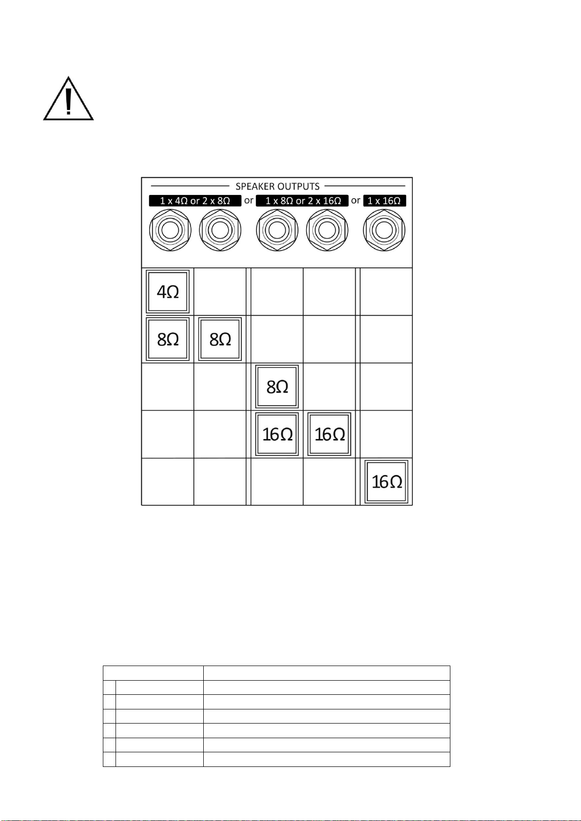
2.Speaker outputs
3.MIDI IN input
4.MIDI THRU/OUT output
5.EFS-1 footswitch input
6.FX LOOP signal -10dBu/+4dBV level switch
7.FX LOOP signal RETURN input
8.FX LOOP signal SEND output
-4-
Speaker connection
Connect speakers before use. Do not switch the amplifier on without a loudspeaker
connected. Check the impedance and power rating of your speakers. Connect a
speaker or speakers with a total power of 70W or more.
Connected speakers must provide impedance matching. The table below shows how to connect
the speakers according to their impedance. Impedance mismatch can activate overload protection
(see Troubleshooting section).
CLEAN/CRUNCH channel
The channel includes:
1. GAIN knob for channel gain adjustment
2. MODE indicator showing on/off status and mode of the channel
3. MODE switch for activating the channel and selecting the mode
4. BASS knob for low end tones adjustment
5. TREBLE knob for high tones adjustment
The channel has the following modes:
MODE
6
RED
+13dB boost, high compression
5
MAGENTA
+9dB boost, normal compression
4
YELLOW
+9dB boost, high compression
3
GREEN
+5dB boost, contour on, normal compression
2
CYAN
+5dB boost, contour on, high compression
1
BLUE
contour on, high compression

-5-
When CLEAN/CRUNCH channel is on, the output power LEVEL indicator shows current
power/volume level of CLEAN/CRUNCH channel (see OUTPUT POWER section).
OVERDRIVE channel
Channel includes:
1. GAIN knob for channel gain adjustment
2. MODE indicator showing on/off status and mode of the channel
3. MODE switch for activating the channel and selecting the mode
4. BASS knob for low end tones adjustment
5. MIDDLE know for mid range tones adjustment
6. TREBLE knob for high tones adjustment
The channel has the following modes:
MODE
6
RED
+16dB boost, high compression
5
MAGENTA
+8dB boost, normal compression
4
YELLOW
+10dB boost, high compression
3
GREEN
+3dB boost, normal compression
2
CYAN
+5dB boost, very high compression
1
BLUE
high compression
When OVERDRIVE channel is on, the output power LEVEL indicator shows current power/volume
level of OVERDRIVE channel (see OUTPUT POWER section).
FX LOOP section
AMBER 40 features a serial FX LOOP with signal level switch (see Back panel).
The -10dBu level should be used for stompbox-type effects, while the +4dBV level is for the rack-
type effects. RED colour of FX LOOP indicator means the FX Loop is active. Enabling/disabling of
the loop in the BLUE and CYAN modes (see Footswitch working modes) is done by footswitch
button or front panel FX LOOP switch (upwards). In the preset footswitch modes the status is
changed by front panel FX LOOP switch (upwards) and is stored as a preset parameter. This
allows to change the amp's sound and simultaneously switching on/off the effect plugged into the
FX LOOP.
STORE switch
STORE switch is used to store channel settings, presets and other settings of the amplifier. Short
flashing of indicators confirms saving.
REVERB knob
The REVERB knob is used for reverb-type effect volume control.

-6-
OUTPUT POWER section
Power/volume LEVEL switch allows to choose one of six power/volume levels:
LEVEL
dB
% of MASTER
OUTPUT POWER
e. g. for 10W
6
RED
0dB
100%
10.0W
5
MAGENTA
-0.7dB
85%
8.5W
4
YELLOW
-1.4dB
72%
7.2W
3
GREEN
-2.1dB
62%
6.2W
2
CYAN
-2.8dB
52%
5.2W
1
BLUE
-3.5dB
45%
4.5W
Power LEVEL determines the power/volume of the active channel.
The MASTER knob sets the overall power/volume in the range of 3W to 40W for RED
power/volume LEVEL.
Footswitch working modes
Footswitch EFS-1and AMBER 40 amp can operate in one of six modes:
FOOTSWITCH MODES
6
RED
4 banks with 6 presets
5
MAGENTA
4 banks with 4 presets
4
YELLOW
6 presets
3
GREEN
4 presets
2
CYAN
4 channels, FX LOOP
1
BLUE
2 channels, FX LOOP, SOLO
The features of push-buttons according to the footswitch mode:

-7-
Footswitch mode setting
1. Switch the amp on
2. Switch and keep LEVEL switch downwards and switch down the STORE switch. The blue
colour of FX LOOP indicator confirms the footswitch mode setting.
3. The CLEAN/CRUNCH MODE channel indicator shows the current mode.
4. Use CLEAN/CRUNCH MODE switch to set the chosen mode.
5. Use STORE switch to save the setting. Short flashing confirms saving.
6. Use any other switch to exit the setting mode.
For YELLOW and RED mode (with six presets) the OVERDRIVE channel MODE indicator shows
the SHIFT UP button way of working:
BLUE –pressing of SHIFT UP button switches immediately to corresponding active
button preset e.g. from preset P2 to preset P5, and then, if the chosen preset is different e.g. P6,
press the P3/6 button
RED -pressing of SHIFT UP button toggles the state of SHIFT UP indicator and
current preset indicator starts to blink, then one has to press the chosen preset button (e.g. P3/6).
The amp will switch directly from preset P2 to preset P6. Pressing of active preset button switches
immediately to corresponding active button preset e.g. from preset P2 to P5.
Blue footswitch mode –two channels, FX LOOP and SOLO
The footswitch push-buttons features:
CLEAN/CRUNCH
OVERDRIVE
FX LOOP
SOLO
switch-on the
CLEAN/CRUNCH
channel
switch-on the
OVERDRIVE channel
enable/disable
FX LOOP
enable/disable
SOLO option
Both CLEAN/CRUNCH and OVERDRIVE channels can operate in any of channel MODEs and
power/volume LEVELs for SOLO off and on option. The STORE switch saves both channels
setting for SOLO off and on option simultaneously.
Cyan footswitch mode –four channels and FX LOOP
The footswitch push-buttons features:
Ch1/3
Ch2/4
FX LOOP
SHIFT UP
switch-on the channel
Ch1 or Ch3
switch-on the channel
Ch2 or Ch4
enable/disable
FX LOOP
change of the channel
range
There are four channels: Ch1 and Ch2 when SHIFT UP is off, and Ch3 and Ch4 when SHIFT UP
is on. To each channel (Ch1 to Ch4) CLEAN/CRUNCH or OVERDRIVE channel can be assigned
as follows:
1. Use footswitch to select channel from Ch1 to Ch4
2. Use channel MODE switches to select channel and its mode
3. Use LEVEL switch to select power/volume level
4. Use STORE switch to save selected channel. Short flashing confirms saving.

-8-
Green footswitch mode –four presets
The footswitch push-buttons features:
P1
P2
P3
P4
switch-on
the preset P1
switch-on
the preset P2
switch-on
the preset P3
switch-on
the preset P4
The mode allows to save and recall the four presets. Each preset comprises:
- the chosen amp's channel and its MODE,
- the status of the FX LOOP,
- the power/volume LEVEL
To set and save the preset:
1. Press footswitch button to select preset P1 to P4
2. Use channel MODE switch to select channel and its mode
3. Use LEVEL switch to select power/volume level
4. Set FX LOOP status by front panel FX LOOP switch (upwards)
5. Use STORE switch (downwards) to save preset. Short flashing confirms saving.
Yellow footswitch mode –six presets
The footswitch push-buttons features:
P1/4
P2/5
P3/6
SHIFT UP
switch-on the
preset P1 or P4
switch-on the
preset P2 or P5
switch-on the
preset P3 or P6
presets range
shift
The mode allows to save and recall the six presets. Lit SHIFT UP indicator means P4 to P6
presets range. SHIFT UP button way of working is optional and is described in Footswitch mode
setting section.
Magenta footswitch mode –four banks of four presets
The footswitch push-buttons features:
P1
P2
P3
P4
switch-on
the preset P1
switch-on
the preset P2
switch-on
the preset P3
switch-on
the preset P4
press and hold the button for more than one second
bank B1
bank B2
bank B3
bank B4
The mode allows to save and recall the four presets in each of four banks. Pressing and holding
selected bank button for more than one second switches to the selected bank. Short flashing of
indicator confirms bank switching. Presets saving and recalling is identical to GREEN footswitch
mode.

-9-
Red footswitch mode –four banks of six presets
The footswitch push-buttons features:
P1/4
P2/5
P3/6
SHIFT UP
switch-on the
preset P1 or P4
switch-on the
preset P2 or P5
switch-on the
preset P3 or P6
presets range
shift
press and hold the button for more than one second
bank B1
bank B2
bank B3
bank B4
The mode allows to save and recall six presets in each of four banks. Pressing and holding
selected bank button for more than one second switch to selected bank. Short flashing of indicator
confirms bank switching. Presets saving and recalling is identical to YELLOW footswitch mode.
MIDI IN input
Note: Amp's MIDI control is active only in preset footswitch/amp modes (GREEN, YELLOW,
MAGENTA and RED). MIDI transmit channel of the control device must be the same as the MIDI
receive channel of the amplifier (see MIDI receive channel setting).
The control of the amplifier is done by using Program Change command. Program Change
command recalls the preset from amplifier’s memory.
To set and save the preset:
1. Send MIDI Control Change command with preset number from control device
2. Use channel MODE switch to select channel and its mode
3. Use LEVEL switch to select power/volume level
4. Set FX LOOP status by front panel FX LOOP switch (upwards)
5. Use STORE switch (downwards) to save preset
The amplifier has a memory of 128 presets. The presets in the range 1 to 50 are common with
footswitch presets (see the table below).
Footswitch mode
Footswitch button
1
2
3
4
Program Change Number
Green - 4 presets
1
2
3
4
Yellow - 6 presets
5
6
7
8
9
10
SHIFT UP
Magenta - 4 presets, Bank 1
11
12
13
14
Magenta - 4 presets, Bank 2
15
16
17
18
Magenta - 4 presets, Bank 3
19
20
21
22
Magenta - 4 presets, Bank 4
23
24
25
26
Red - 6 presets, Bank 1
27
28
29
30
31
32
SHIFT UP
Red - 6 presets, Bank 2
33
34
35
36
37
38
SHIFT UP
Red - 6 presets, Bank 3
39
40
41
42
43
44
SHIFT UP
Red - 6 presets, Bank 4
45
46
47
48
49
50
SHIFT UP

-10-
MIDI THRU/OUT output
The amplifier has MIDI THRU/OUT output, where received MIDI data are sent (THRU feature) and
where Program Change commands are sent by the amplifier (OUT feature).
The Program Change command is sent each time the preset is recalled by footswitch in GREEN,
YELLOW, MAGENTA or RED mode. The table above shows the preset numbers of Program
Change command. This allows control of e.g. multi-effects processor plugged to the amp's FX
Loop. Before use set the amp’s MIDI transmit channel (see MIDI transmit channel setting) same as
receive channel e.g. of multi-effects processor.
MIDI receive channel setting
1. Switch the amplifier off with the POWER switch.
2. Switch MODE switches of both channels and hold them in down position. Switch the
amplifier on. Cyan color of FX LOOP indicator confirms the setting of MIDI receive channel.
3. CLEAN/CRUNCH and OVERDRIVE channel MODE indicators shows the actual MIDI
receive channel (see the table below).
4. Set the chosen channel with the CLEAN/CRUNCH channel MODE switch.
5. Save the setting with the STORE switch. Short flashing confirms saving.
6. Use any other switch to exit the setting mode.
MIDI transmit channel setting
1. Switch the amplifier off with the POWER switch
2. Switch MODE switches of both channels and hold them in up position. Switch the amplifier
on. Green color of FX LOOP indicator confirms the setting of MIDI transmit channel.
3. CLEAN/CRUNCH and OVERDRIVE channel MODE indicators shows the actual MIDI
transmit channel (see the table below)
4. Set the chosen channel with the CLEAN/CRUNCH channel MODE switch
5. Save the setting with the STORE switch. Short flashing confirms saving.
6. Use any other switch to exit the setting mode.
MIDI channel number
CLEAN/CRUNCH
MODE indicator
OVERDRIVE
MODE indicator
1
BLUE
NOT LIT
2
CYAN
NOT LIT
3
GREEN
NOT LIT
4
YELLOW
NOT LIT
5
MAGENTA
NOT LIT
6
RED
NOT LIT
7
BLUE
BLUE
8
CYAN
BLUE
9
GREEN
BLUE
10
YELLOW
BLUE
11
MAGENTA
BLUE
12
RED
BLUE
13
BLUE
CYAN
14
CYAN
CYAN
15
GREEN
CYAN
16
YELLOW
CYAN
-11-
Memory lock and footswitch mode lock function
The access to channels and presets memory and footswitch mode change can be locked if
necessary.
1. Switch the amplifier off with the POWER switch
2. Switch FX LOOP and power LEVEL switches and hold them in up position. Switch the
amplifier on. Magenta colour of FX LOOP indicator confirms the setting.
3. MODE indicators shows the current lock function status (see the table below)
4. Set the chosen status using CLEAN/CRUNCH and OVERDRIVE MODE switches.
5. Save the setting with the STORE switch. Short flashing confirms saving.
6. Use any other switch to exit the setting mode.
channels and presets memory
footswitch mode change
CLEAN/CRUNCH MODE indicator
OVERDRIVE MODE indicator
unlock
BLUE
BLUE
lock
RED
RED
Default memory setting function
The function restores memory to its default setting:
- channels and presets
- footswitch/amplifier mode = GREEN
- MIDI receive channel =1
- MIDI transmit channel =1
- channel and presets Memory access = unlock
- footswitch mode change = unlock
1. Switch the amplifier off.
2. Switch both channels MODE, FX LOOP and power LEVEL switches and hold them in up
position. Switch the amplifier on. (We know, it is not easy to avoid unintended use.)
YELLOW colour of FX LOOP indicator confirms access to function.
3. Use the STORE switch to activate function.
4. Switch any of the other switches to exit function.
Troubleshooting
symptom
reason
solution
when you start playing there is
no sound and all amp
indicators blink in red
shortcut on the speaker output
switch off the amp and check
speaker cable and speaker
cabinet
when you start playing there is
no sound while the amp
switches off by itself and
switches on again
while you are playing the amp
stops to play and all amp
indicators blink in red
power amp overload
e.g. 4 ohm speaker connected
to 8 ohm or 16 ohm speaker
output
switch off the amp and check
the speaker impedance and
connect it to the proper socket
while you are playing laud
amps switches off by itself and
switches on again
while you are playing the
footswitch indicators blink at
random
footswitch connected to
speaker output
connect footswitch plug to the
proper socket
after switching on the amp,
all footswitch indicators are
not lit
footswitch not connected to
the proper socket

-12-
Specification
Amber 40 guitar head amp:
Guitar input impedance: 1Mohm
FX Loop: serial, switchable signal level -10dBu or +4dBV
SEND output impedance: 400ohm
RETURN input impedance: 100kohm
Footswitch input for EFS-1 footswitch
MIDI IN and MIDI THRU/OUT
Speaker outputs: 4ohm (or 2 x 8ohm), 8ohm (or 2 x 16ohm), 16 ohm
Output power: 40Wrms, recommended minimum speaker(s) power 70W
Mains input: 100-240Vac, 50/60Hz, 2.2A
Dimensions (W x D x H): 450 x 176 x 200mm
Weight: 7.0kg
EFS-1 Footswitch:
Cable length: 5m
Connector: Jack stereo
Controls: four push buttons and four red LED indicators with six modes of operation
Dimensions (W x D x H): 300 x 76 x 40mm
Weight: 0.85kg
Package content
1. Amber 40 guitar head
2. EFS-1 footswitch
3. Mains cord
4. User manual
Warranty Terms and Conditions
Evolution Amplification warrants that this product shall be free of any defects in materials or
workmanship, if used under normal operating conditions, to the original purchaser for a period of
one year from the date of purchase. This Warranty shall be applicable when You present the
defective Product along with the original sales receipt to the Authorised Dealer from whom the
Product was purchased. You must either ship or take the defective Product and your original sales
receipt to your Authorised Dealer. We shall only be responsible for the cost of returning your
defective Product to you if you are entitled to the terms of this Warranty.
Warranty does not cover:
- damage caused by negligence, modification, improper use, improper installation, incorrect
mains voltages or every day wear and tear,
- damage caused by repair or service carried out by unauthorized persons,
- damage occurring during shipment or transportation,
- product with a serial number which has been defaced, removed, altered or is illegible.

-13-
Table of Contents
Front panel
page 3
Back panel
page 3
Speaker connection
page 4
CLEAN/CRUNCH channel
page 4
OVERDRIVE channel
page 5
FX LOOP section
page 5
STORE switch
page 5
REVERB knob
page 5
OUTPUT POWER section
page 6
Footswitch working modes
page 6
Footswitch mode setting
page 7
Blue footswitch mode –two channels, FX LOOP and SOLO
page 7
Cyan footswitch mode –four channels and FX LOOP
page 7
Green footswitch mode –four presets
page 8
Yellow footswitch mode –six presets
page 8
Magenta footswitch mode –four banks of four presets
page 8
Red footswitch mode –four banks of six presets
page 9
MIDI IN input
page 9
MIDI THRU/OUT output
page 10
MIDI receive channel setting
page 10
MIDI transmit channel setting
page 10
Memory lock and footswitch mode lock function
page 11
Default memory setting function
page 11
Troubleshooting
page 11
Specification
page 12
Package content
page 12
Warranty Terms and Conditions
page 12

-14-
-15-
Vielen Dank, dass Sie sich für Evolution Verstärker entschieden haben. Wir sind stolz Ihnen
die neue einzigartige Technologie des Evolution Amber 40 zur Verfügung zu stellen. Wir sind
überzeugt Sie werden von dem klassischen Gitarrensound der Leistung und Funktionalität unseres
Produktes begeistert sein.
Genießen Sie das Spielen auf dem Evolution Amber 40,
Ihr Evolution Amps - Team
BITTE lies diese Bedienungsanleitung vor dem Einschalten sorgfältig durch
Dieses Symbol, wo immer es erscheint, warnt Sie vor gefährlicher, nicht isolierter
Spannung im Gehäuse – Spannung, die möglicherweise genügt, eine
Stromschlaggefahr darzustellen
Dieses Symbol, wo immer es erscheint, macht Sie auf wichtige Bedienungs- und
Wartungsanweisungen aufmerksam, die in beiliegenden Unterlagen zu finden
sind. Bitte lesen Sie das Handbuch.
WARNUNG! - Wichtige Sicherheitshinweise
VORSICHT!
RISIKO –ELEKRISHER SCHLAG!
ENTFERNEN SIE KEINE SCHRAUBEN!
NICHT ÖFFNEN!
Um die Gefahr von Feuer und elektrischen Stromschlägen auszuschliessen, setzen
sie das Gerät niemals Regen oder Feuchtigkeit aus und stellen sie keine
Flüssigkeitsbehälter (z. b. Vasen) darauf. Setzen Sie dieses Gerät nicht in der Nähe
von Wasser (z. b. Schwimmbecken) ein.
Warnung! Dieses Gerät darf nur an eine geerdete Steckdose angeschlossen
werden. Netzstecker ziehen, wenn das Gerät längere Zeit nicht benutzt wird, oder
ein Gewitter aufzieht.
Schütze alle Kabel und insbesondere das Netzkabel vor Tritten oder Abknicken
insbesondere an Kabeldurchführungen und an Steckern. Auch Belastungen der
Anschlußbuchsen können zu Defekten führen.
Blockieren oder verdecken Sie nicht die Lüftungsschlitze oder Öffnungen.
Nur mit einem trockenen Lappen reinigen.
-16-
Überlassen Sie alle Servicearbeiten qualifiziertem Wartungspersonal. Wartung ist
notwendig, wenn das Gerät auf irgendeine Weise beschädigt wurde, wie zum
Beispiel:
- wenn das Gehäuse beschädigt wurde oder das Gerät heruntergefallen ist,
- wenn das Stromführungskabel oder der Stecker beschädigt oder abgenutzt ist,
- wenn Flüssigkeit oder Gegenstände in das Gerät gelangt sind,
- wenn das Gerät Regen oder Feuchtigkeit ausgesetzt war,
- wenn das Gerät nicht ordnungsgemäß funktioniert, obwohl die
Bedienungsanleitung beachtet wurde
Belastung durch extrem hohe Lärmpegel kann zu dauerhaftem Gehörverlust führen.Die
Verwaltung zur Gesundheit und Sicherheit am Arbeitsplatz der US-Regierung (OSHA) hat die
folgenden zulässigen Lärmpegelbelastungen festgelegt:
Dauer pro Tag in Stunden
Lärmpegel dBA, langsame Reaktion
8
90
6
92
4
95
3
97
2
100
1,5
102
1
105
0,5
110
0,25 oder weniger
115
Laut der OSHA kann jede Belastung oberhalb der oben genannten zulässigen Grenzwerte zu
gewissen Hörverlusten führen. Sollte die Belastung die obenstehenden Grenzwerte übersteigen,
müssen beim Betrieb dieses Verstärkungssystems Ohrenstopfen oder Schutzvorrichtungen im
Gehörgang oder über den Ohren getragen werden, um einen dauerhaften Gehörverlust zu
verhindern. Um sich vor einer möglicherweise gefährlichen Belastung durch hohe
Schalldruckpegel zu schützen, wird allen Personen empfohlen, die mit Geräten arbeiten, die wie
dieses Verstärkungssystem hohe Schalldruckpegel erzeugen können, beim Betrieb dieses Geräts
einen Gehörschutz zu tragen.
Dieses Gerät ist mit einem durchgestrichenen Abfallbehälter Symbol
gekennzeichnet (nach 2002/96/EU-Richtlinie über Elektro- und Elektronik-
Altgeräte). Diese Kennzeichnung gibt an, dass dieses Elektrogerät vom Hausmüll
getrennt entsorgt werden mussDieses Produkt besteht aus Materialien, die
recycelt oder nach dem Gebrauch weiter verwendet werden können. Es muss in
einem zugelassenen Recyclingzentrum entsorgt werden, entsprechend den
Empfehlungen der WEEE (Waste Electrical and Electronic Equipment) Richtlinie in
Ihrem Land.

-17-
Der AMBER 40 ist ein Zweikanal-Gitarrenverstärker, analog gebaut nach klassischer
Röhrenverstärker Architektur unter Verwendung von Halbleiterkomponenten (Ausnahme Digitaler
Reverb). Die langjährige und intensive Analyse Klassischer Röhrenverstärker (Sound und
Technologie) machte es uns möglich, einen Verstärker zu entwickeln der über Nichtlinearität,
Kompression und einem für Röhrenverstärker typischen verzerrten Ton verfügt. Eine Besonderheit
des AMBER 40 ist die Endstufenverzerrung und das Steuersystem der Ausgangsleistung. Die
Lautstärkeänderung der übersteuerten Töne wird durch Änderung der Ausgangsleistung des
Verstärkers hergestellt. Die besondere Konstruktion der Transformatorendstufe erlaubt eine
konstante Ausgangsleistung für 4, 8 und 16 Ohm-Lautsprecher.
Der AMBER 40 verfügt über einen "CLEAN/CRUNCH" Kanal und einen "OVERDRIVE" Kanal.
Jeder dieser Kanäle verfügt über eine eigene passive EQ-Sektion und ist in der Lage, in einem von
sechs wählbaren Modi mit unterschiedlicher Kompression und Verstärkung zu arbeiten. Die
Möglichkeit, Kanal-Modi zu speichern erweitert die Vielfalt der verfügbaren Sounds während des
spielens. Die Power LEVEL Funktion (die auch gespeichert werden kann) macht es möglich, dass
der Benutzer die Lautstärke während der Wiedergabe steuern kann.
Der Verstärker ist mit einem hochwertigen digitalen Reverb, FX Loop, MIDI Eingang, MIDI
Ausgang und einem 4 Fach Fußschalter ausgestattet. Der auswählbare Fußschalter-Modus
ermöglicht es dem Spieler den Verstärker in verschiedenen Arbeitsweisen zu betreiben und diese
auf den Spieler individuell einzustellen und anzupassen. Es stehen sechs Modi zu Verfügung von
den einfachsten, wie z.B. in typischen Zweikanal-Verstärkern, bis hin zu Modi mit Bänken und
Presets. Der MIDI-Eingang ermöglicht es den Verstärker über einen MIDI-Controller zu steuern,
während der MIDI-Ausgang es ermöglicht den MIDI-Effekt direkt über den Verstärker zu steuern.
Frontpanel
Siehe Fig. 1 auf der Einband Innenseite der Bedienungsanleitung.
1. INPUT –Gitarreneingang
2. GAIN - CLEAN/CRUNCH Kanal- Regler für Verstärkung
3. MODE - CLEAN/CRUNCH Kanal- Modus Wahlschalter auf/ab
4. MODE - CLEAN/CRUNCH Kanal- LED Modus Statusanzeige
5. BASS - CLEAN/CRUNCH Kanal- Regler der Bassfrequenzen
6. TREBLE - CLEAN/CRUNCH Kanal- Regler der Hochtonfrequenzen
7. GAIN - OVERDRIVE Kanal- Regler für Verstärkung
8. MODE - OVERDRIVE Kanal- Modus Wahlschalter auf/ab
9. MODE - OVERDRIVE Kanal- LED Modus Statusanzeige
10. BASS - OVERDRIVE Kanal- Regler der Bassfrequenzen
11. MIDDLE - OVERDRIVE Kanal- Regler der Mittenfrequenzen
12. TREBLE - OVERDRIVE Kanal- Regler der Hochtonfrequenzen
13. FX LOOP - FX LOOP- LED Statusanzeige (ROT - aktiv)
14. FX / LOOP, STORE - Wahlschalter betätigung nach oben FX LOOP ein/aus, nach unten
ist Speichern
15. REVERB - Lautstärke des Reverb Effektes
16. LEVEL - Ausgangsleistungs Wahlschalter auf/ab
17. LEVEL - LED Statusanzeige der Ausgangsleistung
18. MASTER - Regler für Ausgangsleistung und Gesamtlautstärke
19. POWER- Netzschalter

-18-
Backpanel
Siehe Fig. 2 auf der Einband Innenseite der Bedienungsanleitung
1. Strom/Netzeingang
2. Lautsprecherausgänge
3. MIDI IN - Eingang
4. MIDI THRU / OUT - Ausgang
5. EFS -1 Fußschaltereingang
6. FX LOOP Signal -10dBu / + 4dBV Umschalter
7. FX LOOP Signal RETURN - Eingang
8. FX LOOP Signal SEND - Ausgang
Lautsprecheranschluss
Den Verstärker nicht ohne einen angeschlossenen Lautsprecher einschalten.
Überprüfen Sie die Impedanz und Leistung der Lautsprecher. Schließen Sie einen
oder mehrere Lautsprecher mit einer Gesamtleistung von min. 70W an.
Die Impedanz der angeschlossenen Lautsprecher muss eingehalten werden.
Die folgende Tabelle zeigt, wie Sie die Lautsprecher Impedanz entsprechend anschließen.
Nichteinhaltung der Impedanzen kann zum auslösen des Überlastschutz führen (siehe Sektion
FEHLERBEHEBUNG).

-19-
CLEAN/CRUNCH Kanal
Der Kanal beinhaltet:
1. GAIN - Regler zur Einstellung der Verstärkung
2. MODE - LED Statusanzeige zeigt an -Kanal Ein/Aus und -Modus des Kanals
3. MODE - Schalter zum aktivieren des Kanals und zur Auswahl des Modus
4. BASS - Regler zur Einstellung der Bassfrequenzen
5. TREBLE - Regler zur Einstellung der Höhenfrequenzen
Der Kanal hat die folgenden Modi:
MODUS
6
RED
+13dB boost, high compression
5
MAGENTA
+9dB boost, normal compression
4
YELLOW
+9dB boost, high compression
3
GREEN
+5dB boost, contour on, normal compression
2
CYAN
+5dB boost, contour on, high compression
1
BLUE
contour on, high compression
Wenn der CLEAN/CRUNCH Kanal eingeschaltet ist, zeigt die LED Statusanzeige LEVEL die
aktuelle Ausgangsleistung und Lautstärke des CLEAN/CRUNCH Kanals an (siehe Sektion
AUSGANGSLEISTUNG).
OVERDRIVE - Kanal
Der Kanal beinhaltet:
1. GAIN - Regler zur Einstellung der Verstärkung
2. MODE - LED Statusanzeige zeigt an -Kanal Ein/Aus und -Modus des Kanals
3. MODE- Schalter zum aktivieren des Kanals und zur Auswahl des Modus
4. BASS- Regler zur Einstellung der Bassfrequenzen
5. MIDDLE- Regler zur Einstellung der Mittenfrequenzen
6. TREBLE- Regler zur Einstellung der Höhenfrequenzen
Der Kanal hat die folgenden Modi:
MODUS
6
RED
+16dB boost, high compression
5
MAGENTA
+8dB boost, normal compression
4
YELLOW
+10dB boost, high compression
3
GREEN
+3dB boost, normal compression
2
CYAN
+5dB boost, very high compression
1
BLUE
high compression
Wenn der Overdrive Kanal eingeschaltet ist, zeigt die LED Statusanzeige LEVEL die aktuelle
Ausgangsleistung und Lautstärke des OVERDRIVE Kanals an (siehe Sektion
AUSGANGSLEISTUNG).
Sektion FX LOOP
Der AMBER 40 verfügt über einen seriellen FX LOOP mit Signalpegel-Schalter (siehe Verstärker
BACKPANEL). Der Signalpegel -10dBu sollte für Stompbox-Effektgeräte verwendet werden,
während der Signalpegel +4dBV für die Rack-Effekte ist.
Die rote Farbe der FX LOOP - LED Statusanzeige bedeutet, dass der FX Loop aktiv ist. Das
Aktivieren / Deaktivieren des LOOP im BLUE und CYAN Modus (siehe Sektion Fußschalter
Arbeitsmodi) wird per Fußschalter oder FX LOOP Wahlschalter am Frontpanel des Verstärkers

-20-
durchgeführt. In den Preset Arbeitsweisen des Fußschalters wird der Status vom FX LOOP-
Wahlschalter am Frontpanel geändert (nach oben) und zugleich als ein Preset Parameter
gespeichert. Dies ermöglicht es, den Klang des Verstärkers zu ändern und gleichzeitig das Ein-
und Ausschalten der in den FX LOOP angeschlossen Effekte.
STORE - Schalter
Der STORE-Schalter dient zum speichern der Kanaleinstellung und für alle anderen Einstellungen
des Verstärkers. Ein kurzes Blinken der LED Statusanzeige bestätigt das Speichern.
REVERB - Regler
Der REVERB-Regler dient der Lautstärkeregelung des Reverb Effektes.
Sektion AUSGANGSLEISTUNG
Der LEVEL-Schalter ermöglicht einen von sechs Leistungs-Lautstärke Pegel zu wählen:
LEVEL
dB
% of MASTER
OUTPUT POWER
e. g. for 10W
6
RED
0dB
100%
10.0W
5
MAGENTA
-0.7dB
85%
8.5W
4
YELLOW
-1.4dB
72%
7.2W
3
GREEN
-2.1dB
62%
6.2W
2
CYAN
-2.8dB
52%
5.2W
1
BLUE
-3.5dB
45%
4.5W
Der LEVEL bestimmt die Leistung und Lautstärke des aktiven Kanals oder PRESETS.
Der MASTER-Regler bestimmt die Gesamtleistung und Lautstärke im Bereich von 3W bis 40W im
Pegel RED.
Fußschalter Arbeitsmodi
Der Fußschalter EFS-1 kann in einem von sechs Modi am Amber40 betrieben warden:
Fußschalter Arbeitsmodi
6
RED
4 Bänke mit 6 Presets
5
MAGENTA
4 Bänke mit 4 Presets
4
YELLOW
6 Presets
3
GREEN
4 Presets
2
CYAN
4 Kanäle, FX LOOP
1
BLUE
2 Kanäle, FX LOOP, SOLO
Table of contents
Languages:


