Evolution Spas 6-1000 User manual

Acrylic Spa Owner’s Manual
Customer Service 1•800•787•6649
READ AND FOLLOW ALL INSTRUCTIONS
Unit is IPX5 Compliant

2
Congr tul tions on your purch se!
Your new spa will bring you years of
enjoyment and relaxation.
Please take the time to familiarize yourself with the safety precautions,
operational procedures, routine water maintenance and cleaning
so that your spa will provide a
healthy environment for all your bathers.
Enjoy!

Customer Service 1•800•787•6649 3
Contents
Important Safety Instructions and Warnings . . . . . . . . . . . . . . . . . . . . . . . . . . . . . . . . . . . . . . . . . . . . 4
Prepare for Your New Spa
Plan the Best Location . . . . . . . . . . . . . . . . . . . . . . . . . . . . . . . . . . . . . . . . . . . . . . . . . . . . . . . . . . . . . 6
Identifying the Spa’s Electrical Components . . . . . . . . . . . . . . . . . . . . . . . . . . . . . . . . . . . . . . . . . . . . 7
Electrical Installation (120 V 60HZ North America). . . . . . . . . . . . . . . . . . . . . . . . . . . . . . . . . . . . . . 8
120v to 240v Conversion (Plug & Play Models Only) . . . . . . . . . . . . . . . . . . . . . . . . . . . . . . . . . . . . . 9
Electrical Installation (240 V 60HZ North America). . . . . . . . . . . . . . . . . . . . . . . . . . . . . . . . . . . . . . 11
GFCI Wiring Diagram (240 V 60HZ North America). . . . . . . . . . . . . . . . . . . . . . . . . . . . . . . . . . . . . 12
GFCI Wiring Diagram (230 V 50HZ Europe) . . . . . . . . . . . . . . . . . . . . . . . . . . . . . . . . . . . . . . . . . . . 13
Operating Your Spa
Filling and Starting Up Your Spa . . . . . . . . . . . . . . . . . . . . . . . . . . . . . . . . . . . . . . . . . . . . . . . . . . . . . . 14
Priming the Pump . . . . . . . . . . . . . . . . . . . . . . . . . . . . . . . . . . . . . . . . . . . . . . . . . . . . . . . . . . . . . . . . . 15
Topside Control Panels. . . . . . . . . . . . . . . . . . . . . . . . . . . . . . . . . . . . . . . . . . . . . . . . . . . . . . . . . . . . . 16
Operational and Energy Tips. . . . . . . . . . . . . . . . . . . . . . . . . . . . . . . . . . . . . . . . . . . . . . . . . . . . . . . . . 19
Personal Settings (Jets, Air Controls, Diverters, Waterfalls) . . . . . . . . . . . . . . . . . . . . . . . . . . . . . . . 20
Maintaining Spa Water Quality
Testing and Adjusting Spa Water . . . . . . . . . . . . . . . . . . . . . . . . . . . . . . . . . . . . . . . . . . . . . . . . . . . . . 21
Chemical Balance, Ozonator, Sanitation, Filtration . . . . . . . . . . . . . . . . . . . . . . . . . . . . . . . . . . . . . . . 21
Filter Cleaning . . . . . . . . . . . . . . . . . . . . . . . . . . . . . . . . . . . . . . . . . . . . . . . . . . . . . . . . . . . . . . . . . . . . 23
Maintenance Schedule . . . . . . . . . . . . . . . . . . . . . . . . . . . . . . . . . . . . . . . . . . . . . . . . . . . . . . . . . . . . . . 23
Vacation Care . . . . . . . . . . . . . . . . . . . . . . . . . . . . . . . . . . . . . . . . . . . . . . . . . . . . . . . . . . . . . . . . . . . . 24
Chemical Safety . . . . . . . . . . . . . . . . . . . . . . . . . . . . . . . . . . . . . . . . . . . . . . . . . . . . . . . . . . . . . . . . . . . 24
Cleaning and Care
Draining Your Spa . . . . . . . . . . . . . . . . . . . . . . . . . . . . . . . . . . . . . . . . . . . . . . . . . . . . . . . . . . . . . . . . . 25
Cleaning Your Spa . . . . . . . . . . . . . . . . . . . . . . . . . . . . . . . . . . . . . . . . . . . . . . . . . . . . . . . . . . . . . . . . . 25
Removing and Reseating the Pillows . . . . . . . . . . . . . . . . . . . . . . . . . . . . . . . . . . . . . . . . . . . . . . . . . . . 25
Spa Cover . . . . . . . . . . . . . . . . . . . . . . . . . . . . . . . . . . . . . . . . . . . . . . . . . . . . . . . . . . . . . . . . . . . . . . . . 26
Sound System . . . . . . . . . . . . . . . . . . . . . . . . . . . . . . . . . . . . . . . . . . . . . . . . . . . . . . . . . . . . . . . . . . . . . 26
Winterizing . . . . . . . . . . . . . . . . . . . . . . . . . . . . . . . . . . . . . . . . . . . . . . . . . . . . . . . . . . . . . . . . . . . . . . . 27
Troubleshooting
Water Quality Problems. . . . . . . . . . . . . . . . . . . . . . . . . . . . . . . . . . . . . . . . . . . . . . . . . . . . . . . . . . . . . 29
Operational Problems. . . . . . . . . . . . . . . . . . . . . . . . . . . . . . . . . . . . . . . . . . . . . . . . . . . . . . . . . . . . . . . 30
Control Pack Codes . . . . . . . . . . . . . . . . . . . . . . . . . . . . . . . . . . . . . . . . . . . . . . . . . . . . . . . . . . . . . . . . 39
Product Registration. .. . . . . . . . . . . . . . . . . . . . . . . . . . . . . . . . . . . . . . . . . . . . . . . . . . . . . . . . . . . . . . . 43
CONTACT INFORMATION
For customer service, please call 1-800-787-6649
Strong™ Industries
3204 Point Township Drive, Northumberland, PA 17857 USA
The m nuf cturer reserves the right to m ke product modific tions nd enh ncements without notice.
Specific tions nd dimensions re pproxim te nd for reference only.
4
Important Safety Instructions and Warnin s
Warning: Children should not use
spas or hot tubs without adult supervi-
sion.
Avertissement: Ne pas laisser les enfants
utiliser une cuve de relaxation sans surveillance.
Warning: Do not use spas or hot tubs
unless all suction guards are installed to
prevent body and hair entrapment.
Avertissement: Pour éviter que les cheveux
ou une partie du corps puissent étre aspirés, ne
pas utiliser une cuve de relaxation si les grilles
de prise d’aspiration ne sont pas poutes en
place.
Warning: People using medications
and/or having an adverse medical his-
tory should consult a physician before
using spa or hot tub.
Avertissement: Les personnes qui prennet
des medicaments ou ont des problemes de
sante devraient consulter un medicin avant d’
utiliser une cuve de relaxation.
Warning: People with infectious dis-
eases should not use a spa or hot tub.
Avertissement: les personnes at-
teintes de maladies infectieuses ne devraient
pas utiliser une cuve de relaxation.
Warning: To avoid injury, exercise
care when entering or exiting the spa
or hot tub.
Avertissement: Pour éviter des blessures,
user de prudence en entrant dans une cuve de
relaxation en sortant.
Warning: Do not use drugs or alcohol
before or during the use of a spa or
hot tub, to avoid unconsciousness and
possible drowning.
Avertissement: Pour éviter l’évanouissement
et la noyade éventuelle, ne prendre ni drogue ni
alcool avant d’utiliser une cuve de relaxation ni
quand on s’y trouve.
Warning: Pregnant or possibly preg-
nant women should consult a physician
before using a spa or hot tub.
Avertissement: Les femmes enceintes, que
leur grossesse soit confirmée ou non, devraient
consulter un médecin avant d’utiliser une.
Warning: Water temperature in ex-
cess of 38°C may be injurious to your
health.
Avertissement: Il peut etre dangereux pour la
sante de se plonger dans de l’eau a plus de
38°C.
Warning: Before entering the spa or
hot tub, measure the water tempera-
ture with an accurate thermometer.
Avertissement: Avant d’utiliser une cuve de
relaxation mesurer la température de l’eau á
l’aide d’un thermométre précis.
Warning: Do not use a spa or hot tub
immediately following strenuous exer-
cise.
Avertissement: Ne pas utiliser une cuve de
relaxation immédiatement aprés un exercise
fatigant.
READ AND FOLLOW ALL INSTRUCTIONS
SAVE THESE INSTRUCTIONS
To reduce the risk of injury, do not permit children to use this
product unless they are closely supervised at all times.
!
!
!
!
!
!
!
!
!
!

Customer Service 1•800•787•6649 5
Important Safety Instructions and Warnin s
Warning: Prolonged immersion in a
spa or hot tub may be injurious to your
health.
Avertissement: L’utilisation prolongee d’ une
cuve de relaxation peut etre dangereuse pour la
sante.
Warning: Do not permit or use elec-
tric appliances (such as a light, tele-
phone, radio or television) within 1.5
meters of spa or hot tub.
Avertissement: Ne pas placer d’appareil élec-
trique (luminaire, téléphone, radio, téléviseur,
etc.) á moins de 1.5 meters de cette cuve de
relaxation.
Caution: Maintain water chemistry in
accordance with the manufacturer’s in-
structions.
Attention: La teneur de l’eau en matiéres dis-
soutes doit étre conforme aux directives du
fabricant.
Caution: In order to avoid a hazard
due to inadvertent resetting of the
thermal cut-out, this appliance must
not be supplied through an external switching
device, such as a timer, or connected to a cir-
duit that is regularly switched on and off by the
utility.
HYPERTHERMIA
Hyperthermia occurs when the inter-
nal temperature of the body reaches a
level several degrees above the normal body
temperature of 37°C. The symptoms of hyper-
thermia include:
1) Unawareness of impending hazard;
2) Failure to perceive heat;
3) Failure to recognize the need to exit the spa
or hot tub;
4) Physical inability to exit the spa or hot tub;
5) Fetal damage in pregnant women; and
6) Unconsciousness and resulting in the danger
of drowning.
Warning: The use of alcohol or drugs
can greatly increase the risk of fatal hy-
perthermia in hot tubs or spas.
Avertissement: La consommation d’ alcool
ou de drogue augmente considerablement.
Warning: The appliance is not to be
used by persons (including children)
with reduced physical, sensory or men-
tal capabilities, or lack of experience and knowl-
edge, unless they have been given supervision
or instruction.
READ AND FOLLOW ALL INSTRUCTIONS
SAVE THESE INSTRUCTIONS
To reduce the risk of injury, do not permit children to use this
product unless they are closely supervised at all times.
!!
!
!
!
!
!

6
Prepare for Your New Spa
Prepare for Your New Spa
Most cities and counties require permits for exte-
rior construction and electrical circuits. In addition,
some communities have codes requiring residential
barriers such as fencing and/or self-closing gates on
property to prevent unsupervised access to the
property by children. See codes, page 7. Your local
code enforcement officer can provide information
on which permits may be required and how to ob-
tain them prior to the delivery of your spa.
Prepare a Good Foundation
Damage caused by an inadequate or improper
foundation is not covered by the warranty. The
spa owner is responsible for providing a proper
foundation. Place the spa on a solid, level founda-
tion. If you are installing the spa indoors (not rec-
ommended), pay close attention to the flooring
beneath it. Choose flooring that will not be dam-
aged or stained. If you are installing your spa on an
elevated wood deck or other structure, consult a
structural engineer or a contractor to ensure the
structure will support the weight of 150 pounds per
square foot. An adequate drainage system has to be
provided to deal with overflow water.
Plan the Best Location
SAFETY FIRST
Do not place your spa within 10 feet (3 m)
of overhead power lines.
Consider Spa Use
How you intend to use your spa will help you
determine where you should position it. For exam-
ple, will you use your spa for recreational or thera-
peutic purposes? If your spa is mainly used for family
recreation, be sure to leave plenty of room around
it for activity. If you will use it for relaxation and
therapy, you will probably want to create a specific
mood around it.
Climate, Privacy and View
Place the spa near a house entry if you live in a
snowy or rainy environment so you have a place to
comfortably change clothes. Consider seasonal
changes, too. Bare trees don’t provide much privacy.
And don’t forget to think of your neighbors’ view of
you, and your view of your neighbors.
Keep Your Spa Clean
In planning your spa’s location, consider a location
where there is a clean path to and from the house.
Use a mat at the spa’s entrance to encourage
bathers to clean their feet before entering your spa.
Allow for Service Access
If you are installing your spa near a wall or with any
type of structure on the outside, such as a gazebo,
remember to allow a minimum of 18” access for
service.
!

Customer Service 1•800•787•6649 7
Prepare for Your New Spa
Spa Model No. Usage Description and ettings uggested
GFCI ize*
Wire(s)
Required
Model No.
6-0000, 6-0001, 6-1000, 6-1001, 6-1002, 6-1010, 6-1011,
6-1012, 6-1100, 6-1101, 6-1102, 6-1110, 6-1111, 6-1112
1 pump spa
or
1-pump spa + blower
(Pump on hi + heat)
240V
40 AMP
#6 AWG
Copper
Model No.
6-2001, 6-2002, 6-2011, 6-2012, 6-2101, 6-2102, 6-2111, 6-2112,
2 pump (one 2-speed & one 1-speed)
(Pump on hi + heat)
or
2 pump spa + blower
240V
50 AMP
#6 AWG
Copper
Model No.
6-3001, 6-3002, 6-3011, 6-3012, 6-3101, 6-3102, 6-3111, 6-3112,
6-4001, 6-4002, 6-4011, 6-4012, 6-4101, 6-4102, 6-4111, 6-4112
3 pump spa
or
3 pump spa + blower
or
4 pumps
240V
60 AMP
#6 AWG
Copper
Model No. G 500 (L1, N1)
5-100, 5-1000
5-101, 5-1001
1 pump European pa 230V
13 AMP
#6 AWG
Copper
Model No. G 500 (L1, N1, L2, N2)
5-100, 5-1000, 5-1010, 5-1100, 5-1110
5-101, 5-1001, 5-1011, 5-1101, 5-1111
1 pump European pa 230V
40 AMP
#6 AWG
Copper
Model No. G 520 Z (L1, N1, L2, N2)
5-2001, 5-2003, 5-2011, 5-2013, 5-2101, 5-2103, 5-2111, 5-2113
5-3001, 5-3003, 5-3011, 5-3013, 5-3101, 5-3103, 5-3111, 5-3113
2 pump European pa 230V
40 AMP
#6 AWG
Copper
Identifying the Spa’s Electrical Components
ocate Electrical Pack Part
Number and Model Number
on the metal plate mounted on out-
side of spa panel.
Certifications:
Spas, US:
ETL #101138129TOR-001B
Spas, Europe:
CE #3180220
Spa Covers:
ASTM #F1346
*Note: GFCI is required. Suggested size wi ensure proper operation. Exact Rating wi appear on unit’s meta ID Tag.
Model No.
6-0000, 6-0001
1 pump spa
plug and play
120V
15 AMP
#14 AWG
Outlet
8
Prepare for Your New Spa
120 Volt Electrical
Installation
(Plug & Play models
only)
(North America 60hZ)
Always follow applicable local, state and
federal codes and guidelines.
• On existing dedicated* electrical service, a 15A
breaker will work with no other appliances/acces-
sories on that line.
•
•
On new electrical service, usage of a 20A breaker
on a dedicated* line is recommended with no
other appliances/accessories on that line.
Cord-and-plug connections may not use a cord
longer than 15 feet (4.6 m) and must be plugged
into a dedicated 15A GFCI connection (NEC
680.42(A)
• Do not use extension cords!
• Always use a weatherproof-covered receptacle.
•
•
Receptacle shall be located not less than 5 feet
(1.5 m) from and not exceeding 10 feet (3.0 m)
from the inside wall of the spa. (NEC 680.43(A))
Do not bury the power cord. If your cord be-
comes damaged, replace it before next usage.
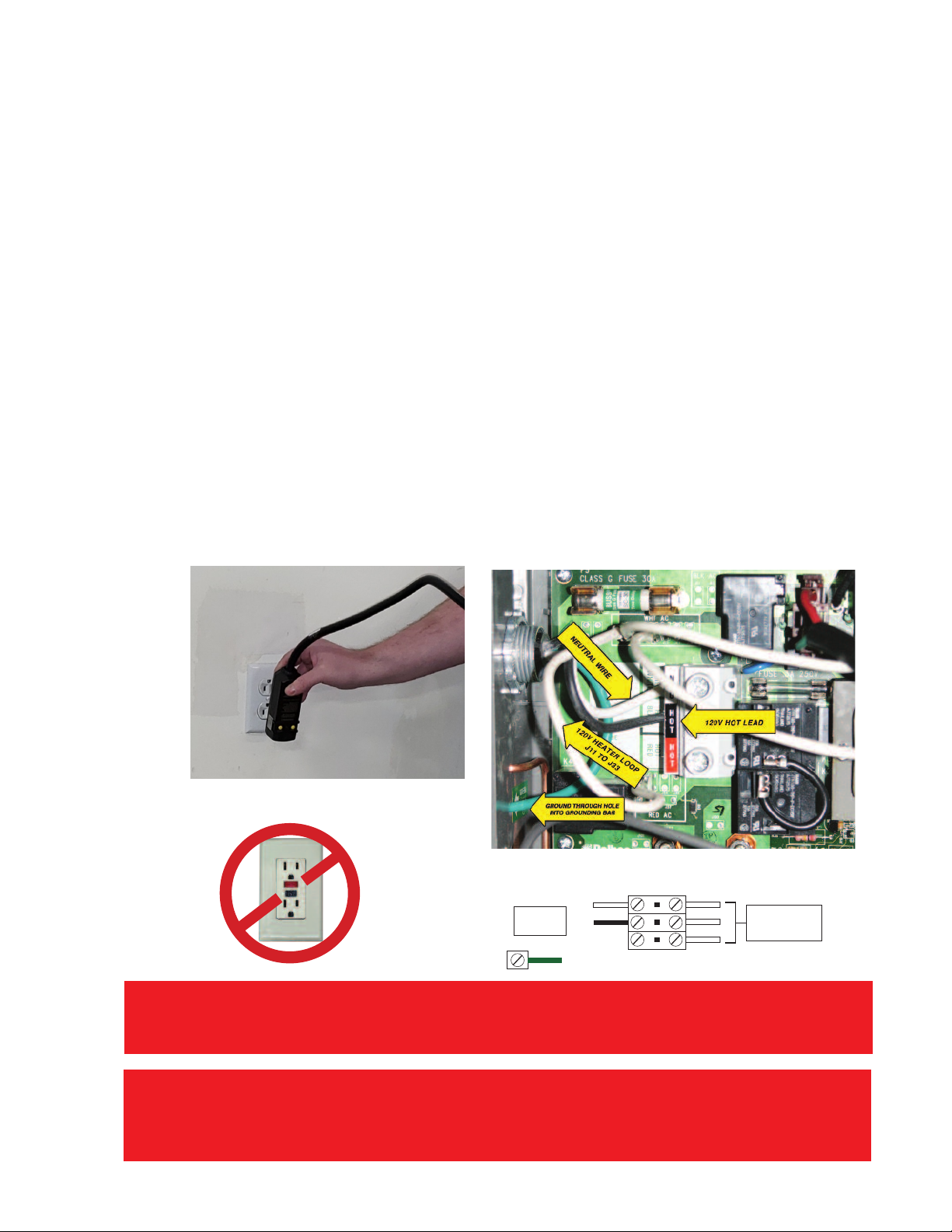
• All 120V spas come with a GFCI cord installed.
•Test the GFCI plug prior to first use and periodi-
cally when the spa is powered. To test the GFCI
plug version, follow these instructions. (Spa should
already be plugged in and operational.)
1. Press the TEST button on the GFCI. The GFCI will
trip and the spa will stop operating.
2. Press the RESET button on the GFCI. The GFCI
will reset and the spa will turn back on.
The spa is now safe to use.
• If the GFCI trips while the spa is in use, press the
RESET button. If the GFCI does not reset, unplug
the spa and call your local spa dealer for service.
DO NOT USE THE SPA!
DO NOT USE A
GFCI OUTLET with
a GFCI CORD!
L1
L2
N
GRND
THREE WIRE
& GROUND
THESE WIRES GO
TO THE PC BOARD
CONTROL CIRCUIT
HOT BLACK
NEUTRAL
120V
*IF U ING THE TANDARD 120V ERVICE, YOU MU T U E A DEDICATED LINE, WHICH MEAN THAT THERE
CANNOT BE ANY OTHER HOU EHOLD ITEM CONNECTED TO THE CIRCUIT OR OUTLET AT ALL! HAVING
ANY OTHER ELECTRICAL APPLIANCE AT ALL ON THI CIRCUIT WHILE THE PA I RUNNING WILL TRIP
THE BREAKER IMMEDIATELY. DO NOT U E ANY TYPE OF EXTEN ION CORD BETWEEN THE PA AND THE
WALL OUTLET, THI WILL AL O CAU E THE BREAKER TO TRIP AND CAN BE A POTENTIAL FIRE HAZARD.
*IF A GFCI OUTLET IS PRESENT, EITHER THE GFCI CORD OR OUTLET WILL NEED TO BE REPLACED.
CHECK WITH LOCAL CODE OFFICIALS ON OUTDOOR OUTLET REQUIREMENTS. IF GFCI OUTLET IS
REQUIRED, CORD GFCI MUST BE REMOVED AND A NON-GFCI CORD USED. ONLY ONE INLINE GFCI CAN BE
USED IN THE SPA CIRCUIT.

Customer ervice 1•800•787•6649 9
Prepare for Your New Spa
120V to 240 V
Conversion
(Plug & Play Models
only)
(North America 60hZ)
Some spa owners choose to have their spa con-
verted from 120V operation to 240V operation for
greater energy efficiency.
ARNING: The electrical circuit must
!be installed by a licensed electrical con-
tractor and approved by a local building
or electrical inspector. Customer must provide a
disconnect in the fixed wiring.
Failure to comply with state and local codes
may result in fire or personal injury and will be
the sole responsibility of the spa owner.
The steps to converting your spa from 120V
to 240V operation are shown below and must
be completed by a licensed electrician.
Power supply installation must include a properly
rated GFCI circuit breaker. The circuit must be dedi-
cated and should not be shared with any other ap-
pliances. It should be labeled and easily accessible to
users. The power supply must be hard wired into
the power pack. A hole may be drilled through the
spa cabinet near the electrical pack to accommo-
date wiring. Foam insulation may be sprayed around
the hole to fill any gaps between the cabinet and the
wiring.
Step 1.
Remove power
from the spa
Step 2.
Disconnect jumper
from WHT AC.
Step 3.
Disconnect other end of same
jumper from RED AC.
DO NOT DISCONNECT ANY OTHER
JUMPERS!
Note: All connectors in WHT AC are
interchangeable and the same is true of
all connections in RED AC.

10
Prepare for Your New Spa
PLEA E CHECK YOUR LOCAL BUILDING CODE AND ONLY U E A CERTIFIED ELECTRICIAN TO
IN TALL ANY ELECTRICAL COMPONENT TO YOUR PA.
Step 4.
Turn Dip switch #10 off (down).
All other Dip switches should remain
the same unless mode change is to be
enabled.
Mode change VS300FL4
Mode change VS501Z
Step 7.
After all other steps have been
completed, follow all instructions
for a 240 volt install.
Step 5. (optional)
Enable mode change.
A plug and play spa comes from the
factory locked in standard mode so
that the mode cannot be changed. To
enable mode change, a dip switch
must be turned to the off (down)
position. Depending on the model of
spa pack within the spa, the specific
dip switch that would need to be
changed will vary. If you have a
VS501z spa pack, you will turn dip
switch 2 off (down). If you have a
VS300 spa pack you will turn dip
switch 7 off (down).
Step 6.
Remove 120 volt GFCI cord.
A plug and play spa comes from the
factory with 120 volt GFCI cord
installed. To hook the spa up to 240
volts, the 120 volt GFCI cord must
first be removed.

11
240 Volt Electrical
Installation
(North America 60hZ)
WARNING:
The electrical circuit must be installed
by an electrical contractor and ap-
proved by a local building or electrical
inspector. Customer must provide a disconnect
in the fixed wiring.
Failure to comply with state and local codes
may result in fire or personal injury and will be
the sole responsibility of the spa owner.
Improper installations present
hazards which can result in personal
injury or property damage and void the war-
ranty on the spa.
Spa jumpers and dip switches are
preconfigured for a 240V installation.
• All 240V spas must be permanently hardwired to
the power supply. See US wiring diagram on page
9, European wiring diagram on page 10.
• Spas must be wired using this procedure. Any vari-
ance from these instructions will void your war-
ranty and may result in serious injury.
• When installed in the United States, the electrical
wiring of this spa must meet the requirements of
National Electric Code, ANSI/NFPA 70-2008 and
any applicable local, state, and federal codes.
GFCI and Wiring Requirements
• The power supplied to the spa must be on a dedi-
cated GFCI protected circuit as required by ANSI/
NFPA 70 with no other appliances or lights
sharing the power.
• Use copper wire with THHN insulation. Do not
use aluminum wire.
• When NEC requires the use of wires larger than
#6 AWG, install a junction box near the spa and
use #6 AWG wire between the junction box and
the spa.
• Wire runs over 85 feet must increase wire gauge
to the next lower number.
• Means for disconnection must be incorporated in
the fixed wiring in accordance with the wiring
rules.
Testing the GFCI Breaker
Test the GFCI breaker prior to first use and periodi-
cally when the spa is powered. To test the GFCI
breaker follow these instructions
1. With spa operating, press the TEST button on the
GFCI. The GFCI will trip and the spa will shut off.
2. Reset the GFCI breaker by switching the breaker
to the full OFF position, wait a moment, then turn
the breaker back on. The spa should have power
again.
!
Point of Entry for Electric Service
Installations can vary greatly from spa to spa, there-
fore the manufacturer does not have any pre-deter-
mined entry points for electrical service. The
installer will need to determine the best point of
entry, and create an entry point. Any of the 4 walls
or the spa base can be drilled through to make this
access point. Prior to drilling, be sure that there are
no components on the interior of the cabinet that
will possibly be damaged or in the way while making
the hole. The manufacturer recommends that some
form of moisture barrier is used at the hole to pre-
vent water from entering the spa. As long as all the
above criteria are met, this will in no way void the
warranty that is included with the spa.
Prepare for Your New Spa

12
Prepare for Your New Spa
4:45&.# 09
ON ON ON ON ON
OFF OFF OFF OFF OFF
RED (HOT)
BLACK (HOT)
WHT
GRN
FRONT VIEW OF TYPICAL G.F.C.I.
G.F.C.I. Breaker Box
House Breaker Box
GRN (GROUND)
GRN (GROUND)
GRN (GROUND)
WHT (NEUTRAL)
RED (HOT)
RED (HOT)
BLK (HOT)
BLK (HOT)
WHT
WHT
ON
OFF
LOAD
OUT
(BLK)
LOAD
OUT
(RED)
(3/
8)5
3&%
#-,
Neutral HotHotGround
USE COPPER 240V
WIRE MIN 6 AWG
RED (HOT)
FROM SPA
BLK (HOT)
FROM SPA
WHT
FROM SPA
WHT
BOTTOM VIEW OF
TYPICAL G.F.C.I.
ON
OFF
SPA CIRCUIT BOARD
L1
L2
N
GRND
THREE WIRE
& GROUND
THESE WIRES GO
TO THE PC BOARD
CONTROL CIRCUIT
240V
GFCI Wiring Diagram (North America 240V 60hZ)
WARNING:
The electrical circuit must be installed by an electrical con-
tractor and approved by a local building or electrical inspec-
tor. Failure to comply with state and local codes may result in fire or
personal injury and will be the sole responsibility of the spa owner.
Customer must provide a disconnect in the fixed wiring.
Improper installations present hazards which can result in per-
sonal injury or property damage and void the warranty on the spa.
!
IF THE NEUTRAL WIRE FROM THE SPA
IS NOT CONNECTED DIRECTLY INTO
THE LOAD NEUTRAL LUG ON THE GFCI
BREAKER, THE BREAKER WILL TRIP
CONSTANTLY. IF YOUR GFCI BREAKER
DOES NOT HAVE A LOAD NEUTRAL
LUG AND PIGTAIL WIRE, IT CANNOT
BE USED WITH THE SPA.

13
Single Service, TN an TT Electrical Systems
3 Wires (1 Line + 1 Neutral + 1 Protective Earth)
Protective Earth wire 6mm2 minimum
(Green/Yellow) must be connecte to system groun
terminal as marke .
This option is configured and shipped as the default.
All equipmen (pumps, blower, and hea er) runs on
service line L1.
Systems using only 1 DIP switch (A10) for heat disable:
• For 1 x 16 Amp Service:
DIP Switch A10 must be ON.
• For 1 x 32 Amp Service:
Set DIP Switch A10 such that total system amperage
draw never exceeds rated service input.
Systems using multiple DIP switches for heat disable:
•Refer to Switchban settings on inside cover of
pac .
Dual Service, TN an TT Electrical Systems
5 Wires (2 Lines + 2 Neutrals + 1 Protective
Earth)
Protective Earth wire 6mm2 minimum
(Green/Yellow) must be connecte to system groun
terminal as marke .
The hea er runs on service line L1, while all o her equip-
men , such as pumps and blowers, run on service line
L2.
Completely remove the white wire from J26 and J32.
No e: J32 and J25 are elec rically iden ical. The whi e
wire may be a ached o ei her erminal before removal.
Systems using only 1 DIP switch (A10) for heat disable:
• DIP Switch A10 must be OFF.
Systems using multiple DIP switches for heat disable:
•Refer to Switchban settings on inside cover of
pac .
GFCI Wiring Diagram (European 230V 50hZ)
Systems with PCB Rev B Only
Note: A residual current device with a tripping current rated not more than 30 mA
has to be installed in addition to local requirement. Customer must provide a disconnect in the fixed wiring.
Protective device for power connection must be on all phase conductors based on local requirements.
Note: A residual current device with a tripping current rated not more than 30 mA has to be installed
in addition to local requirement. Customer must provide a disconnect in the fixed wiring.
Protective device for power connection must be on all phase conductors based on local requirements.
For Certi ied Electrical Personnel re erence ONLY!
Prepare for Your New Spa

14
Operate Your Spa
Filling and Starting
1. Place spa on an approved surface and have it
properly wired by a licensed electrician.
2. Before filling spa test spa's electrical. Do not
allow electrical to remain on longer than 30
seconds. If PR is displayed, tun off spa and fill.
Locate drain hose before filling.
3. Remove exterior spa panel near Service Access
side
4. Make sure plumbing unions are secure and did
not loosen during shipping. There will be 4
unions on a 1-pump spa; 6 unions on a 2-pump
spa; and 8 unions on a 3-pump spa. Hand-
tighten any loose unions.
5. Verify all gate valves
in the equip-ment
area are open.
Before operation,
these valves must
be in the UP/
OPEN po-sition
and have plastic
clips in-serted.
Never run the spa
with the gate
valves closed or
without water
circulating for any
period of time.
6. Remove the filter(s) (weir and basket also, if
equipped) from filter chamber. Photos may vary
from your particular spa model.
7. All of our spas are winterized using a
biodegrad-able antifreeze in case a spa were to
sit idle in cold weather prior to initial use. Use
a garden hose to rinse your spa with regular
tap water. The hose should be placed over jets
and filter canister to push out any remaining
antifreeze from the lines. Fill the foot well
completely and drain using the guidelines stated
in the “Draining Your Spa” section. Repeat this
step if water draining out does not appear to
be clear.
Place a garden hose in the filter chamber and fill
your spa with regular tap water to 2” higher than
the highest jet (excluding neck / shoulder jets). If
the water is too high, it will overflow when people
enter the bathing area. If the water is too low, air
will enter through the fil-ter and possibly cause
airlock or even damage to the unit over time.
Install the filter(s) (weir and basket, if equipped)
into the filter chamber.
Once the water is at the correct level , turn on the
power at the GFCI breaker.
Note: When the power is turned on, the controls will
per-form di gnostic check for few minutes. When
com-plete, the sp will utom tic lly oper te t filter
speed nd continue he ting until w ter re ches 100ºF.
If water does not flow from jets when the pump is
running, there could be an air pocket. See Priming
the Pump, for methods of removing air pockets
from the pump(s).
PRESSURE
UNION
SUCTION
UNION
8.
9.
10.
11.

Customer Service 1•800•787•6649 15
Operate Your Spa
Priming the Pump
Sometimes air can become trapped in the pump
while filling the spa. You will know this has happened
when after you have filled and started the spa, the
pump does not function. You will hear the pump op-
erating, but no or little water will be moving. The
pump will not work properly while air is trapped
in it. Con-tinuing to operate the pump in this
way will cause damage.
New spa owners often have difficulty the first time
they start their spa and the pump fails to prime. This
can be frustrating, but these simple instructions can
help you.
To remove small air bubbles trapped in the
pump.
1. Turn the spa on and wait for PR (Priming Mode)
to appear on the topside display.
2. Press the JETS1 button to turn on the
pump and let it run for 10 seconds. The
pump should be running on low speed.
3. Press the JETS1 buttons again and let the pump
run on high speed for 10 seconds.
4. Press the JETS1 button again to turn off the
pump. The pump should be left in the off position
for 10 to 15 seconds.
5. Repeat steps 1 through 4 until water is flowing
through all the jets and all air is removed from the
plumbing.
To remove a large air lock within the pump:
1. Turn off power at the breaker.
2. Remove the spa panel closest to the pump.
3. Loosen the Pressure Union on top of the pump
by hand or with a strap wrench. You may hear
a
hissing sound or see bubbles . Eventually you will be
left with a solid stream of water. When air is bled
out, tighten the union, turn breaker on and set the
pump on high speed.

16
Operate Your Spa
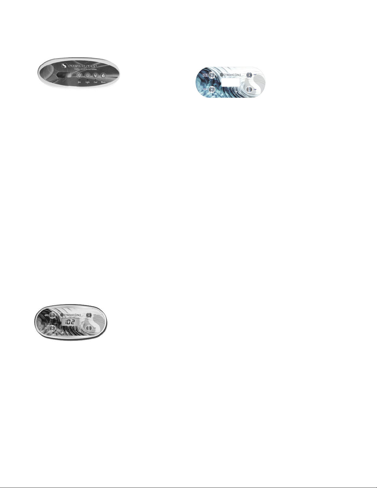
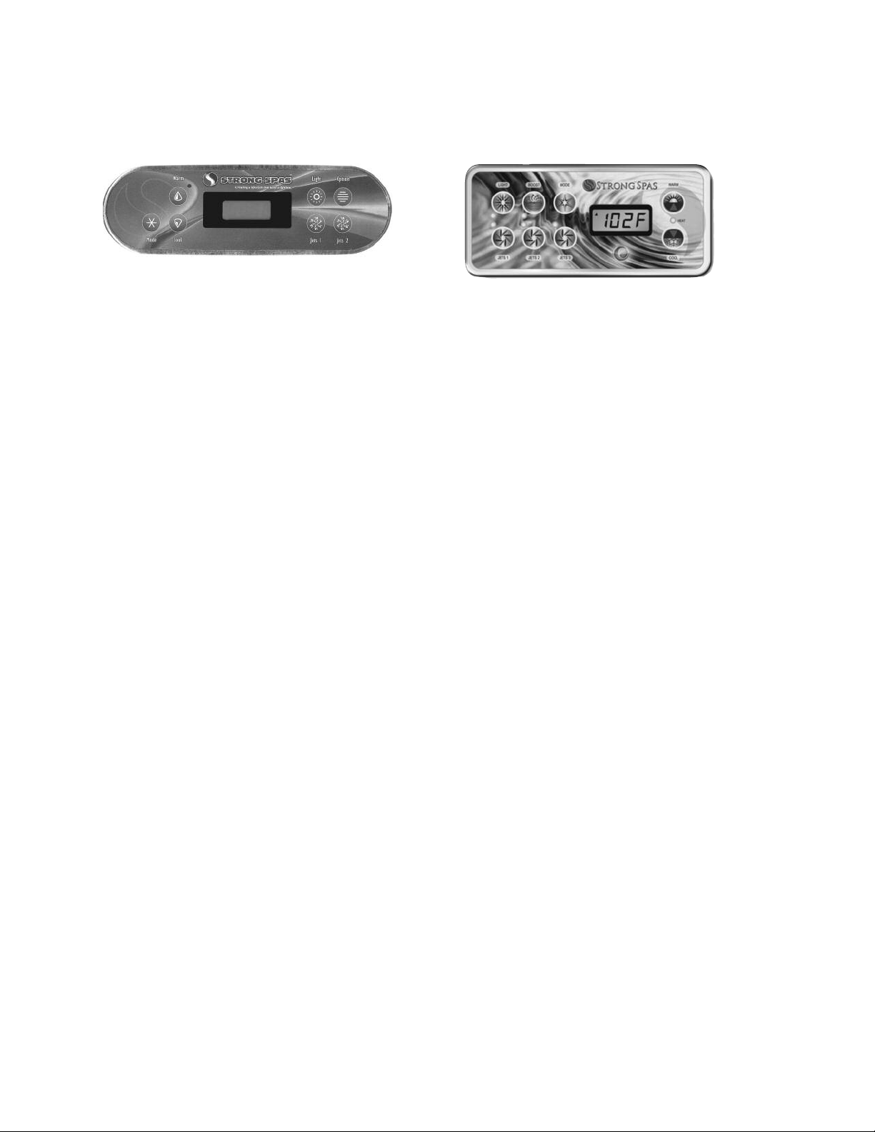
Topside Control Panels
System Settings
When your spa is first actuated, it will go into Prim-
ing mode, indicated by “Pr.” The Priming mode will
last for less than 5 minutes (press a Temperature
button to skip Priming Mode) and then the spa will
begin to take temperature readings, followed by the
heater test cycle. After completed, the heater will
turn on, heat the spa and maintain the water tem-
perature in the Standard mode.
The start-up temperature is set at 100°F/37°C.
The last measured temperature is constantly dis-
played on the LCD. Note that the last measured
spa temperature displayed is current only when the
pump has been running for at least 2 minutes.
Maximum Temperature is set at 104ºF/40ºC
as required by U /CSA.
Minimum temperature is 80ºF/26ºC.
Note: If the spa is current y in a heating or fi tration
cyc e the primary pump wi on y switch between high
and ow. It cannot be turned off unti the heating or fi -
tration cyc e is comp eted.
Preset Filter Cycles
The first filter cycle
begins 6 minutes after
the spa is energized.
The second filter cycle begins 12 hours later. The
default filter time is 2 hours. Recommended setting
is F2.
Ex mple: In 12 hour period (1 cycle), setting of F2
me ns 2 hours of filtr tion on, 10 hours of filtr tion off.
You m y choose F2, F4, F6, F8 or c (continuous).
To program, press the WARM/TEMP button,
immediately followed by JETS/JETS 1. Press WARM/
TEMP button to adjust. Press JETS/JETS 1 to lock in
selection. After locking in a D, N, OR DN may
appear. If so, press WARM/TEMP until DN appears,
and press JETS/JETS 1 to lock in selection.
1. Fading: The lights will cycle through all the
colors in this order: White, Cyan, Magenta, Blue,
Chartreuse, Green, Red
2. Color Locked: This cycle offers a hard color
change without fading.
3. Quick Color Change: Each time you press the
button, you advance to the next color.
4. Flashing white: The LED lights will flash white.
Spa Modes
Standard Mode is programmed to maintain the
desired temperature. Note that the last measured
spa temperature dis-played is current only when the
pump has been running for at least 2 minutes. “ST”
or "STD" will be displayed momentarily when you
switch into Standard Mode. The temperature is
constantly displayed when in Standard Mode. This is
the best mode to use during COLD weather.
(FRQRP\0RGH heats the spa to the set
temperature only during filter cycles or if the
temperature falls to 20 degrees below set
temperature. “EC” or "ECN" will display solid when
temperature is not current, and will alternate with
the temperature, when temperature is current. This
is the best mode to use during WARM weather.
6OHHS0RGHheats the spa to 20 degrees below set
temperature, only during filtration cycles. “SL” will
display solid when temperature is not current, and
will alternate with temperature when temperature
is current, but only within 20 degrees of your set
temperature.
Freeze Protection
If the temperature sensors detect a drop to below
44°F/6.7°C within the heater, the pumps will auto-
matically activate to provide freeze protection. The
equipment stays on until 4 minutes after the sensors
detect that the spa temperature has risen to
45°F/7.2°C or higher.
Lights
Press the ight button on the topside control panel
to turn the spa light on. If your spa has perimeter
LED lights, they will also light up at the same time as
the spa light. LEDs operate in four modes. The mode
is changed by turning the light off and then immedi-
ately back on
Customer Service 1•800•787•6649 17
One-Pump Spas
Jets
Touch the “Jets” button once to turn the main
2-speed pump on or off, and to shift between low
and high speeds. If left running, the low speed of the
pump will automatically turn off after 2 hours, and
the high speed will automatically turn off after 15
minutes.
Warm/Cool
To display the Set Temperature, press either the
“WARM” or “COOL” button once. The LCD will
begin to flash the set temperature. If you want to
increase or decrease the desired temperature, press
the “WARM” or “COOL” button accordingly. Once
at the desired temperature, allow a few seconds for
the flashing to cease. Your Set Temperature has now
been successfully set.
MODE CHANGE
To change the mode on the spa, press WARM
followed by LIGHT.
One-Pump + Blower Spas or
Two-pump (2-speed + 1-speed)
Jets/Jets 1
Touch the “Jets or Jets 1” button to turn the main 2-
speed pump on or off, and to shift between low and
high speeds. If left running, the low speed of the
pump will automatically turn off after 2 hours, and
the high speed will automatically turn off after 15
minutes.
Boost/Jets 2
The “Boost or Jets 2” button will operate the
blower pump, if equipped, or the 1-speed pump.
MODE CHANGE
To change the mode on the spa, press TEMP
followed by LIGHT.
Operate Your Spa
JetV
Press the “Jets 1” button to turn the main 2-speed
pump on or off, and to shift between low and high
speeds. If left running, the low speed of the pump
will automatically turn off after 2 hours, and the high
speed will automatically turn off after 15 minutes.
-HW-HW
Press the “Jet 2/Jet 3” button:
1. Once to turn Pump 2 On / Pump 3 Off
2. Again to turn Pump 2 On / Pump 3 On
3. Again to turn Pump 3 On / Pump 2 Off
4. Again to turn Pumps 2 & 3 Off
Two-Pump + Blower Spas or
Three-pump Spas (4 button topside)
MODE CHANGE
To change the mode on the spa, press TEMP
followed by LIGHT.
“Temp” Button
To display the Set Temperature, press the “TEMP”
button once. The LCD will begin to flash the set
temperature. To change the set temperature press
the “TEMP” button again prior to the flashing timing
out. The temperature will go either up or down. To
change the temperature in the opposite direction
wait for the LCD to stop flashing. Press the “TEMP”
button again to resume the LCD flashing screen, and
then press the “TEMP” button. Once at the desired
temperature, allow a few seconds for the flashing to
cease. Your Set Temperature has now been set.
18
Jets 1
Touch the “Jets 1” button once to turn pump 1 on
or off, and to shift between low and high speeds. If
left running, the low speed of the pump will auto-
matically turn off after 2 hours, and the high speed
will automatically turn off after 15 minutes.
Jets 2
Touch the “Jets 2” button once to turn pump 2 on
or off and to shift between low and high speeds. If
left running, pump 2 will automatically turn off after
15 minutes.
Option/Boost (if equipped)
This button is used to turn on the blower/pump in 3
pump spas. This is 1-speed only and will turn off au-
tomatically after 15 minutes.
Two-Pump Spas, Two-Pump +
Blower Spas, and Three-Pump
+ Blower Spas (6-8 button
rectangle topside)
Jets 1
Press the “Jets 1” button once to turn pump 1 on or
off, and to shift between low and high speeds if
equipped. If left running, the pump will turn off after
a timeout period. The pump 1 low speed timeout on
some systems may be as long as 4 hours.
On non-circ systems, the low speed of pump 1 runs
when the blower or any other pump is on. It may
also activate for at least 1 minute every 30 minutes
to detect the spa temperature (polling) and then to
heat to the set temperature if needed, depending
upon mode. When the low speed turns on automat-
ically, it cannot be deactivated from the panel; how-
ever, the high speed may be started.
Jets 2
Press the “Jets 2” button once to turn pump 2 on or
off. If left running, the pump will turn off after a
timeout period.
Jets 3 (optional on some systems)
Press the “Jets 3” button once to turn pump 3 on or
off. If left running, the pump will turn off after a
timeout period.
Blower/Boost (optional on some systems)
1-speed operation: on/off; If left on, the blower will
automatically turn off after a timeout period.
Warm/Cool
To display the Set Temperature, press either the
“WARM” or “COOL” button once. The LCD will
begin to flash the set temperature. If you want to
increase or decrease the desired temperature, press
the “WARM” or “COOL” button accordingly.
Once at the desired temperature, allow a few
seconds for the flashing to cease. Your Set
Temperature has now been successfully set.
Operate Your Spa
Two-Pump Spas and Two-Pump +
Blower Spas (7 button oval topside)
Warm/Cool
To display the Set Temperature, press either the
“WARM” or “COOL” button once. The LCD will
begin to flash the set temperature. If you want to
increase or decrease the desired temperature, press
the “WARM” or “COOL” button accordingly. Once
at the desired temperature, allow a few seconds for
the flashing to cease. Your Set Temperature has now
been successfully set.
MODE CHANGE
To change the mode on the spa, press WARM
followed by MODE.

Customer Service 1•800•787•6649 19
MODE CHANGE
To change the mode on the spa, first press MODE
to enter mode programming. Press COOL to cycle
through to desired mode (LCD flashes until
confirmed), then press MODE again to confirm
selection.
Standard-In-Economy mode
Pressing JETS 1 while in Economy mode puts the spa
in Standard-In-Economy mode, (“SE”) which
operates the same as Standard Mode, then reverts
to Economy Mode automatically after 1 hour. Dur-
ing this time, pressing “Cool” or “Warm” followed
by “Light” will revert the mode to Economy immedi-
ately.
Standby Mode
Pressing WARM or COOL followed by BLOWER or
JETS 2 will turn off all spa functions temporarily. This
is helpful when changing a filter. Pressing any button
exits Standby mode. On some systems the “Jets 1”
button will control the pump in Standby Mode
(“Drain Mode”). In this case, press any other button
to exit. System will revert to pre-vious mode after 1
hour.
Operational and
Energy Tips
1.Control Valves – air and water
controls on the top of spa
a. Average to Cold Climate - When not in the
spa, make sure the valves are turned off. All these
valves will inject a certain amount of air into the
water which causes a cooling effect. Therefore
your spa will have to heat more often and cost
more money to operate.
b. Hot Climate – Hot tubs are only designed to
heat up and maintain temperature, therefore a
hot climate can actually make a spa over heat. In
these areas, the control valves can be left open all
the time to help cool the spa down.
Operate Your Spa
2.Filter Settings – Time and
Duration
- To set your filter time, simply power your spa on
at desired filter start time. If you power the spa up
at 8:00am, it will filter at 8:00am and 8:00pm daily
until the power is turned off and on again.
- If your electric provider offers different rate per
KWH (peak/off-peak) then you will want your filter
time to take place during off-peak time.
- If you are experiencing over heating with your spa,
have the spa filter run during cooler times of the
day, and leave the control valves opened like
mentioned prior.
- The factory setting is F2, which means the spa will
filter 2 hours for every 12 hour period. 4 hours
total per day. Since we use a large primary pump
for your filtration, it moves a lot of water quickly.
Therefore we recommend you keep your filtration
at no more than F4, anything longer will just waste
electricity and in warm climates the spa may
overheat.
3.Heating Modes – Standard,
Economy, and Sleep
-4 Button Controllers Only - These options
are not always unlocked from the factory, and
may require a settings change. Attempt to change
the mode several times prior and if no results a
dip switch will need changed.
Standard is the default setting, and you are in
standard mode if none of the other setting codes
show up
- Temperature will be at or near desired tem-
perature constantly.
- Pumps turn on at regular intervals to check and
maintain temperature.
- Best to use at startup of spa, it will heat until
desired temperature is reached.
- Best to use in cold climates.
- Most costly to operate.
20
Operate Your Spa
4.Steam Loss/Venting Around Spa
Cover
- It is normal to see an occasional burst of steam
from around the cover due to pressure releasing
from a high to low area. However heat loss can
be greatly impacted by use of the spa
- Control valves should be turned off when getting
out of the spa in a cool climate.
- Air injects from the cabinet and enters into the
water area. That air not only will cool the cabinet
area, but will also greatly in-crease the pressure
under the cover and cause more steam to release.
- Surfaces are different for all spas, and cov-ers
may provide a better seal is spun differently.
- If the folding seam goes over the controller area,
often more steam will be able to es-cape. Try to
position the cover so that the fold seam goes over
the wider top surface areas on the adjacent sides.
Proper Spa Cover Use
Import nt! Keep the sp covered when not in use!
- Covered spas will use less electricity in maintaining
your set temperature.
- Covering your spa will protect your spa’s finish from
the sun’s ultraviolet rays.
- You are required to keep the spa covered to main-tain
warranty coverage.
- Covering your spa helps prevent children from
drowning in the spa. See the photo for instructions on
mounting the locks and how to lock and unlock the
cover.
- In addition, while a soft spa cover is rigid, it is not
designed to support any weight. Therefore, as a safety
precaution and to preserve the life of your cover, you
must not sit, stand, or lie on it, nor should you place
objects of any kind on top of it.
Economy is the power saving alternative for
regular heating, you will know that you are in
economy by the code displayed. If the pump is
running the current temperature and code will
alternate on the display.
- Spa will only heat during filter period
- Temperature will remain close to desired, but it
will drop between filter periods
- If users can get in a routine, filter period should
overlap the usage time by a half hour. This will
have spa temperature closest to the desired
temperature.
- Example, if using the spa at 8:00 have spa filter
from 6:30 – 8:30.
- Best used in mild to warm climates
- Tests show a 20% reduction in energy con-
sumption when compared to standard mode
Sleep is considered a vacation heater setting,
and will maintain your spa water at the most
affordable price.
- Spa will only heat during your filter period.
- The water temperature may drop up to 20
degrees below your desired temperature.
- Will work in all climates, and will not allow the
spa to freeze.
- Tests show a 50%+ reduction in energy
consumption when compared to standard mode.
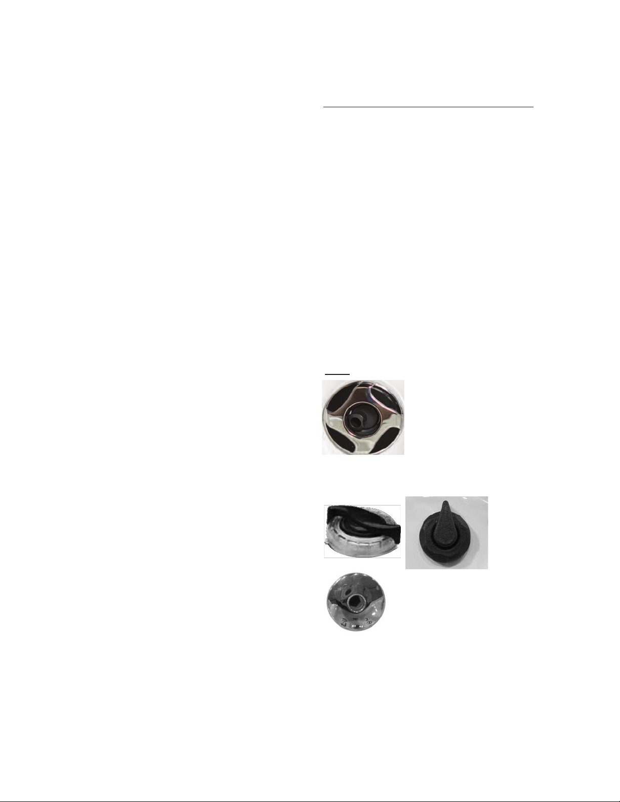
Personal Settings
Jets
Most jets in your spa are ad-
justable. Rotating the face of an
adjustable jet to the left
(counter-clockwise) will increase
the amount of water flow
through the jet. Rotating the face
of an adjustable jet to the right (clockwise) will de-
crease the amount of water flow through the jet.
Neck jets can
be turned on
and off using
the nearby
water on/off
knob.
Blower jets are not adjustable,
but can be turned on and off using
the Aux or Option button on
your Control Panel.
This manual suits for next models
71
Table of contents
Popular Hot Tub manuals by other brands


InnovaSpa
InnovaSpa 110-16 owner's manual

BullFrog
BullFrog 2000 owner's manual

Dynasty Spas
Dynasty Spas MC-MP-DY4 Quick reference card

Poolspa
Poolspa SPA Marina Installation and user manual

Aquatic
Aquatic HOTSOAK 72 AI12AIR7240HS Specification sheet

Sterling Plumbing
Sterling Plumbing ENSEMBLE 76111120 Specifications