eWBM eLR100-UL-EB User manual
eLR100-UL-EB
Manual
eLR100-UL-EB
Powered by MS500

Contetns
eLR100-UL-EB Manual for Consumer Products, Rev. 0.1, 03/2019 2 | 19
CONTETNS
Contetns.............................................................................................................................................................................................. 2
1. Introduction............................................................................................................................................................................ 5
1.1. Features.............................................................................................................................................................................. 5
1.2. Block Diagram .................................................................................................................................................................... 6
2. System Description................................................................................................................................................................. 7
2.1. Part Description.................................................................................................................................................................. 7
2.2. Power ................................................................................................................................................................................. 8
2.3. Reset................................................................................................................................................................................... 9
2.4. Boot.................................................................................................................................................................................. 10
2.5. UART................................................................................................................................................................................. 11
2.6. Optional Part .................................................................................................................................................................... 13
3. Application Note................................................................................................................................................................... 16
3.1. Firmware Update ............................................................................................................................................................. 16
Document Revision and Reference................................................................................................................................................... 18

Contetns
eLR100-UL-EB Manual for Consumer Products, Rev. 0.1, 03/2019 3 | 19

Contetns
eLR100-UL-EB Manual for Consumer Products, Rev. 0.1, 03/2019 4 | 19

Introduction
eLR100-UL-EB Manual for Consumer Products, Rev. 0.1, 03/2019 5 | 19
1. INTRODUCTION
eLR100-EVB 은LoRa Module eLR100-UL-00 을이용한 개발을 쉽게 하기 위해 제작된 Evaluation Board 입니다.
1.1. FEATURES
⚫eLR100-US/HF Module include
-eWBM ultra low power advanced security MCU MS500
✓Cortex M0
✓Hardware Security system.
-Semtech SX1272 radio transceiver supporting LoRa.
-UART Communication Interface
✓AT-Command set support for LoRaWAN
⚫SMA connector

Block Diagram
eLR100-UL-EB Manual for Consumer Products, Rev. 0.1, 03/2019 6 | 19
1.2. BLOCK DIAGRAM
Figure 1 Hardware Block Diagram
System Description
eLR100-UL-EB Manual for Consumer Products, Rev. 0.1, 03/2019 7 | 19
2. SYSTEM DESCRIPTION
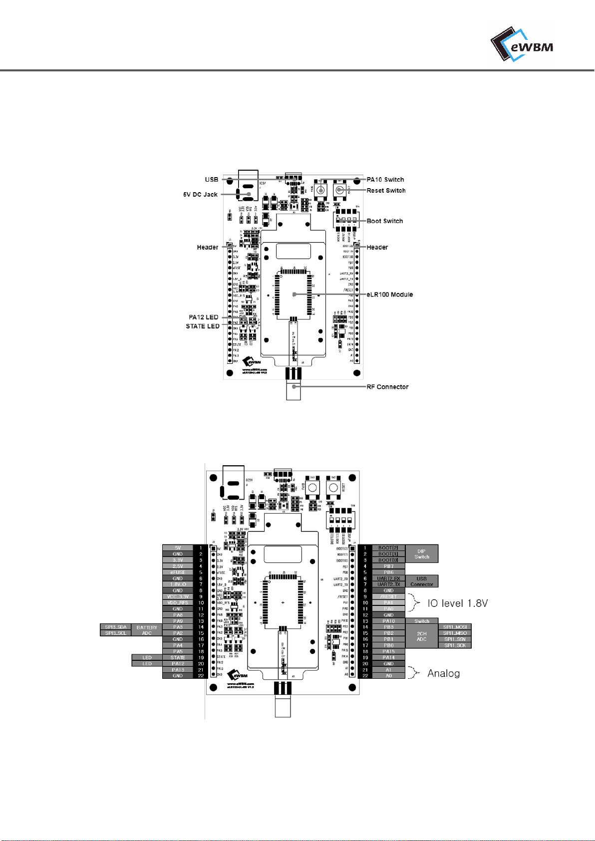
2.1. PART DESCRIPTION
Figure 2 eLR100-UL-EB Parts
Figure 3 eLR100-EB Header J3,4 pinout diagram
System Description
eLR100-UL-EB Manual for Consumer Products, Rev. 0.1, 03/2019 8 | 19
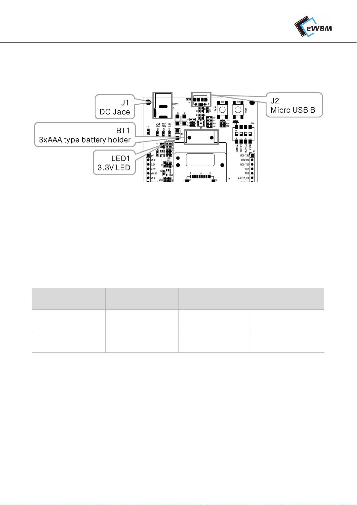
2.2. POWER
Figure 4 Input Power, Power LED
2.2.1. Input Power
전원은 Battery(BT1), DC Jack(J1), USB Connector(J2)를통해서 입력된다.
Table 1. Input Power
Input
Battery
DC Jack
USB Connector
Reference
BT1
J1
J2
Connector
AAA 3EA Holder
DC 5V 2.0 pi
Micro USB B Type
2.2.2. Power LED (LED1)
입력전원을 통해 전원을 입력 받고, Board 회로를 통해 3.3V 전원이 생성이 되면 LED 가ON 됩니다.

System Description
eLR100-UL-EB Manual for Consumer Products, Rev. 0.1, 03/2019 9 | 19
2.3. RESET
Figure 5 Reset Header, Switch
2.3.1. Reset Switch (SW2), Reset Header (J4.9)
⚫RESET 의IO Level 은1.8V 입니다.
⚫Module 내부에 1.8V Pull UP 회로가 구성되어 있습니다
⚫Host Board 제어시에는 기본값은 Input 으로 설정하며, Reset 시에는 High 를1ms 유지 후에
기본값 Input 으로 설정합니다.
Example Code
pinMode(8 ,INPUT);
pinMode(8 ,OUTPUT);
digitalWrite(8, LOW);
delay(1);
pinMode(8 ,INPUT);
2.3.2. Software Reset (AT Command)
AT+Command ‘AT+RESET’ 를이용해서 Reset 이가능합니다.
자세한 내용은 AT+Command_Manual 을참고합니다

System Description
eLR100-UL-EB Manual for Consumer Products, Rev. 0.1, 03/2019 10 | 19
2.4.BOOT
2.4.1. Boot Mode / eFuse
Boot Mode/eFuse Setting Switch (SW4)를통해서 Boot Mode, eFuse 설정이 가능합니다.
Figure 6 Boot Mode Setting
Table 2. Boot Mode Table
BOOT MODE
BOOT[2]
BOOT[1]
BOOT[0]
eFUSE
ROM BOOT
(Default)
OFF
0
OFF
0
OFF
0
OFF
0
UART-Flash Update
(Firmware Update)
OFF
0
ON
1
OFF
0
OFF
0
eFUSE Data Mode
OFF
0
OFF
0
ON
1
ON
1
2.4.2. STATE LED (LED 2)
LoRa Module 이정상적으로 Booting 이된다면 LED2 가점등됩니다.
System Description
eLR100-UL-EB Manual for Consumer Products, Rev. 0.1, 03/2019 11 | 19
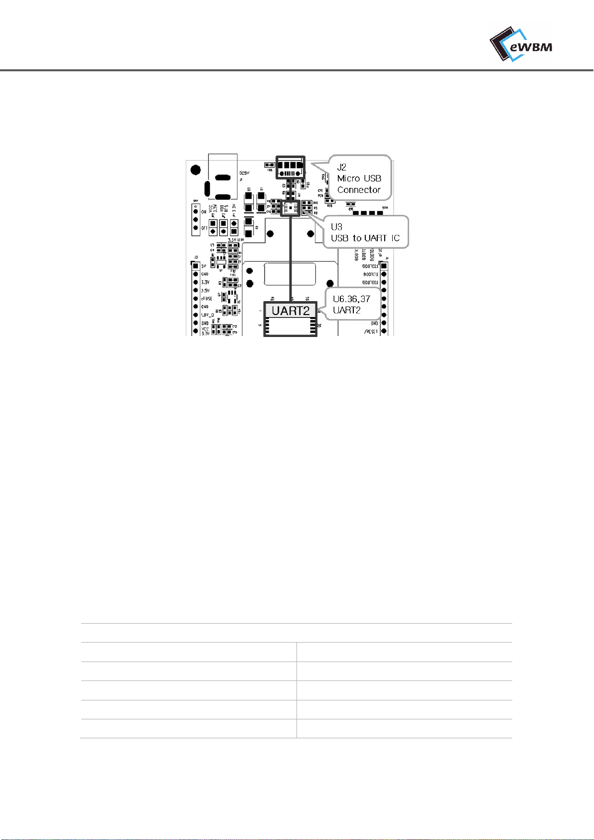
2.5. UART
Figure 7 Arduino Type Header Description
2.5.1. UART 2
LoRa Module (eLR100-US/UL) 제품의 UART2 를USB Connector(J2)를통해서 통신이 가능합니다.
Firmware Update, AT+Command 기능이 가능합니다.
AT Command Setting
⚫Boot Mode Setting
-ROM Boot Mode (BOOT [2:0] = 3'b000)
⚫Serial Port Setup
Port Setup Information
Baud Rate
115200
Data
8 bit
Parity
None
Stop
1 bit
Flow Control
None

System Description
eLR100-UL-EB Manual for Consumer Products, Rev. 0.1, 03/2019 12 | 19
Firmware Update Mode Setting
⚫Boot Mode Setting
-UART-Flash Update Mode (BOOT [2:0] = 3'b010)
⚫Serial Port Setup
-Firmware Updater Setting 참고
System Description
eLR100-UL-EB Manual for Consumer Products, Rev. 0.1, 03/2019 13 | 19
2.6. OPTIONAL PART
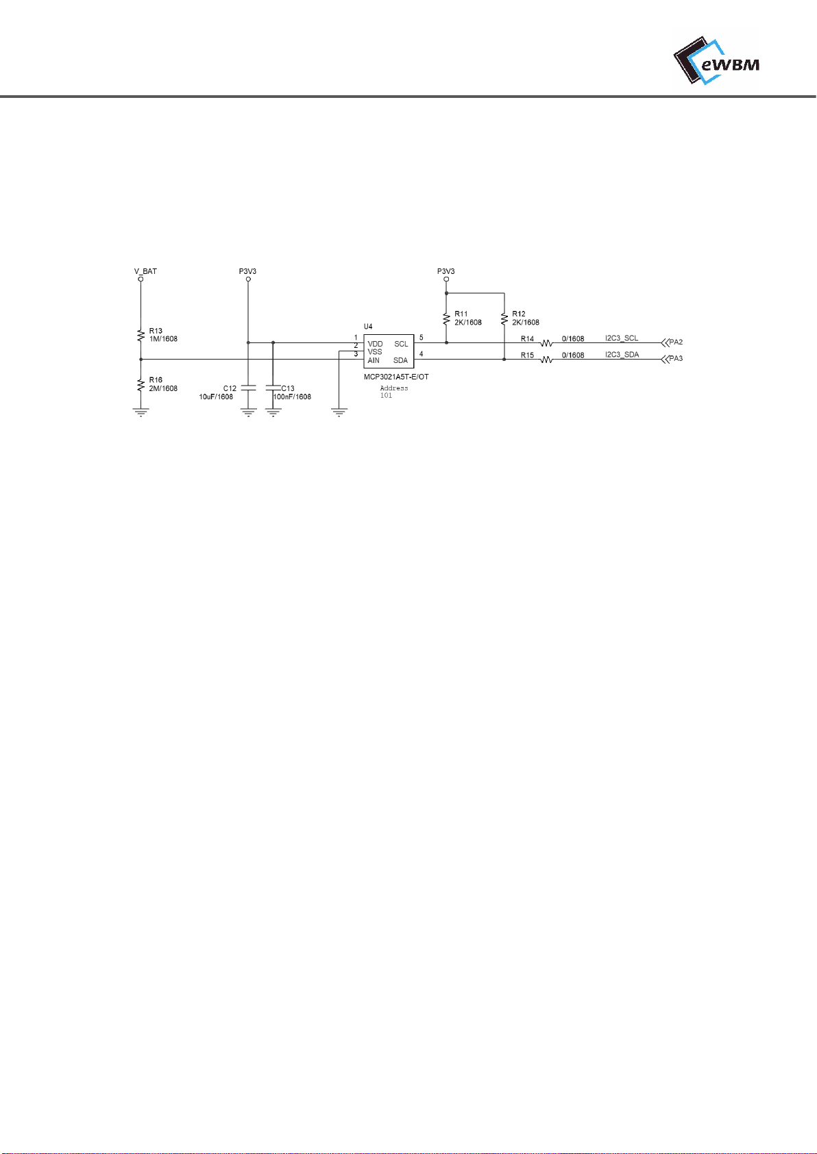
2.6.1. Battery Check
입력전원을 Battery 로사용하는 경우 Battery 의전압을 측정할 수있습니다.
Figure 8 Battery Supply Circuit
⚫V_BAT 최대 입력전압: 4.9V
⚫ADC Converter Chip: MCP3021A5T-E/OT
-Interface: I2C3(PA2,3)
✓400kHz Fast Mode
-Resolution: 10-bit
-Standby Current:5 nA typical, 1 µA maximum
-Address: 101

System Description
eLR100-UL-EB Manual for Consumer Products, Rev. 0.1, 03/2019 14 | 19
2.6.2. ADC
LoRa Module 의SPI 을이용하여 2 채널(A0, A1)의ADC 를사용할 수있습니다.
⚫Dual Channel ADC Converter Chip
-Interface: SPI1(PB0,1,2,3)
✓1MHz Less
-Resolution: 10-bit
-Standby Current:5 nA typical, 2 µA maximum
⚫Analog Input Channel Locations
-A0: J4.22
-A1: J4.21
Figure 9 ADC Circuit

System Description
eLR100-UL-EB Manual for Consumer Products, Rev. 0.1, 03/2019 15 | 19
2.6.3. GPIO
LoRa Module 의설정으로 사용하지 않는 GPIO 를제어가 가능합니다.
Command “AT+GPIO”를이용하여 In/Output 설정, 상태확인이 가능합니다.
자세한 내용은 AT+Command Manual 을참고합니다.
LED (LED3)
LoRa Module 의PA12 를이용하여 LED(LED3)제어가 가능합니다.
PA12 가OUTPUT HIGH 인경우에 점등이 됩니다.
Switch (SW3)
SW3 를통하여서 LoRa Module 의PA10 의입력상태를 제어할 수있습니다.
PA10 은HIGH(3.3V)가기본이며, SW3 를누르면 LOW(0V)가됩니다.

Application Note
eLR100-UL-EB Manual for Consumer Products, Rev. 0.1, 03/2019 16 | 19
3. APPLICATION NOTE
3.1. FIRMWARE UPDATE
3.1.1. Board Setting
Figure 10 Firmware Update Board Setting
1. Boot Mode Switch(SW4) 를이용하여 Firmware Upload Mode 로설정합니다.
Table 3. Boot Mode Setting
2. Micro USB Connector(J2)와PC 를Micro USB Cable 로연결합니다.
3. Reset Switch (SW2)를눌러서 Reset 을합니다.
Mode
Switch Setting
Description
Default Mode
(ROM BOOT)
0000
동작 기본 Mode
Firmware Upload Mode
(UART to Flash Boot)
0100
Firmware Update 시에 사용
Update 후에는 Default Mode 전환
Application Note
eLR100-UL-EB Manual for Consumer Products, Rev. 0.1, 03/2019 17 | 19
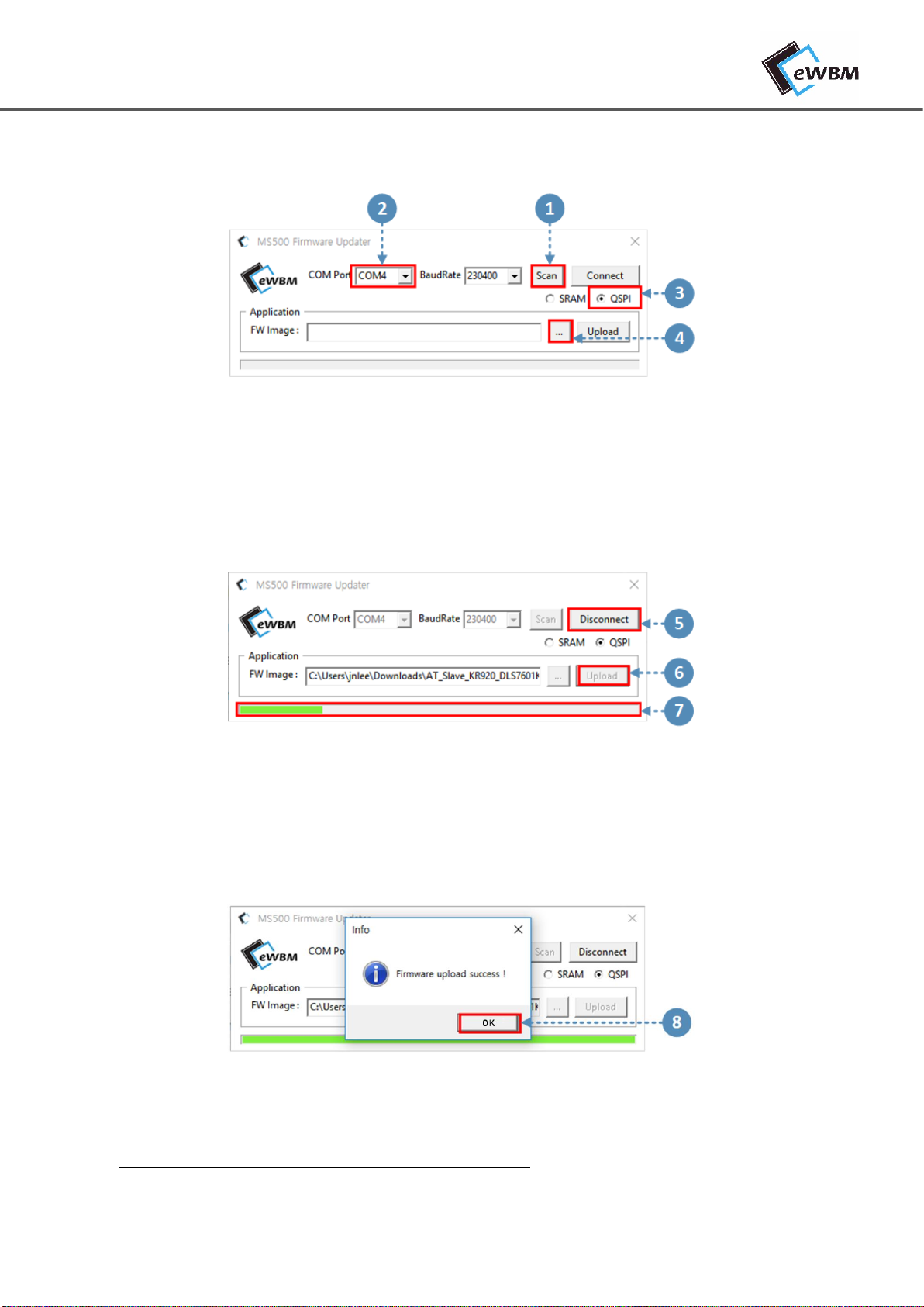
3.1.2. Firmware Updater Setting & Upload
Figure 11 Firmware Setting 1
1. AS-BELLNAVY-LRWAN-04K41 가PC 와연결된 상태에서 Scan 을클릭합니다.
2. COM Port 를AS-BELLNAVY-LRWAN-04K41 와연결된 Port 로설정합니다.
3. QSPI 를선택합니다.
4. …을클릭해서 Upload 할.img 파일을 선택합니다.
Figure 12 Firmware Setting 2
5. Connect 를클릭합니다.
6. Upload 를클릭합니다.
7. 녹색 Bar 를통해 Upload 상태를 확인합니다.
Figure 13 Firmware Setting 3
⚫“Firmware Upload Success !” 메시지를 확인 후클릭합니다.
Upload 후에는 Board 설정을 기본값으로 되돌립니다.

Document Revision and Reference
eLR100-UL-EB Manual for Consumer Products, Rev. 0.1, 03/2019 18 | 19
DOCUMENT REVISION AND REFERENCE
Revision History
Revision
Date
Description
0.1
2019-03-05
1st Release

Copyright - © 2019 eWBM Co., Ltd. All rights reserved 19 | 19
COPYRIGHT NOTICE
Copyright © 2019 eWBM Co., Ltd. All rights reserved.
This document is the copyrighted work of eWBM Co., Ltd. and is owned by eWBM Co., Ltd. It is provided as a
reference for the sole purpose of MS500 microcontroller based system design.
No part of the software and documentation may be reproduced, transmitted, or translated, in any form or by
any means, electronic, mechanical, manual, optical, or otherwise, without prior written permission of eWBM
Co., Ltd.
NO WARRANTY NOTICE
eWBM Co., Ltd. makes no warranty of any kind in regard to this material which is delivered to you as is,
including, but not limited to, the implied warranties as to its accuracy or fitness for a specific purpose. Any use of
this technical documentation or the information contained therein is at the risk of the user. eWBM Co., Ltd. shall
not be liable for errors contained therein or for incidental consequential damages in connection with the
furnishing, performance or use of the material.
Other manuals for eLR100-UL-EB
1
Table of contents


