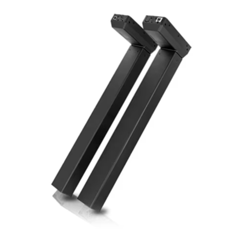
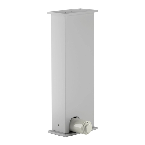
Ewellix CPSM User manual

Feature 1
max 2 lines
Feature 3
Feature 4
Feature 2
max 2 lines
INSTALLATION, OPERATION AND
MAINTENANCE MANUAL
CPSM
Servo pillar


33
Contents
1.0 General information......................................................4
1.1 Information in this manual ...............................................4
1.2 Explanation of symbols and signal words ......................4
1.3 Limitation of liability ........................................................5
1.4 Copyright.........................................................................5
1.5 Spare parts......................................................................5
1.6 Warranty terms................................................................5
1.7 Customer service ............................................................5
2.0 Safety .............................................................................6
2.1 Use ...................................................................................6
2.2 Responsibility of the owner and processor....................7
2.3 Personnel requirements..................................................7
2.4 Specic dangers .............................................................8
2.5 Safety equipment............................................................8
2.6 Safeguard against restart ...............................................8
2.7 Modications of device ...................................................8
3.0 Technical data ..............................................................9
3.1 Ambient conditions .........................................................9
3.2 Product label...................................................................9
4.0 Structure and function .............................................. 10
4.1 Overview ....................................................................... 10
4.2 Brief description............................................................ 11
4.3 Special features ........................................................... 12
4.4 Requirements for motor, control unit and power supply 12
4.5 Connections.................................................................. 13
4.6 Operating elements....................................................... 13
4.7 Options ......................................................................... 13
5.0 Transport, packaging and storage .......................... 14
5.1 Delivery inspection........................................................ 14
5.2 Return to the manufacturer........................................... 14
5.3 Packaging...................................................................... 14
5.4 Storage.......................................................................... 15
6.0 Installation and rst operation ................................ 16
6.1 Installation location ....................................................... 16
6.2 Inspections prior to initial operation............................. 16
6.3 Installation..................................................................... 17
6.4 Connection to the control unit ......................................20
6.5 Connection to power supply.........................................20
6.6 Initial start-up ................................................................20
7.0 Operation ....................................................................21
7.1 Safety ............................................................................. 21
7.2 Turn on........................................................................... 21
7.3 Turn o........................................................................... 21
7.4 Actions before use......................................................... 21
7.5 Actions during the operation ........................................22
7.6 Emergency disengagement ..........................................22
8.0 Maintenance ...............................................................23
8.1 Maintenance plan .........................................................23
8.2 Maintenance work.........................................................23
8.3 Measures following completed maintenance............... 24
9.0 Malfunctions ...............................................................25
9.1 Malfunction table ..........................................................26
9.2 Start of operation after .................................................26
10.0 Dismantling ..............................................................27
10.1 Dismantling ..................................................................27
10.2 Disposal.......................................................................27
11.0 Appendix ..................................................................28
11.1 Technical data ............................................................28
11.2 Plans and diagrams.....................................................29
WARNING
Read this manual before installing,
operating or maintaining this actuator.
Failure to follow safety precautions and
instructions could cause actuator failure
and result in serious injury, death or
property damage.

4
CPSM
1.0 General information
1.1 Information in this
manual
This manual provides important information on how to work
with the actuator (also called the device) safely and e-
ciently. The Manual is part of the device, must always be
kept and should be available for personnel to read at any
time. All personnel working with the device must read and
understand this manual before starting any work. Strict
compliance with all specied safety notes and instructions is
a basic requirement for safety at work.
Moreover, the accident prevention guidelines and general
safety regulations applicable at the place of use of the de-
vice must also be complied with.
For better representation of circumstances, the illustrations
in this manual are not necessarily to scale and may vary
from the actual design of the device.
All information and notes in this manual were compiled with
due consideration given to applicable standards and regula-
tions, the present status of technology and our years of
knowledge and experience.
1.2 Explanation of symbols
and signal words
Safety precautions
Safety precautions are identied by symbols and signal
words dened on the right hand side of this page. These sig-
nal words indicate the severity of the hazard.
Adhere to these safety precautions and take caution in order
to avoid accidents that may result in personal injuries or
damage to property
NOTE
Emphasizes useful hints and
recommendations as well as information
for ecient and trouble-free operation.
NOTICE
Indicates a dangerous situation, which
can lead to minor or moderate property
damage, if the precautionary measures
are ignored.
CAUTION
Indicates a dangerous situation, which
can lead to minor or moderate injury, if
the precautionary measures are ignored.
WARNING
Indicates a dangerous situation, which
can lead to serious personal injury or
death, if the precautionary measures are
ignored.
DANGER
Indicates a dangerous situation, which
will lead to death or serious personal
injury, if the precautionary measures are
ignored.

5
1.0 General information
1.3 Limitation of liability
All information and notes in this manual were compiled un-
der due consideration of valid standards and regulations,
the present status of technology and our years of
knowledge and experience.
The manufacturer will not be liable for damage resulting
from:
• Disregarding this manual
• Unintended use
• Employment of untrained personnel
• Unauthorized conversions
• Technical modication
• Manipulation or removal of the screws on the device
Where the device has been customized, the actual product
delivered may be dierent from what is described in this
manual. In this case, ask Ewellix for any additional instruc-
tions or safety precautions relevant to these actuators.
We reserve the right to make technical modications to the
actuator to improve usability
1.3.1 Validity
The instructions in this manual refer to the telescopic pillar
CPSM with the following identication:
• Manufacturer: Ewellix
• Product name: Telescopic pillar CPSM
• Type designation: CPSM10–BN–10–abbbb–cdd–ee–f
• Year of manufacture: start from 2018
Where the device has been customized by Ewellix, the ac-
tual product delivered may be dierent from what is de-
scribed in the manual. In this case, ask Ewellix for any addi-
tional instructions or safety precautions relevant to these.
We reserve the right to make technical modications to the
device units to improve usability.
1.4 Copyright
This manual is protected by copyright law and to be used
exclusively by Ewellix customers internal purpose
Passing this manual on to third parties, duplication of any
kind – even in the form of excerpts – as well as the use and/
or disclosure of the contents without the written consent of
the manufacturer is not permitted, except for internal
purposes.
Violation of Ewellix’s copyright may become the subject of a
future claim for damages.
1.5 Spare parts
This actuator is not designed for repair work. All warranty
and service claims become void without notice if any screws
on the linear actuator have been manipulated.
WARNING
Safety hazard caused by use of non-genuine spare parts
Wrong or faulty spare parts can adversely aect safety and
cause serious injury, damage, malfunction or total failure.
Therefore:
• Spare parts in/on the device may only be replaced by the manu-
facturer.
If the device cannot be repaired on site by authorized per-
sonnel it must be dismantled and sent to the manufacturer.
1.6 Warranty terms
The applicable and eective warranty terms are those con-
tained in the manufacturer’s terms and conditions of sale
contained in the Ewellix sales contract that governs this
sale.
1.7 Customer service
Ewellix Customer Service is always available to provide
technical information and to answer questions.
The contact information for Ewellix Customer Service can be
found on www.ewellix.com.

6
CPSM
6
2.0 Safety
2.1.2 Product life time
The product life time of the telescopic pillar CPSM depends
on the stroke, the load and the cycle of the application.
Please ask the manufacturer to calculate and provide the
L10 lifetime of the telescopic pillar CPSM for the specic ap-
plication case.
2.1.3 Unintended use
Any use other than the intended use, or modications to the
device without the manufacturer’s written agreement, or op-
eration beyond the technical limits, is considered
unauthorized.
NOTE
Any unauthorized use of the device can cause personal injury
and property damage. Always adhere to the instructions given in
this manual.
2.1 Use
This section provides an overview of important safety as-
pects of installing, operating and maintaining this device.
Disregarding this manual and safety regulations specied
therein may result in considerable danger and possible seri-
ous injury or death or damage to device or equipment.
WARNING
Risk from misuse
Any utilization of this device beyond its intended purpose may
lead to potentially hazardous situations.
Therefore:
• Strictly adhere to all safety precautions and instructions in this
operating manual.
• Do not allow this device to be subjected to weather conditions,
strong UV rays, corrosive or explosive air media as well as other
aggressive media.
• Do not modify, retool or change the structural design or individual
components of the linear module.
• Never use the device outside of the technical application and op-
erational limits described in this manual.
2.1.1 CPSM pillar intended use
The telescopic pillar CPSM has been designed and built to
be operated in accordance with its intended use.
• The telescopic pillar CPSM is designed to lift dynamically
centric and/or o–centric loads in vertical direction.
• The telescopic pillar CPSM is designed to be used for
continuous operation at high speed
• Note: The performance is dependent on the motor selec-
tion. The limiting values must not be exceeded.
(⮑ 4.4 Requirements for motor, control unit and
power supply, page 12)
• The telescopic pillar CPSM is designed for height adjust-
ments of applications in the industrial segment. Any other
use of this device must be authorized by the manufacturer.
• The telescopic pillar CPSM is only suitable for indoor ap-
plications and may not be exposed to the outdoors, heavy
UV radiation or dusty, corrosive or explosive environ-
ments.
If you use the telescopic pillar CPSM for any use other than
that cited, the manufacturer cannot be held responsible for
any resulting damage or injury.

7
2.0 Safety
7
2.2 Responsibility of the
owner and processor
The device is designed for commercial applications by its
owner or processor.
The processor is the contracting partner of the reseller or
the manufacturer.
The processor installs the device in a complete system
(application).
The owner or processor of the system is therefore subject to
the requirements of the Occupational Health and Safety Act.
In addition to the safety instructions in this manual, the
owner or processor must do the following concerning these
safety and accident prevention guidelines and environmental
protection regulations applicable to the site of the system’s
installation:
Inform themselves of applicable industrial safety regulations.
They must also determine additional hazards that arise due
to the specic working conditions prevailing at the site
where the device is installed using risk assessment. The risk
assessment must be implemented in the form of work in-
structions for device operation.
• Conrm that the work instructions created for the system,
including the device satisfy current legal requirements and
must alter the instructions accordingly.
• Clearly regulate and specify the responsibilities for installa-
tion, operation, maintenance, and cleaning.
• Ensure that all employees who deal with the device have
read and understood this manual.
• Provide personnel with the required protective equipment.
• Provide training for personnel at regular intervals and in-
form personnel of the hazards.
In addition, the owner or processors must ensure that the
device is in adequate working condition. They must do the
following:
• Ensure that the maintenance intervals described in these
instructions are complied with.
• Have all safety devices inspected regularly for function and
completeness.
2.3 Personnel
requirements
WARNING
Improper installation, operation and maintenance can result
in serious injury, death or property damage.
Use only qualied, trained personnel (as described below)
who have read, understand and follow these instructions.
2.3.1 Qualications
The following qualications are specied for dierent areas
of activity listed in this manual:
• A trained person (Operator)
Instructed by the customer in an orientation session on the
assigned tasks and possible dangers arising from in case
of improper behavior.
• Qualied personnel
Based on their professional training, know–how and expe-
rience as well as knowledge of the applicable standards
and regulations are able to independently perform as-
signed work activities and to detect and avoid possible
dangers.
• Professional electrician
Based on their professional training, know–how and expe-
rience as well as knowledge of the applicable standards
and regulations are able to independently perform work on
electrical systems and to detect and avoid possible dan-
gers. In addition, the professional electrician has been
trained for the special location where they work and know
the relevant standards and regulations.
Only persons who can be expected to perform their tasks
reliably are permitted as personnel. Persons whose reaction
capabilities are impaired, e.g. through the use of drugs, al-
cohol or medication for example, are not permitted.

8
CPSM
2.4 Specic dangers
The following section lists the residual risks that have been
determined by a risk assessment.
The manufacturer has constructively, and with protective
measures, minimized the eects of existing hazards. Pay at-
tention to the residual hazards and potential countermeas-
ures described and the warnings in the following chapters.
WARNING
Risk of injury from moving parts
Moving parts may cause serious injuries.
Therefore:
• Do not reach into moving parts or touch moving parts during op-
eration.
WARNING
• The end user has to ensure that the motor/signal cables are prop-
erly secured and strain–relieved.
• The control unit is provided by the end user and is not part of the
scope of delivery from Ewellix.
• The telescopic pillar CPSM may be damaged if liquids penetrate
inside the pillar. Keep liquids away!
• The end user has to ensure that an emergency switch is installed
in the application to stop in case of emergency any motion of the
telescopic pillar CPSM immediately.
• The end user has to ensure that a person or an object can be re-
leased in any case of emergency; i.e. the operation of the tele-
scopic pillar CPSM must be guaranteed in case of power loss
with appropriate means.
• The end user must prevent any unintended motion of the tele-
scopic pillar CPSM in their application.
• The motor and signal cables must be laid and xed in a clean and
safe way to prevent them from any damage during operation
2.5 Safety equipment
WARNING
Danger due to malfunctions safety equipment
For safe operation, be sure all features are in good working
order.
Therefore:
• Always check funtionality of safety equipment according to the
maintenance plan.
• Never disengage safety equipment.
• Safety equipment may never be bypassed or modied.
Integration of an emergency-stop system
required (for certain applications)
The device is only intended for installation into an applica-
tion or system. It does not have its own operating control el-
ements
and does not have its own emergency–stop–function.
Install the device so that it is part of an emergency shut–o
system and can be stopped if necessary.
The emergency shut–o system has to be connected in such
a way that a disruption of the power supply or the reactiva-
tion of the power supply after a power disruption cannot
cause a hazardous situation for persons and objects.
The emergency shut–o system must always be easily ac-
cessible.
NOTE
The processor must decide which applications require the
installation of an emergency shut–o system.
2.6 Safeguard against
restart
WARNING
Life–threatening situation through unauthorized restart!
For work in hazard zones, there is a risk that the power supply
will be turned on without prior authorization. This present a life–
threatening situation for people in the hazard zone.
Therefore:
• Follow the information concerning safeguarding against restarting
of the power supply in the chapters of this operating manual.
• Always follow the process to safeguard against a restart as de-
scribed below.
2.7 Modications of
device
WARNING
To avoid hazardous situations and to ensure optimal
performance, do not make any changes or modications to the
device unless they have been specically authorized by Ewellix.
2.7.1 Warning labels
The symbol below can be found on the motor or power supply
near the hot surface.
Hot surfaces can cause burns and should not be touched.
Protection must be provided against accidental contact if
necessary.
WARNING
Danger because of illegible symbols
Over the course of time stickers and decals may become dirty or
illegible for some others reason.
Therefore:
• Keep any safety, warning and operation related decals in legible
condition at all times
• Replace damaged decals or stickers immediately

9
3.0 Technical data
9
3.0 Technical data
The technical data of the telescopic pillar CPSM can be
found in the Appendix.
(⮑ 11.0 Technical data, page 28).
3.1 Ambient conditions
• Temperature range: +10 to +40 °C
• Atmospheric humidity: 5% to 85%
• Non-condensing
• Atmospheric pressure: 700 to 1060 hPa
The telescopic pillar CPSM is suitable for indoor use only
and must not be exposed to weathering, strong UV radiation
or corrosive or explosive atmospheric media.
3.2 Product label
The Product label provides the following information
1. Type designation
2. Centric load
3. Gear Ratio
4. Stroke
5. Serial number
6. Manufacturer-specic company name
7. Manufacturer-specic barcode and address
8. Date of manufacture (month/year)
9. Disposal
1
7 8 9
2 3 4 5 6

10
CPSM
This chapter is intended for all users of telescopic pillar
CPSM and describes the basic design and function of the
device.
4.1 Overview
4.0 Structure and function
1. Customized top plate
2. Optional damping system
3. Backlash-free long lasting guiding pads
4. 2 or 3 section extruded aluminum guiding tubes
5. High eciency ball screw
6. Preloaded bearing arrangement
7. Low friction worm gear reduction
8. Optional electromechanical brake
9. Standard or customized motor interface
10. Motor (Brushless DC or servo AC)
11. Customized bottom plate
1
2
3
4
5
6
8
10
9
11
7

11
4.0 Structure and function
4.2 Brief description
A description of its function enables better understanding of
what the telescopic pillar CPSM and their individual parts do.
4.2.1 Functional principles
The functional principle of the telescopic pillar CPSM is
based on a pushing force for the lifting of centric as well
o-centric loads.
A ange mounted motor (preferably a Brushless DC Motor or
a Servo Motor) (1) drives a ball screw (2) via a coupling (3)
and a worm gear (4). The ball screw is supported in the gear
housing (5) with a taper bearing (6) and is rotating accord-
ingly, the complete drive unit its mounted to the bottom
plate (7). A ball screw nut (8), which is attached to the push
tube (9), moves up and down on the ball screw. The push
tube is mounted to the top plate (10). Optionally a shock ab-
sorber (11) (damping element) can be mounted between the
push tube and the top plate. The telescopic tubes (12) ex-
tend and retract depending on the rotational direction of the
motor. The motor in combination with the control acceler-
ates/decelerates the movement or holds the tube position at
a standstill. The telescopic pillar CPSM design oers to
mount an electromechanical holding brake (13) on the motor
shaft (14).
Motor / control unit
The telescopic pillar CPSM is designed to mount a wide
range of motor options and brands. This feature allows the
customer to choose their preferred motor and controller
equipment. The standard interface of the telescopic pillar
CPSM can be equipped with a customized motor adapter to
ensure the correct t.
(⮑ 4.4 Requirements for motor, control unit and power
supply, page 12).
NOTE
Ewellix is not responsible for the setup of the motor/control unit.
End position
The telescopic pillar CPSM does not provide any means to
limit the stroke. The end user is responsible to choose ap-
propriate equipment to limit the up / down motion of the
pillar.
The telescopic pillar CPSM is equipped with mechanical end
stops to restrict the travel in the event of failure.
NOTE
Damage may occur to the pillar and/or application if the
mechanical end stop is reached.
Mounting plates
The top and bottom base plate of the telescopic pillar CPSM
show four regular through holes for M10 size bolts. Its pur-
pose is to fasten the telescopic column on either side to the
application. The top/bottom plates are attached permanently
with counter sunk fastening screws M10 to the inner/outer
tube.
NOTE
The counter sunk fastening screws must not be removed under
any circumstances!
Guiding tube unit
The guiding tube unit is made up of either two sections or
three sections. Its purpose is to carry eccentric loads.
The tubes are adjusted to each other with gliding pads.
The outer tube is located in the lower position, the inner tube
is located in the upper position. The middle tube of the
3-section unit is not synchronized, it is free oating, its posi-
tion is depending on the predominant friction.
The outer surface of the tubes are clear anodized – other
colors are available on special request.

12
CPSM
4.3 Special features
Drive unit
The motor is powered from an external control unit/ power
supply. It drives the ball screw via the worm gear. The use of
a ball screw ensures high number of cycles. The speed of
the movement is variable in both directions and can be ad-
justed via the parametrization of the control unit. The para-
metrization of the control unit must be done by the end user.
Worm gear
The worm gear transfers the motion from the horizontal axis
to the vertical axis. On the input side the gear shaft is driven
by the electric motor whereas the worm wheel drives the ball
screw on the output side.
The standard gear ratio is 10, on special request the ratio
can be changed.
Electromechanical brake
The electromechanical brake is located on the extended
worm shaft. Its purpose is to release the motor when the tel-
escopic pillar CPSM reached its position. With this option
the duty cycle can be increased and / or the motor size can
be reduced. Also it adds additional safety to the system.
Technical data
Information Unit Value Unit
Brake torque 10 Nm
Coil voltage 24 VDC
Power consumption 24 W
Shock absorber
The shock absorber is an optional feature that is mounted in
between the ball screw unit and the top plate. It protects the
inner parts of the servo pillar CPSM in case of hard impacts.
This might be helpful for applications where goods are
loaded on the top of the pillar and could create high peak
loads.
NOTE
The retracted length increases by 52 mm.
4.4 Requirements for
motor, control unit and
power supply
In principle, all motors that are equipped with an axial shaft
may be tted with the telescopic pillar CPSM.
It is important that the rated power of the motor does not
exceed the permitted values of the telescopic pillar:
Technical data
Information Unit Value Unit
Continuous force at max speed 5 kN (dynamic)
Max permissible gear input speed 6 000 rpm
The relevant power supply and the control unit must be pro-
vided by the end user.
Ewellix recommends to use the following motors
• SIEMENS 1FK07034-2AK71-1UH0
nominal values: torque 1.00 Nm / speed 6 000 rpm
• DUNKERMOTOREN BG75X75 PI
nominal values: torque 1.16 Nm / speed 3 700 rpm
Additional information regarding the installation of alterna-
tive motors can be found in the section (⮑ 6.3 Installation,
page 17).
NOTE
Ewellix is not liable for any damage of equipment and/or injury of
person.
52

13
4.0 Structure and function
4.5 Connections
The telescopic pillar CPSM provides the following
connections:
Top/bottom plate
The telescopic pillar CPSM is tted with a rectangular steel
plate (size 170 mm x 220 mm, strength 10 mm) at the top
and bottom side. Each plate provides 4 regular through
holes for M10 size bolts to attach the device to the applica-
tion. The hole pattern measures 140 mm x 190 mm.
The plates are xed with 4 counter sunk fastening screws
M10 to the relevant tube.
NOTE
The counter sunk fastening screws must not be removed under
any circumstances!
Motor interface
The design oers tailor-made solutions in order to attach
customer’s preferred motor to the pillar (⮑ 6.3 Installation,
Motor interface, page 17).
4.6 Operating elements
Ewellix does not provide operating elements for the tele-
scopic pillar CPSM. Any operating elements must be pro-
vided from the end user!
4.7 Options
The telescopic pillar CPSM oers the following standard
options:
• Shock absorber (⮑ page 12)
• Electromechanical brake (⮑ page 12)
• Customized motor adapter ⮑ 6.3 Installation, motor in-
terface, page 17 and 19).

14
CPSM
5.0 Transport, packaging and
storage
CAUTION
Material damage due to improper transport
Improper transport may cause transported items to fall down or
topple over. This may cause costly material damage.
Therefore:
• Proceed carefully during the unloading of the packaged items
during delivery as well as during the transport to its nal destina-
tion. And comply with the symbols and information shown on the
packaging.
• Only remove device from packaging right before installation.
• Note terms and conditions for storage for any return transport to
the manufacturer.
5.1 Delivery inspection
The telescopic pillar CPSM is delivered as one packaged
unit in a box or on pallets. Check the delivery immediately
upon receipt of the delivery, for completeness and any signs
of damage incurred during transport.
Check scope of delivery:
• A complete unit with all packaged parts present
• Accessories (coupling; motor adapter, screws etc.)
Check delivery for transport damage:
• Unpack upon receipt.
• Check the telescopic pillar CPSM for damage, dents and
scratches.
If exterior transport damage is evident:
• Do not accept delivery or accept with exceptions.
• Record scope of damage on the transport documents or bill of
delivery of the shipping company.
• Initiate complaint.
NOTE
Report any damage as soon as it has been recognized.
Damage claims can only be asserted within the transporter's
applicable complaint period.
5.2 Return to the
manufacturer
Proceed as follows for any return shipment:
1. Uninstall the pillar if necessary (⮑ 10.1 Dismantling,
page 27)
2. Pack device in its original packaging. Follow storage
conditions (⮑ 5.4 Storage, page 15)
3. Send pillar to manufacturer. Contact Ewellix service to
obtain a shipment address.
5.3 Packaging
Requirements:
The individual packaged pieces have been packaged appro-
priately for the expected transport conditions. Only environ-
mentally-friendly materials were used for the packaging.
The packaging is supposed to protect the individual compo-
nents from transport damage, corrosion and other damage
prior to installation. Therefore, do not destroy the packaging
and only remove the device shortly prior to installation. Keep
package for potential return shipment to the manufacturer.
If the packaging is to be disposed of following satisfactory
delivery, please note and adhere to the following:
NOTE
Packaging material consists of valuable raw materials, much of
which can eectively be recycled and reused.
Therefore:
• Dispose of packaging material in an environmentally correct way.
• Comply with locally applicable disposal regulations.

15
5.0 Transport, packaging and storage
5.4 Storage
For storage, pack the telescopic pillars CPSM in its original
packaging. Observe the following values when selecting a
storage location:
• Do not store outside
• Dry and dust-free storage
• Keep away from any aggressive media
• Protect from UV radiation
• Avoid mechanical vibrations
• Storage temperature: -20 to +60 °C
• Atmospheric humidity: max. 85%, non-condensing
• Pressure: 700 to 1060 hPa
For storage longer than three months, check the general
condition of all parts of the packaging on a regular basis.
NOTE
There may be notices on the packaging concerning additional
storage requirements not listed here, If so, follow these
accordingly.

16
CPSM
6.0 Installation and rst operation
This chapter is intended for technicians and those involved
with further processing. It provides the information needed
to assemble, connect and start up the telescopic pillar
CPSM. Qualication (⮑ 2.3.1 Qualications, page 7)
Authorized personnel
The installation and rst start of operation may only be con-
ducted by qualied personnel.
Work on the electrical system may only be performed by
professional electricians.
WARNING
Electric shock and moving parts hazards
Serious injury or death can be caused by touching live electrical
components and by unexpected movement of the telescopic
pillar.
Be sure the system's power supply is o and the telescopic
pillar is locked out before installing.
WARNING
Danger if restarted
When correcting fails there is a risk of the energy supply being
switched on without authorization: This poses a life threatening
hazard for persons in the danger zone.
Therefore:
• Prior to starting work, switch o the system and be sure it is
locked out.
WARNING
Installation adjacent to other equipment
The device should not be installed adjacent to or stacked with
other equipment. If adjacent or stacked use is necessary, the
device should be trialed under observation, to verify normal
operating in the conguration in which it will be used.
WARNING
Special precautions regarding EMC
The device requires special precautions regarding EMC
and must be installed and put into service according to
the EMC information provided in this operating manual
(⮑ 2.0 Safety, page 6)
WARNING
Risk of injury and device damage due to incorrect
installation of the optional device
Therefore:
• Optional devices, in particular components that are part of a ret-
rot, may only be installed in accordance with their respective in-
structions (circuit diagram).
• Electromagnetic compatibility must be tested for the routing and
appropriate corrective measures carried out if necessary.
6.1 Installation location
• Adhere to the technical data for operating conditions.
• Install in a location according to the ambient operating conditions
and where the devices are not exposed to strong UV radiation or
corrosive or explosive air media (⮑ 3.1 Ambient conditions,
page 9).
6.2 Inspections prior to
initial operation
Prior to rst operation, a professional electrician must per-
form and document the following tests and reading:
• Visual condition check.
• Function check of operating features and safety features.
NOTE
• Additional information concerning inspections and readings
(⮑ 8.0 Maintenance, page 23).

17
6.0 Installation and first operation
6.3 Installation
Erection and alignment
The following points must be kept in mind as regards the
erection and alignment of the device.
Make sure that
• The device cable cannot be bent or squashed.
• The connecting cables between actuators, control units and op-
erating elements cannot get crushed or squashed.
Interfaces and connections
The interfaces at the top and bottom side of the telescopic
pillar CPSM as well as the connection interface for the motor
are described in the following paragraph:
WARNING
Risk of injury and material damage due to insucient
fastening!
Only use fastening screws with property class 10.9.
Always secure them adequately.
Never loosen or remove screws on the actuator.
NOTE
Fastening screws are not supplied. Further instruction can
be found in the following sections Top interface and Bottom
interface.
Please ensure that the screws cannot inadvertently become
loose.
Bottom interface
The telescopic pillar CPSM is tted with a rectangular steel
plate (size 170 mm x220 mm, strength 10 mm) at the bottom
side (⮑ g. 1). It provides 4 regular through holes for
M10 size bolts to attach the telescopic pillar CPSM to the
application base. The dimension of the hole pattern shows
140 mm x190 mm.
Please observe the following values and advice:
• Minimum screw in depth 25 mm
• Screw tightening torque 40 Nm
• Only use screw with a property class of 10.9
• Consider plate strength of 10 mm when choosing the bolt
length.
• Check that all screws are suciently secured so that they
do not loosen on their own.
Fig. 1
B
170140
A
∅11 (×4)
0,1
220
A
190
B

18
CPSM
Top interface
The telescopic pillar CPSM is tted with a rectangular steel
plate (size 170 mm x 220 mm, strength 10 mm) at the top
side (⮑ g. 2). It provides 4 regular through holes for M10
size bolts to attach the telescopic pillar CPSM to the appli-
cation top side. The dimension of the hole pattern shows
140 mm x 190 mm.
Please observe the following values and advice:
• Minimum screw-in depth 25 mm
• Screw tightening torque 40 Nm
• Only use screw with a property class of 10.9
• Consider plate strength of 10 mm when choosing the bolt length.
• Check that all screws are suciently secured so that they do not
loosen on their own.
Fig. 2
170
140
A
∅11 (×4)
0,1 B
220
A
190
B
WARNING
Risk of injury from moving parts!
While driving onto solid objects, the force of the device may
cause injuries. In the retracted end position, there is a risk of
crushing between parts of the pillar.
Therefore:
• When retracting ensure that no objects or body parts can be
caught between the attachment plate (1) of the inner tube and the
outer tube (2).
• When retracting ensure that no objects or body parts can be
caught between the attachment plates (1) and (3).
• If there is a risk of injury, depending on the installation location, a
mechanical safety device must be installed.
WARNING
Risk of injury and material damage due to excessive load!
Overloading the pillar can destroy the device which can lead to
serious injuries or property damage.
Therefore:
• With excentric loads, take note of the load diagram (⮑ 11.1 Tech-
nical data, page 28) or contact the manufacturer.
NOTE
Malfunctions due to scratching!
Scratching the side surfaces of the tubes can lead to
malfunctions during operation.
Therefore:
• During installation, ensure that the tube side surfaces are not
scratched.
1
3
2
Fig. 3

19
6.0 Installation and first operation
Pillar installation procedure
Please adhere to the following installation procedure:
1. Connect both the top plate and bottom plate to the ele-
ments of the application with attachment screws.
2. Ensure that the minimum screw-in depth and screw
tightening torques are complied with
(⮑ page 17 and 18).
3. Ensure that all screws are suciently secured so that
they do not loosen on their own.
4. Ensure that the telescopic pillar is not hindered in its
movement anywhere in the lift area. Consider collision
tests of the application.
5. When retracting, ensure that no objects or body parts
can be caught. Between the attachment plate of the in-
ner tube and the outer tube (⮑ g. 3, page 18).
6. Ensure that the motor cable cannot be crushed, pinched
or pulled.
7. Connect the telescopic pillar CPSM to the control (not
provided from Ewellix).
8. Connect the control to the power supply (not provided
from Ewellix).
9. Ensure that the power plug of the control is accessible at
all times.
10. Ensure that none of the supply or control cables can be
pinched by motions of the application or by the tele-
scopic pillar during the extension or retraction.
11. Extend the pillar.
Motor interface
The telescopic pillar CPSM can be tted with any motor with
an axial shaft that are within the following parameters:
NOTE: The rated power of the motor must not exceed the
permitted values of the telescopic pillar CPSM
(⮑ 4.4. Requirements for motor, control unit and power
supply, page 12).
∅A
∅b
∅c
C
L
∅a
B
Symbol Min. Max.
Motor housing L 60 95
Fixing diameter Ø A 52 103
Motor centering Ø b 47 95
Centering height B 1 5
Shaft diameter Ø c 11 19
Shaft length C15 48
Motor installation procedure
If the motor adapter plate / motor is not pre-mounted from
Ewellix please adhere to the following procedure:
1. Install the motor adapter plate to the coupling housing.
2. Secure the adapter plate with the 4 at head cylinder
screws (M6 x length) provided by Ewellix.
3. Tightening torque 10.1 Nm (⮑ Table 1)
4. Install the coupling hub on the motor shaft and align as
indicated in Table 2, page 20.
5. Tighten the screw of the coupling hub.
6. Tightening torque 8 Nm (⮑ Table 1)
Note: The other coupling hub incl. the elastomer insert
always is factory pre-mounted on the gear shaft.
7. Align the two coupling hubs and insert the motor into the
centering of the motor adapter plate.
8. Secure motor with screws provided from Ewellix or se-
lect appropriate screws to x motor to motor plate.
9. Consider thickness of adapter plate and motor ange
when choosing the screw length.
10. Tighten the fastening screws of the motor.
11. Tightening torque 10.1 Nm (⮑ Table 1)
Screw size for motor adapter (1+2) for coupling (3)
M4 3.0 Nm ±0.3
M5 5.9 Nm ±0.8 8 Nm ±0.8
M6 10.1 Nm ±0.8
Table 1
Screw tightening torque
Fig. 5
1
3
2

20
CPSM
6.4 Connection to the
control unit
The control unit is not provided by Ewellix, it’s the end user’s
responsibility to described the preferred procedure it in the
end user’s manual for the application.
NOTE
The device does not feature its own control unit. The operation
takes place via a separate control unit (see separate operating
manual).
unit. Follow the Ewellix control unit’s operating manual
instructions during the connection process.
6.5 Connection to power
supply
The power supply is not provided by Ewellix, it’s the end us-
er’s responsibility to described the preferred procedure it in
the end user’s manual for the application.
NOTE
The device does not feature its own control unit. The operation
takes place via a separate control unit (see separate operating
manual).
6.6 Initial start-up
Installation check
Before initial start-up, check that the following precautions
have been taken care of:
• All instructions followed in the above sections of this chap-
ter.
• All cables secured against pinching and trapping, and
properly connected.
• Electrical supply secured; i.e. motor power cable and sig-
nal cable.
• connected to the control unit.
• No persons or obstacles near any movement.
• Grounding conductor resistance and substitute leakage
currents checked according threshold of owner usage.
• 4 x M10 fastening screws secured on bottom side and
tightened with predened torque.
• 4 x M10 fastening screws secured on top side and tight-
ened with predened torque.
• Entire stroke area unobstructed so that telescopic pillars
CPSM cannot be driven onto a xed object.
Initial start-up
After the installation check has been completed, you can
start up the device, the system.
Make sure that all functions are correctly operational.
Table 2
Position of coupling hub on motor shaft
X
Motor Distance X
Siemens 1FK7034 22,6 mm
Dunker BG75 27,6 m m
Any other Ewellix provides the correct value with delivery
Table of contents
Other Ewellix Lifting Column manuals