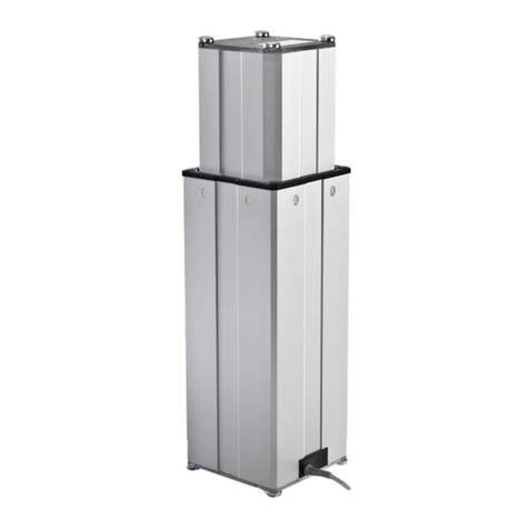
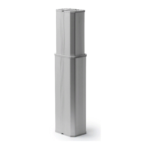
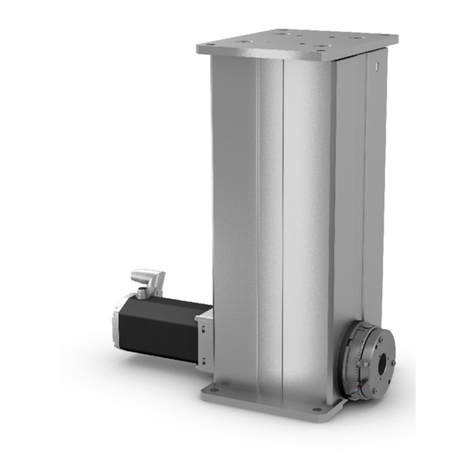
Ewellix CPMT User manual

INSTALLATION, OPERATION AND
MAINTENANCE MANUAL
Feature 1
max 2 lines
Feature 3
Feature 4
Feature 2
max 2 lines
CPMT
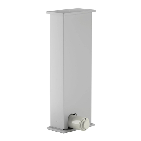
Telescopic pillar


33
Contents
1.0 General information......................................................4
1.1 Information in this manual ...............................................4
1.2 Explanation of symbols and signal words ......................4
1.3 Limitation of liability ........................................................5
1.4 Copyright.........................................................................5
1.5 Spare parts......................................................................5
1.6 Warranty terms................................................................5
1.7 Customer service ............................................................5
2.0 Safety .............................................................................6
2.1 Use ...................................................................................6
2.2 Responsibility of the owner and processor....................7
2.3 Personnel requirements..................................................7
2.4 Specic dangers .............................................................8
2.5 Safety equipment............................................................8
2.6 Safeguard against restart ...............................................8
2.7 Modications of device ...................................................9
2.8 Manufacturer’s declaration of EMC compliance............9
3.0 Technical data............................................................. 12
3.1 Ambient conditions ....................................................... 12
3.2 Product label................................................................. 12
4.0 Structure and function............................................... 13
4.1 Ov er v iew ........................................................................ 13
4.2 Brief description............................................................ 13
4.3 Requirements for third party control units (mandatory in
medical applications)........................................................... 15
4.4 Connections .................................................................. 15
4.5 Operating elements....................................................... 16
4.6 Options.......................................................................... 16
4.7 Accessories................................................................... 16
5.0 Transport, packaging and storage ........................... 17
5.1 Safety information for transportation............................ 17
5.2 Transport inspection..................................................... 17
5.3 Return to the manufacturer........................................... 17
5.4 Packaging...................................................................... 17
5.5 Storage.......................................................................... 18
6.0 Installation and rst operation ................................. 19
6.1 Installation location ....................................................... 19
6.2 Inspections prior to initial operation............................. 19
6.3 Installation.....................................................................20
6.4 Connection to the control unit ...................................... 21
6.5 Connection to operating element.................................22
6.6 Connection to power supply.........................................22
7.0 Operation .....................................................................23
7.1 Safety .............................................................................23
7.2 Turn on...........................................................................23
7.3 Turn o...........................................................................23
7.4 Actions before use.........................................................23
7.5 Actions during operation............................................... 24
7.6 Emergency disengagement .......................................... 24
8.0 Maintenance................................................................25
8.1 Maintenance plan..........................................................26
8.2 Maintenance work.........................................................26
8.3 Measures following completed maintenance...............27
9.0 Malfunctions................................................................28
9.1 Malfunction table...........................................................29
9.2 Start of operation after malfunction repair ...................29
10.0 Dismantling................................................................30
10.1 Dismantling..................................................................30
10.2 Disposal.......................................................................30
11.0 Appendix ....................................................................31
11.1 Technical data.............................................................. 31
11.2 Plans and diagrams.....................................................32
11.3 Approved accessories.................................................34
11.4 Declaration of incorporation........................................34
WARNING
Read this manual before installing, operating or maintaining
this telescopic pillar. Failure to follow safety precautions and
instructions could cause telescopic pillar failure and result in
serious injury, death or property damage. Keep this manual
nearby for future reference.

4
CPMT
1.0 General information
1.1 Information in this
manual
This manual provides important information on how to work
with the telescopic pillar (also called the device) safely and
eciently. The manual is part of the device, must always be
kept near the device and should be available for personnel
to read at any time. All personnel working with the device
must read and understand this manual before starting any
work. Strict compliance with all specied safety notes and
instructions is a basic requirement.
Moreover, the accident prevention guidelines and general
safety regulations applicable at the place of use of the de-
vice must also be complied with.
For better representation of circumstances, the illustrations
in this manual are not necessarily to scale and may vary
from the actual design of the device.
All information and notes in this manual were compiled with
due consideration given to applicable standards and regula-
tions, the present status of technology and our years of
knowledge and experience.
1.2 Explanation of symbols
and signal words
Safety precautions
Safety precautions are identied by symbols and signal
words dened on the right side of this page. These signal
words indicate the severity of the hazard. Adhere to these
safety precautions and take caution in order to avoid acci-
dents that may result in personal injury or damage to
property.
DANGER
Indicates a dangerous situation, which
will lead to death or serious personal
injury, if the precautionary measures are
ignored.
WARNING
Indicates a dangerous situation, which
can lead to minor or moderate injury or
property damage, if the precautionary
measures are ignored.
CAUTION
Indicates a dangerous situation, which
can lead to minor or moderate injury
the precautionary measures are ignored.
NOTE
Emphasizes useful hints and
recommendations as well as information
for ecient and trouble-free operation.

5
1.0 General information
1.3 Limitation of liability
All information and notes in this manual were compiled un-
der due consideration of valid standards and regulations, the
present state of technology and our years of experience.
The manufacturer will not be liable for injury or damage re-
sulting from:
• disregarding this manual
• unintended use
• employment of untrained personnel
• unauthorized conversions
• unauthorized technical modications
• manipulation or removal of the screws on the device
Where the telescopic pillar has been customized by Ewellix,
the actual product delivered may be dierent from what is
described in this manual. In this case, ask Ewellix for any ad-
ditional instructions or safety precautions relevant to this
product.
We reserve the right to make technical modications to the
telescopic pillar to improve usability.
1.4 Copyright
This manual is protected by copyright law and to be used
exclusively by Ewellix customers for internal purposes.
Passing this manual on to third parties, duplication of any
kind – even in the form of excerpts – as well as the use and/
or disclosure of the contents without the written consent of
the manufacturer, is not permitted, except for internal
purposes.
Violation of Ewellix’s copyright may become the subject of a
future claim for damages.
1.5 Spare parts
This telescopic pillar is designed to be repairable. Repairs
must only be carried out by persons authorized by the man-
ufacturer. All warranty and service claims become void with-
out notice, if any screws on the telescopic pillar have been
manipulated.
WARNING
Safety hazard caused by wrong spare parts
Wrong or faulty spare parts can adversely aect safety and
cause damage, malfunctions or total failure.
Therefore, follow the precautions below:
• Use only genuine spare parts from the manufacturer.
• Spare parts in/on the device may only be replaced by the manu-
facturer.
If the device cannot be repaired on site by authorised per-
sonnel, it must be dismantled from the application and sent
to the manufacturer.
1.6 Warranty terms
The applicable and eective warranty terms are those con-
tained in the manufacturer’s terms and conditions of sale
contained in the Ewellix sales contract that governs this
sale.
1.7 Customer service
Ewellix Customer Service is always available to provide
technical information and answer questions.
The contact information for Ewellix Customer Service can be
found on www.ewellix.com.

6
CPMT
6
2.0 Safety
2.1 Use
2.1.1 Intended use
The device has been designed and built exclusively for its
intended purpose as described in these instructions. The
device is to be used only for dynamic centric compression
or tensile-loaded lift of a load. It is intended for interior use
only.
The device has been designed for the movement of medical
equipment, specically medical procedure chairs and
tables.
2.1.1.1 Product service life
The telescopic pillar CPMT is designed for a service life of
10 years in a typical medical procedure equipment
application.
Product service life of the telescopic pillar CPMT depends
on the stroke and load of the application. According to the
L10 lifetime of the device, 56 000 cycles can be achieved in
an average medical procedure application (average load of
4 000 N and average stroke of 150 mm)
Some reference values for dierent stroke and load condi-
tions are given in the table below.
Lifetime [cycles] reference at given average load and stroke
Average load Fm4 000 N 5 000 N 6 000 N
CPMT1-XS0XXXFX-000
Stroke = 150 mm 42 000 23 000 14 000
Stroke = 300 mm 21 000 11 000 7 000
Stroke = 500 mm 12 000 7 000 4 000
CPMT1-XM0XXXFX-000
Stroke = 150 mm 56 000 30 000 18 000
Stroke = 300 mm 28 000 15 000 9 000
Stroke = 500 mm 17 000 9 000 5 000
2.1.2 Unintended use
Any use other than the intended use, or modications to the
device without the manufacturer’s written agreement, or op-
eration beyond the technical limits, is considered
unauthorized.
Specic application exemptions are:
• Flammable anaesthetic mixture with air
• Flammable anaesthetic mixture with oxygen or nitrous oxide
• Increased radiation
• Places exposed to water (wet rooms)
NOTE
Any unauthorized use of the device can cause personal injury
and property damage. Always adhere to the instructions given in
this manual.
2.1.3 Essential performance
The essential performance of the telescopic pillar CPMT is
moving or holding a load within the boundaries dened by
the device specications given in this operating manual and
the datasheet.

7
2.0 Safety
7
2.2 Responsibility of the
owner and processor
The device is designed for use in commercial applications
by its owner or processor.
The processor is the contracting partner of the reseller or
the manufacturer. The processor installs the device in a
complete system (application).
The owner or processor of the system is therefore subject to
the requirements of the Occupational Health and Safety Act.
In addition to the safety instructions in this manual, the
owner or processor must do the following, concerning safety
and accident prevention guidelines and environmental pro-
tection regulations, applicable to the site of the system’s
installation:
• Inform themselves of applicable industrial safety regula-
tions. They must also determine additional hazards that
arise due to the specic working conditions prevailing at
the site where the device is installed, using risk assess-
ment. The risk assessment must be implemented in the
form of work instructions for device operation.
• Conrm that the work instructions created for the system,
including the device, satisfy current legal requirements,
and if not, alter the instructions accordingly.
• Clearly regulate and specify the responsibilities for installa-
tion, operation, maintenance, and cleaning.
• Ensure that all employees who deal with the device have
read and understood this manual.
• Provide personnel with the required protective equipment.
• Provide training for personnel at regular intervals and in-
form personnel of the hazards.
In addition, the owner or processors must ensure that the
device is in adequate working condition. They must do the
following:
• Ensure that the maintenance intervals described in these
instructions are complied with.
• Have all safety devices inspected regularly for function and
completeness.
2.3 Personnel
requirements
WARNING
Improper installation, operation and maintenance can result in
serious injury, death or property damage.
Use only qualied, instructed or trained personnel (as described
below) who have read, understood and followed these
instructions.
2.3.1 Qualications
The following qualications are specied for dierent areas
of activity listed in this manual.
• An instructed person (operator): Instructed by the cus-
tomer in an orientation session on the assigned tasks and
possible dangers arising from improper behaviour.
• Qualied personnel: Based on their professional training,
know-how and experience, as well as knowledge of the
applicable standards and regulations, are able to inde-
pendently perform assigned work activities and to detect
and avoid possible dangers.
• Professional electrician: Based on his/her professional
training, know-how and experience, as well as knowledge
of the applicable standards and regulations, is able to in-
dependently perform work on electrical systems and to
detect and avoid possible dangers.
In addition, the professional electrician has been trained
for the special location where he/she works and knows the
relevant standards and regulations.
Only persons who can be expected to perform their tasks
reliably, are permitted to work with this device. Persons
whose reaction capabilities are impaired, through the use of
drugs, alcohol or medication for example, are not permitted.

8
CPMT
2.4 Specic dangers
The following section lists the residual risks that have been
determined by a risk assessment.
• Heed the safety instructions listed here, and the warnings
in sub-sequent chapters of this manual, to reduce health
hazards and to avoid dangerous situations.
WARNING
Danger of injury caused by moving components
Rotating and/or linearly moving components can cause serious
injury.
Therefore:
• Do not work on, or place, hands ,arms or any other parts of the
body, close to moving components.
2.5 Safety equipment
Integration of an emergency-stop system (for
certain applications)
The device is intended only for installation into an applica-
tion or system. It does not have its own operating control el-
ements, and does not have an independent emergency-stop
function. Therefore, the device must be installed so that it is
part of an emergency shut-o system and can be stopped if
necessary.
The emergency shut-o system must be connected in such
a way that any disruption of the power supply or reactivation
of the power supply after a power disruption, cannot cause a
hazardous situation for persons or objects.
The emergency shut-o system must always be freely ac-
cessible.
NOTE
The processor decides which applications require installation of
an emergency shut-o system.
Integration of a patient release system (for
certain applications)
The device is intended only for installation into an applica-
tion or system. It does not have its own operating control el-
ements, and does not have an independent patient release
mechanism. In the event of a malfunction, the device cannot
extend or retract.
If required by the application, a separate provision for pa-
tient release must be installed, to allow safe release of the
patient in case of emergency, or equipment failure.
NOTE
The processor decides whether the intended application requires
the installation of an emergency patient release system.
Integration of a safety mechanism to prevent
unintended triggering of the operating device
(for certain applications)
The device does not have its own operating control ele-
ments, and does not have a safety mechanism against unin-
tended triggering of the operating device.
If required by the application, a safety provision must be
provided to prevent unintended triggering of the operating
device.
NOTE
The processor decides whether the intended application requires
the installation of a safety mechanism to prevent unintended
triggering of the operating device.
The following safety mechanisms have been
installed:
• The telescopic pillar CPMT is tted with a thermoswitch in
the motor, which switches o the telescopic pillar if the
temperature reaches a certain threshold, in order to re-
duce the risk of re.
• Backup nuts are tted on the ballscrews to prevent the pil-
lar from collapsing if there is a ballscrew failure.
• End limit switches are installed to provide a safe current
cut-o when the end of stroke position of the device is
reached. In case of failure of the end limit switches, a me-
chanical safety end-stop prevents the device from exceed-
ing its intended stroke.
2.6 Safeguard against
restart
WARNING
Life-threatening situation through unauthorized restart
For work in hazard zones, there is a risk that the power supply
could be turned on without prior authorization. This presents
a potentially life-threatening situation for people in the hazard
zone.
• Read the information contained in this manual, concerning safe-
guarding against any unintentional restart of the power supply.
• Always follow the procedure as described below.
Protect CPMT against an unauthorised restart
Pull the power-line plug of the control unit attached to the
CPMT, out of the power outlet.

9
2.0 Safety
9
2.7 Modications of
device
WARNING
To avoid hazardous situations and to ensure optimal
performance, do not make any changes or modications to the
device unless they have been specically authorized by Ewellix.
2.8 Manufacturer’s
declaration of EMC
compliance
IEC/EN 60601-1-2:2007
Medical Electrical Equipment
Part 1-2: General requirements for safety
Additional standard: Electromagnetic
compatibility-requirements and tests
Guidance and manufacturer’s declaration – electromagnetic emissions (Table 1 - IEC 60601-1-2)
The telescopic pillar CPMT is intended for use in the electromagnetic environment specied below.
The customer or user of the telescopic pillar should ensure that it is used in such an environment.
Emissions test Compliance Electromagnetic environment – guidance
RF emissions CISPR 11 Group 1
The telescopic pillar CPMT uses only RF energy for internal function.
Therefore, RF emissions are very low and not likely to cause any interference
with nearby electronic equipment.
RF emissions CISPR 11 Class B
The telescopic pillar CPMT is suitable for use in all establishments, including
domestic establishments and those directly connected to the public low-
voltage power supply network that supplies buildings used for domestic
purposes.
Harmonic emissions
IEC 61000-3-2
Class A
Voltage uctuations/ icker
emissions
IEC 61000-3-3
Complies

10
CPMT
Guidance and manufacturer’s declaration – electromagnetic immunity (Table 2 - IEC 60601-1-2)
The telescopic pillar CPMT is intended for use in the electromagnetic environment specied below.
The customer or user of the telescopic pillar should ensure that it is used in such an environment.
Immunity test IEC 60601
test level
Compliance level Electromagnetic
environment – guidance
Electrostatic
discharge (ESD)
IEC 61000-4-2
± 6 kV contact
± 8 kV air
± 6 kV contact
± 8 kV air
Floors should be wood, concrete or
ceramic tile. If oors are covered with
synthetic material, the relative humidity
should be at least 30%.
Electrical fast
transient/burst
IEC 61000-4-4
± 2 kV for power
supply lines
± 1 kV for input/output
lines
± 2 kV for power
supply lines
± 1 kV for input/output
lines
Mains power quality should be that of
a typical commercial or hospital
environment.
Surge
IEC 61000-4-5
± 1 kV line(s) to
line(s)
± 2 kV line(s) to earth
± 1 kV dierential mode
± 2 kV common mode
Mains power quality should be that of
a typical commercial or hospital
environment.
Voltage dips, short
interruptions and
voltage variations
on power supply
input lines
IEC 61000-4-11
<5% U1
(>95% dip in U1)
for 0,5 cycle
40% U1
(60% dip in U1)
for 5 cycles
70% U1
(30% dip in U1)
for 25 cycles
<5% U1
(>95% dip in U1)
for 5 s
<5% U1
(>95% dip in U1)
for 0,5 cycle
40% U1
(60% dip in U1)
for 5 cycles
70% U1
(30% dip in U1)
for 25 cycles
<5% U1
(>95% dip in U1)
for 5 s
Mains power quality should be that of
a typical commercial or hospital
environment. If the user of the
telescopic pillar CPMT requires
continued operation during power
mains interruptions, it is recommended
that telescopic pillar CPMT is powered
from an uninterruptible power supply
or a battery.
Power frequency
(50/60 Hz)
magnetic eld
IEC 61000-4-8
3 A/m 3 A/m If distortion occurs, it may be
necessary to position the telescopic
pillar CPMT further from sources of
power frequency magnetic elds, or to
install magnetic shielding. The power
frequency magnetic eld should be
measured in the intended installation
location to ensure that it is suciently
low.
Note: U1 is the a.c. mains voltage prior to application of the test level.

11
2.0 Safety
11
Guidance and manufacturer’s declaration – electromagnetic immunity (Table 4 - IEC 60601-1-2)
The telescopic pillar CPMT is intended for use in the electromagnetic environment specied below.
The customer or the user of telescopic pillar should ensure that it is used in such an environment.
Immunity test IEC 60601
test level Compliance level Electromagnetic
environment – guidance
Conducted RF
IEC 61000-4-6
Radiated RF
IEC 61000-4-3
3 Vrms
150 kHz to 80 MHz
3 V/m
80 MHz to 2,5 GHz
3 Vrms
3 V/m
Portable and mobile RF communications equipment should be
used no closer to any part of the telescopic pillar CPMT, including
cables, than the recommended separation distance calculated
from the equation applicable to the frequency of the transmitter.
Recommended separation distance
d = 1,2 √P
d = 1,2 √P 80 MHz to 800 MHz
d = 2,3 √P 800 MHz to 2,5 GHz
where P is the maximum output power rating of the transmitter in
watts (W) according to the transmitter manufacturer and d is the
recommended separation distance in meters (m). Field strengths
from xed RF transmitters, as determined by an electromagnetic
site survey1), should be less than the compliance level in each
frequency range2). Interference may occur in the vicinity of
equipment marked with the following symbol:
Note 1: At 80 MHz and 800 MHz, the higher frequency range applies.
Note 2: These guidelines may not apply in all situations. Electromagnetic propagation is aected by absorption and reection from structures, objects and people.
1) Field strengths from xed transmitters, such as base stations for radio (cellular/cordless) telephones and land mobile radios, amateur radio, AM and FM radio
broadcast and TV broadcast cannot be predicted theoretically with accuracy. To assess the electromagnetic environment due to xed RF transmitters, an electromagnetic site survey
should be considered. If the measured eld strength in the location in which the telescopic pillar CPMT is used exceeds the applicable RF compliance level above, the Model 006
should be observed to verify normal operation. If abnormal performance is observed, additional measures may be necessary, such as re-orienting or relocating the telescopic pillar
CPMT.
2) Over the frequency range 150 kHz to 80 MHz, eld strengths should be less than 3 V/m.
Recommended separation distances between portable and mobile RF communications equipment and the
telescopic pillar CPMT (Table 6 – IEC 60601-1-2)
The telescopic pillar CPMT is intended for use in an electromagnetic environment in which radiated RF disturbances are controlled. The
customer or user of the telescopic pillar CPMT can help prevent electromagnetic interference by maintaining a minimum distance
between portable and mobile RF communications equipment (transmitters) and the telescopic pillar CPMT as recommended below,
according to the maximum output power of the communications equipment.
Rated maximum output
power of transmitter [W]
Separation distance according to frequency of transmitter [m]
150 kHz to 80 MHz
d = 1,2 √P
80 MHz to 800 MHz
d = 1,2 √P
800 MHz to 2,5 GHz
d = 2,3 √P
0,01 0,1 0,1 0,2
0,1 0,4 0,4 0,7
11,2 1,2 2,3
10 3,8 3,8 7,3
100 12,0 12,0 23,0

12
CPMT
Fig. 2
CPMT1-1S0400F1-000 N0L012345678
24V–30V =
max.5000Npush max.4000Npull
SWISS MADE
Bj:03.14
400mm IP20
12A Int. 1min/9min
i
CUS
Ewellix (Liestal) AG, CH-4410 Liestal
Type label (without options):
1. Type designation
2. Manufacturer
3. Maximum current consumption
4. Serial number
5. Duty cycle of operation (ON/OFF time)
6. IP protection class
7. Indoor use only
8. CE mark
9. UL test mark
10. Recommendation to read operating manual
11. Disposal information
12. Date of manufacture (month, year)
13. Manufacturer’s address
14. Maximum stroke
15. Pull force
16. Push force
17. Voltage
NOTE
The technical data (dimension, weight, output, connection
details etc.) can be found in the appendix.
3.1 Ambient conditions
Operation
• Indoor use only at: Operation
• Ambient temperature +10 to +40 °C.
• Atmospheric humidity max 90%
• Air pressure from 700 to 1 050 hPa
• Overvoltage Category I device
• Pollution degree 2
Storage/transport
• Temperature –20 to +60 °C
• Atmospheric humidity from 0% to 90%, non-condensing
• Air pressure from 700 to 1 050 hPa
3.2 Product label
The type label (g. 1 and g. 2) is located on the outer tube
and contains the following information:
Fig. 1
3.0 Technical data
1 2 4
5
6
7
8910111213
14
15
16
17
3
Position of type
label
Position of
logo

13
4.0 Structure and function
Fig. 4
Outer tube base plate
b1. Threads M10 for mounting screws
b2. Centering screws for plates on tube
b3. Attachment of ballscrew to base plates
b4. Hole on outer tube base plate – no function
c1. Areas of force distribution
c2. Areas of force distribution
4.2 Brief description
The functional principle of the telescopic pillar CPMT is
based on a push or pull force for the movement of centric
and eccentric loads. The CPMT requires an external control-
ler for it to be operational.
A DC gear motor attached to the middle tube drives two
spindle nuts simultaneously via a spur gear. The rotation of
the nuts induces a linear motion of the two ballscrews in op-
posing directions. The ballscrews are attached to the base
plates and cause an extension or retraction of the telescopic
tubes depending on the direction of motion. A built-in brake
holds the position at a standstill or during power cut.
4.0 Structure and function
4.1 Overview
Fig. 3
a1. Outer tube base plate
a2. Motor cable
a3. Outer tube
a4. Middle tube
a5. Inner tube
a6. Rim covers
a7. Glide pads
a8. Inner tube base plate
a9. Mechanical safety end stop
a8
a5
a7
a6
b1 b1
c1c1
c1
c1
c2
b1
b1
c1c1
b1
b1
b4
b2
b2
b2
b2
b3
a9
a2
a4
a3
a1
Inner tube base plate

14
CPMT
Outer tube base plate (a1)
The outer tube base plate has four holes to access attach-
ment bores in the outer tube (b1) for the mounting screws.
This enables the pillar to be fastened to one side of the ap-
plication. The outer tube base plate must be attached per-
manently with fastenings screws M10 to a metal plate in the
application, which has to support the areas of force distribu-
tion (c1, c2).
Motor cable (a2)
The cable (a2) exits to one side at the outer tube base plate
(a1) and has to be connected to an external control unit via
the DIN-8 plug or the ying leads cable attached.
Outer tube (a3)
The outer tube is the tube with the largest outside dimen-
sions. The CPMT pillar can be mounted in any orientation to
place the outer tube (a3) at the top or bottom of the
application.
Middle tube (a4)
The middle tube is the tube between the outer and inner
tubes.
Inner tube (a5)
The inner tube is the tube with the smallest outside dimen-
sions. The CPMT pillar can be mounted in any orientation to
place the inner tube (a5) at the top or bottom of the
application.
Rim covers (a6)
The purpose of the rim covers for the outer and middle tube
is to protect the tube guiding system from dust and to pre-
vent the ingress of foreign matter. The rim covers must not
be removed under any circumstances.
Glide pads (a7)
The purpose of the glide pads (a7) is to provide a sti, virtu-
ally play-free guiding of the tube sets.
Inner tube base plate (a8)
The inner tube base plate has four holes to access attachment
bores in the inner tube (b1) for the mounting screws. Its pur-
pose is to fasten the pillar to one side of the application. The
inner tube base plate must be attached permanently with fas-
tenings screws M10 to a metal plate in the application, which
has to support the areas of force distribution (c1, c2).
Mechanical safety end-stops (a9)
The purpose of the mechanical safety end-stops (a9) is to
block the extension of the tubes in the event of failure of the
end limit switches. This is a safety mechanism only.
Areas of force distribution (c1, c2)
The outer and inner tube base plates must be attached to a
support plate in the application. The areas of force distribu-
tion have to be supported in the application by an ade-
quately dimensioned support plate covering these areas.
This support plate must not be removed under any
circumstances.
Guide tube unit
The guide tube unit is made up of the outer tube (a3), middle
tube (a4) and inner tube (a5), and its purpose is to carry cen-
tric and eccentric loads.
Drive unit
The permanent magnet motor is a 24–30 V DC gear motor
and drives the ballscrews via a spur gear. The speed of the
movement depends on the load and the direction of the
movement. The motor and spur gear are attached to the
middle tube (a4).
Spur gear
The spur gear drives the ballscrews. It is driven via the per-
manent magnet motor.
End positions
The stroke is limited by the integrated end limit switches that
cut the power to the DC gear motor. If the CPMT moves be-
yond the end limit switches (in the event of a malfunction), a
mechanical safety end stop (a9) halts the movement.
Thermo-switch
The thermo-switch in the motor, controls thermal and electri-
cal overload and switches o the permanent magnet motor if
it overheats. The pillar cannot be operated again until the
drive temperature has fallen below the switching threshold.
Brake
The brake is attached to the gear motor. Its purpose is to
block the movement of the pillar during standstill or if the
power supply to the motor is cut.
External control unit
The DC gear motor is fed via an external control unit through
the cable connection (a2). The control unit controls the run-
ning direction of the telescopic pillar. An integrated 2-hall
encoder on the motor can be accessed by the controller to
enable variable speed control or positioning.
NOTE
Additional variations between CPMT pillars are given in the
appendix.

15
4.0 Structure and function
4.3 Requirements for
third party control units
(mandatory in medical
applications)
Control units not approved by Ewellix for CPMT pillars, are
treated as third party control units.
NOTE
It is strongly recommended to use original Ewellix controls for
the operation of the CPMT pillar. If third party controls are used,
there must be good documented evidence that the requirements
listed below are complied with.
The secondary circuit of third party control units must be
designed as an overvoltage category 1 circuit. The third
party control unit must be tted with an overload safety cut-
o. The maximum power input to the device should be only
0.5 A above the nominal value. The maximum shut-o value
may be only 1 A above the nominal value. For example: The
maximum power consumption is 12 A. The recommended
shut-o value is 12,5 A, the maximum cut-o value is 13 A.
NOTE
The current cut-o has to be set dierently if the main load
direction is in pull mode. Consult the Technical Data or
datasheet in this manual, for maximum power consumption
values for each type.
The third party control must enable the drive to draw cur-
rents up to 25 A for 200 ms after switching on (start-up cur-
rent). The excess power shut-o feature can also be tempo-
rarily de-activated for this purpose.
The operating voltage of the CPMT pillar is 24-30 V DC. The
no-load voltage of 36 V DC must not be exceeded. After the
system has been installed, ensure electro-magnetic compati-
bility. The operating time and duty cycle of the CPMT pillar may
not be exceeded (⮑ “Technical data”, Appendix, page 31).
NOTE
The third party power supply must have an isolation between
the primary and secondary circuits according to 2 MOPP, and
provide a non-grounded secondary circuit.
Push-to-run operation (recommended): The pillar operates
as long as the switch is pressed. The device does not have
signals to indicate operation, and depending on the applica-
tion, it is recommended to have an operational signal in-
stalled in the third party control unit.
For the 2-Hall encoder impulse transmitter, the third party
control unit must fulll the following additional requirements:
• Feed the hall sensors with a current of 4,5–26,5 V DC and
a current limit of no more than 200 mA.
• Load the hall sensor outlets with a maximum of 20 mA.
• Connect the hall sensor outlets to the supply with pull-up
resistors so that the signal of the open collector outlets
can be analyzed.
4.4 Connections
Electrical connection
The telescopic pillar is connected to the control unit via the
DIN-8 plug or the ying leads cable.
Connected load is 24 V–30 V DC and up to 12 A according
to the technical data (⮑ Appendix, page 31).
Important: Ensure that cables cannot get pinched or dam-
aged. Check that the mains voltage corresponds to the
nominal values on the type plate.
Fig. 5
Pin allocation and lead color code are given in the technical
specication in the appendix.

16
CPMT
Fig. 6
Mechanical connections
101
101
146
146
M10
15
50
M10
35
Important: Ewellix will not accept liability for any damage
caused if the telescopic pillar CPMT is not used with a suita-
ble operating device and supporting metal plates on outer
and inner tube base plates.
4.5 Operating elements
Requirements for operating elements
(mandatory in medical applications):
General safety requirements according to IEC 60601-1 cur-
rently valid edition, harmonized with national directives
(Means of protection:
1 Means Of Patient Protection [MOPP]).
Suitable Ewellix operating elements are listed in the section
Accessories.
4.6 Options
Options can be recognized from the type designation on the
type plate.
Voltage
The option voltage denes the use for 24-30 V DC.
Load
The CPMT is available in two standard load options, 5000 N
or 6000 N push force. Pull load is 4000 N for both options.
Retracted length
Two standard retracted length options are available, dened
by the relationship to the stroke of the pillar. The options to
choose from are ‘stroke/2 + 120 mm’ or ‘stroke/2 + 240 mm’.
Stroke length
The available stroke length for CPMT is from 300 mm to 600
mm in 10 mm steps for retracted length ‘stroke/2 + 240 mm’,
and from 400 mm to 600 mm in 10 mm steps for retracted
length ‘stroke/2 + 120 mm’
Electrical options
The CPMT pillar comes equipped as standard option with a
2-hall encoder and end limit switches.
Cable options
Available cable options are: With DIN-8 cable, in lengths of
1m or 2.3m; or with ying leads termination, in length of
2.3m.
4.7 Accessories
Mounting plates
The purpose of the mounting plates is to ensure that the pil-
lar is fastened securely to the application and the force entry
points to the pillar are well-supported. The base and top
plates must be fastened to the mounting plates with four
fastening screws M10.
Further details on accessories can be found in the appendix
(⮑ Approved accessories, page 34).
Important: Ewellix will not accept liability for any damage
caused if the telescopic pillar CPMT is not used with a suita-
ble Ewellix operating device or accessory.
WARNING
The use of accessories and cables other than those
recommended by Ewellix for this device, may result in increased
emissions or decreased immunity of the device.
Outer tube section base plate
Inner tube section base plate
Mounting
plate
(accessory)

17
5.0 Transport, packaging and storage
5.0 Transport, packaging and
storage
5.1 Safety information for
transportation
CAUTION
Damage due to improper transport
Signicant damage to the device may occur as a result of
improper transport.
Therefore:
• Proceed carefully during delivery and unloading of the packaged
items, as well as during transport to nal destination. Comply with
the symbols and information shown on the packaging.
• Do not remove the telescopic pillar CPMT from its packaging until
just before installation.
• Note storage requirements for return transport of the device to
the manufacturer (⮑ Storage, page 18)
5.2 Transport inspection
The telescopic pillar is delivered as one packaged unit in a
box or on pallets.
Check the delivery immediately upon receipt, for complete-
ness and any signs of damage incurred during transport.
Check completeness of delivery for:
• A complete pillar unit with built-in options as dened by
the type key on the type plate.
• Installed cable and low voltage connector (depending on
the option chosen, with DIN-8 connector or ying leads)
• Additional accessories (only if selected at time of pur-
chase)
If exterior transport damage is evident:
• Do not accept delivery or do so only under agreed condi-
tions.
• Record scope of damage on the transport documents or
bill of delivery of the shipping company.
• Initiate complaint.
NOTE
Report any damage as soon as possible, as damage claims can
only be submitted within the transporter’s applicable complaint
period.
5.3 Return to the
manufacturer
If device is damaged, arrange for return transport as follows:
1. Dismantle the device if necessary (⮑ Dismantling,
page 30).
2. Pack device in its original packaging. Follow storage
conditions (⮑Storage, page 18).
3. Send to manufacturer. Contact Ewellix service to obtain
a shipment address.
5.4 Packaging
Requirements:
All parts are packaged appropriately for anticipated trans-
port conditions, using only environmentally-friendly packag-
ing materials.
The packaging is intended to protect the individual components
from damage caused during transport, or by corrosion and other
potential hazards, until the components are ready for installation.
Only remove packaging shortly before installation. The packag-
ing should not be destroyed, but kept for possible return ship-
ment to the manufacturer (⮑ Chapter 5.3, page 17).
If the packaging is to be disposed of, please note and ad-
here to the following:
NOTE
Environmental damage due to incorrect disposal
Packaging material consists of valuable raw materials, much of
which can eectively be recycled and reused.
Therefore:
• Dispose of packaging material in an environmentally correct way
• Comply with locally applicable disposal regulations.

18
CPMT
5.5 Storage
Pack the device in its original packaging for storage
• Do not store outside.
• Dry and dust-free storage.
• Keep away from any aggressive media.
• Protect from UV radiation.
• Avoid mechanical vibrations.
• Ambient storage conditions according to section Storage.
• For storage longer than three months, check the general
condition of all parts of the packaging on a regular basis.
NOTE
There may be notices on the packaging concerning additional
storage requirements not listed here. If so, follow these
accordingly.

19
6.0 Installation and first operation
6.0 Installation and rst operation
Authorized personnel
• The installation and rst start of operation may only be
conducted by qualied personnel.
• Work on the electrical system may only be performed by
professional electricians.
WARNING
Electric shock and moving parts hazards
Serious injury or death can be caused by touching live electrical
components and by unexpected movement of the telescopic
pillar.
Be sure the system’s power supply is o and the device is
locked out before installing.
WARNING
Danger if restarted without authorization
When correcting faults there is risk of the energy supply being
switched on without authorization. This poses a life threatening
hazard for persons in the danger zone.
Therefore:
• Prior to starting work, switch o the system and be sure it is
locked out.
WARNING
Installation adjacent to other equipment
The device should not be installed adjacent to or stacked with
other equipment. If adjacent or stacked use is necessary, the
device should be trialled under observation, to verify normal
operation in the conguration in which it will be used.
WARNING
Special precautions regarding EMC
The device requires special precautions regarding EMC and
must be installed and put into service according to the EMC
information provided in this operating manual (⮑ Safety, page
6)
WARNING
Risk of injury and device damage due to incorrect
installation of the optional devices
Therefore:
• Optional devices, in particular components that are part of a ret-
rot, may only be installed in accordance with respective instruc-
tions (circuit diagram).
• Electromagnetic compability must be tested for the routing, and
appropriate corrective measures carried out if necessary and as
described in the device’s operating manual.
6.1 Installation location
• Adhere to the technical data for operating conditions.
• Install in a location according to the ambient operating
conditions dened in the section Ambient Conditions.
6.2 Inspections prior to
initial operation
• To be performed by a professional electrician
Prior to rst operation, a professional electrician must per-
form and document the following tests and readings:
• Visual condition check
• Function check of operating features and safety features
• Reading of leakage currents
• Reading of insulation resistance
NOTE
Additional information concerning inspections and readings
(⮑ Maintenance, page 25)

20
CPMT
6.3 Installation
• To be performed by qualied personnel.
WARNING
Risk of injury and device damage due to manipulation of the
screws on the device
Manipulation or loosening of the screws on the device or the optional
devices may lead to injury and device damage during the operation.
Therefore:
• Never loosen screws on the device or the options, except the
transportation screws installed in the mounting bores.
6.3.1 Installation overview
The telescopic pillar CPMT can be mounted to the application
via the Ewellix mounting plates available as accessory, or di-
rectly to the application. Mounting has to be done via the at-
tachment bores on the outer and inner tube, which are acces-
sible through the top and base plates (⮑ g. 1, page 12).
Screw 8 × M10
Screw-in depth 25 to 35 mm in the pillar
Strength class 10,9
Tightening torque 40 Nm
CAUTION
The outer and inner tube base plates are not designed to
support the rated load of the pillar without additional support
provided by mounting plates. If a custom mounting plate is used,
ensure that it is dimensioned to provide sucient support of the
base plates.
The telescopic pillar CPMT can be mounted with the outer tube
or the inner tube at the bottom. If the inner tube is xed and the
outer tube is able to move in the application, ensure that there
is no possibility of strain or pinching of the power cable.
Any subsequent fastening bores in the aluminium tubes may
be made only by Ewellix.
Care must be taken not to damage or scratch the sides of
the tubes, as this can damage the guiding system and lead
to product malfunctions.
6.3.2 Installation steps
1. Remove the transportation screws from the mounting
bores at the outer and inner tube base plates.
2. Fasten the mounting plates, or the attachment points in
the application, to the mounting bores at the outer and
inner tube base plates.
Important: Screw in to a minimum of 25 mm and torque the
screws with 40 Nm.
NOTE
Fastening screws are not supplied. The bore dimensions can be
found in ⮑Plans and diagrams, page 32.
3. Check that all screws are suciently secured against
self-loosening.
4. Check that all interfaces and connections have been
mounted and/or connected correctly.
5. Ensure that the motor cable cannot be crushed, jammed
or pulled during operation, due to tension or pressure.
6. You are now ready to connect and operate the telescopic
pillar using the corresponding control unit and operating
device.
Before connecting the telescopic pillar CPMT to a control
unit, ensure that:
• the telescopic pillar CPMT is attached to the metal plates
of the application on both sides
• all attachment points are securely screwed to the application
• the elements are fully aligned and seated at the top and
bottom
• the areas for force distribution are supported
• the acting force does not impact the guide tubes with inad-
missibly high values, as side-impacting forces that are too
high can destroy the telescopic pillar CPMT
• the telescopic pillar is not obstructed in any way in the en-
tire lifting area
• the cables are not pinched, or caught or subject to tension,
bending, or pull stress.
WARNING
Risk of injury and device damage due to insucient
fastening
Use fastening bolts only, and secure them adequately. Do not
use screws to install. Never loosen or otherwise manipulate
screws on the device or options.
WARNING
Risk of injury through moving parts
When retracting, there is a risk of crushing between the mounting
plate and the tube end of the telescopic pillar.
Therefore:
• When retracting, ensure that no objects or parts of the body, such as
hands or ngers, can be caught between the mounting plate (2) of
the inner tube and the ends of the outer tubes (1) (⮑ g. 1, page 12).
• If necessary, install a mechanical safety device depending on the
installation location.
• If the device has been delivered with optional fastening bores, en-
sure that the intended parts have been correctly tted to these
bores and that the bores are not accessible to any objects or
parts of the body.
Ensure that the telescopic pillar CPMT is not obstructed in
its movement over the entire stroke area. Consider perform-
ing collision tests on the application.
Table of contents
Other Ewellix Lifting Column manuals