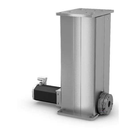
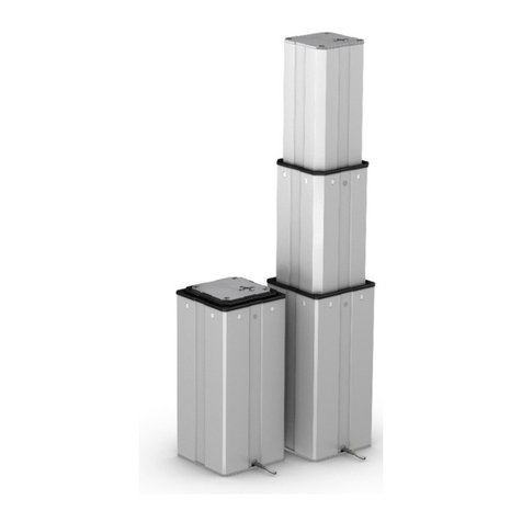
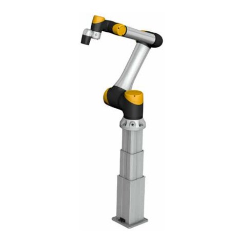
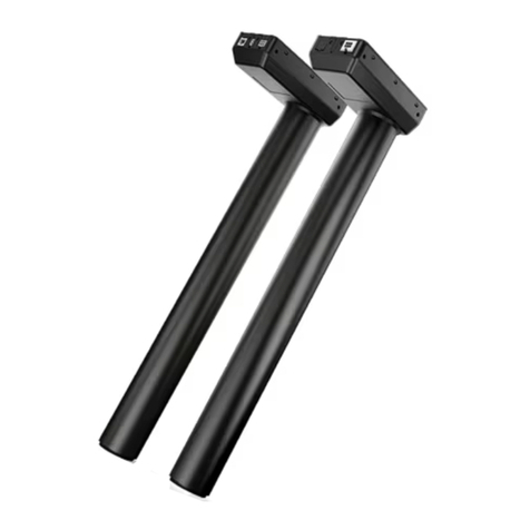
Ewellix THG User manual

CATEGORY
MAX 2 LINESINSTALLATION, OPERATION AND MAINTENANCE MANUAL
THG/TLG/TLT
Telescopic pilars


33
Contents
1.0 General information ...................................................4
1.1 Information on this manual ..........................................4
1.2 Explanation of symbols and signal words ...................4
1.3 Limitation of liability .....................................................5
1.4 Replacement parts.......................................................5
1.5 Warranty terms.............................................................5
1.6 Customer service .........................................................5
2.0 Safety ...........................................................................6
2.1 Intended use.................................................................6
2.1.1 Expected life time......................................................6
2.1.2 Essential performance ..............................................6
2.2 Responsibility of the owner and processor.................6
2.3 Personnel requirements...............................................7
2.4 Specicdangers ..........................................................7
2.5 Safety device................................................................8
2.6 Safeguard against restart ............................................8
2.7 Modicationsofdevice ................................................8
3.0 Technical data.............................................................9
3.1 Safety equipment .........................................................9
3.2 Operating conditions....................................................9
3.3 Type label .....................................................................9
4.0 Structure and function.............................................10
4.1 Telemag THG, TLG..................................................... 10
4.2 Telemag TLT ............................................................... 11
4.2.1 TLT1 ......................................................................... 11
4.2.2 TLT2 ........................................................................ 12
4.3 Brief description ......................................................... 13
4.4 Functional principle .................................................... 13
4.5 Connections ............................................................... 13
4.6 Operating elements.................................................... 14
4.7 Options ....................................................................... 14
4.7.1 Impulse transmitter.................................................. 14
4.7.2 Potentiometer.......................................................... 14
4.7.3 Cable feed ............................................................... 14
4.8 Accessories................................................................ 14
4.9 Danger zones ............................................................. 15
4.9.1 Danger zone THG; TLG; TLT1................................. 15
4.9.2 Danger zone TLT2................................................... 15
5.0 Transport, packaging and storage......................... 16
5.1 Safety information for transport................................. 16
5.2 Transport inspection .................................................. 16
5.3 Return shipment to the manufacturer........................ 16
5.4 Packaging................................................................... 16
5.5 Symbols on the packaging ........................................ 17
5.6 Storage ....................................................................... 17
6.0 Installation and initial operational set-up ............. 18
6.1 Safety.......................................................................... 18
6.2 Installation position .................................................... 18
6.3 Inspectionpriortorstoperation .............................. 18
6.4 Installation .................................................................. 18
6.5 Connection to the control unit ................................... 21
6.5.1 Connect jack plug to control unit ...........................22
6.5.2 Connect DIN-8 plug to control unit........................23
7.0 Operation...................................................................24
7.1 Safety.......................................................................... 24
7.2 Turnonando ........................................................... 24
7.3 Precautions prior to use............................................. 24
7.4 Normal operation .......................................................24
7.5 Precaution after use ...................................................25
7.6 How to stop device in case of emergency.................25
7.6.1 Shut down the telescopic pillar...............................25
7.6.2 Pull jack plug out of the KOM control unit.............. 25
7.6.3 Pull the DIN-8 plug out of the BCU/VCU/SCU
control unit........................................................................26
7.7 After use .....................................................................26
8.0 Maintenance..............................................................27
8.1 Safety..........................................................................27
8.2 Maintenance plan.......................................................28
8.3 Maintenance work......................................................28
8.3.1 Cleaning ..................................................................29
8.3.2 Visual inspection ....................................................29
8.4 Actions after maintenance has been completed.......29
9.0 Malfunctions .............................................................30
9.1 Safety..........................................................................30
9.2 Troubleshooting chart ................................................ 31
9.3 Start of operation after fault has been eliminated .....32
10.0 Dismantling and disposal........................................33
10.1 Safety..........................................................................33
10.2 Dismantling.................................................................33
10.2.1 Dismantling the telescopic pillar...........................33
10.2.2 Pull the jack out of the KOM
control unit........................................................................33
10.2.3 Pull the DIN-8 plug out of the BCU/ VCU/SCU con-
trol unit..............................................................................34
10.3 Disposal......................................................................34
11.0 Appendix....................................................................35
WARNING
Read this manual before installing, operating or maintaining this
actuator. Failure to follow safety precautions and instructions could
cause actuator failure and result in serious injury, death or property
damage.
4
THG/TLG/TLT
1.0 General information
1.1 Information on this
manual
This manual provides information necessary for the proper
and safe installation, operation, maintenance, dismantling
and disposal of this pillar (also called device). It is an integral
part of the equipment, and must be kept so that it is acces-
sible to personnel.
Before doing anything with this device, personnel must read
this manual thoroughly and understand its contents.
Compliancewithallspeciedsafetyinstructionsandoperat-
ing instructions is vital for safe and proper use of this device.
In addition, national and local governmental accident pre-
vention regulations and general safety instructions must be
observed in the area where this device is being used.
Illustrations in this manual are intended to facilitate a basic
understandingoftheseconceptsandmaydierfromthe
actual design.
1.2 Explanation of symbols
and signal words
Safety precautions
Safetyprecautionsinthismanualareidentiedbysymbols
and signal words. These signal words (shown to the right) in-
dicates the severity of the hazard.
Adhere to these safety precautions and act cautiously in or-
der to avoid accidents resulting in personal injuries and
damage to the device and the equipment into which it has
been installed.
DANGER
Indicates a dangerous situation, which
will lead to death or serious personal
injury, if the precautionary measures are
ignored.
WARNING
Indicates a dangerous situation, which
can lead to minor or moderate injury or
property damage, if the precautionary
measures are ignored.
CAUTION
Indicates a dangerous situation, which
can lead to minor or moderate injury
the precautionary measures are ignored.
NOTICE
Indicates information considered
important, but not hazard-related (e.g.
messages relating to property damage).
NOTE
Emphasizes useful hints and
recommendations as well as information
forecientandtrouble-freeoperation.

5
1.0 General information
1.3 Limitation of liability
All information and notes in this manual were compiled un-
der due consideration of valid standards and regulations, the
present status of technology and our years of knowledge
and experience.
The manufacturer will not be liable for damage resulting
from:
• disregarding this manual
• unintended use
• employment of untrained personnel
• unauthorized retooling
• unauthorized technical changes to device
• use of unapproved spare parts
When ordering options for custom models or from the latest
technicalchanges,theactualdeliveredproductmaydier
from the explanations and illustrations in this manual.
The obligations agreed to in the contract for delivery, the
general terms and conditions of Ewellix and the manufac-
tureraswellasthelegalregulationswhichwereineectat
the time the contract was entered into shall apply.
Wereservetherighttomaketechnicalmodicationsinorder
to impove usability.
1.4 Replacement parts
The telescopic pillar is not designed for repair work by the
owner/operator. All warranty and service claims are void if
repairs are not performed by the manufacturer or another
entity approved by the manufacturer.
WARNING
Risk of injury through the use of incorrect replacement
parts
Installation or use of incorrect replacement parts may result in
safety risks for personnel and may also cause damage, malfunction
or complete failure of the drive.
Therefore:
Defective original parts for the pillar must only be replaced by the
manufacturer.
To have defective original parts replaced, the pillar must be
uninstalled and sent to the manufacturer.
1.5 Warranty terms
The warranty terms are included in the manufacturer’s Terms
and Conditions contained in the Ewellix sales contract that
governs this sale.
1.6 Customer service
Ewellix Customer Service is always available to provide
technical information and answer questions.
The contact information for Ewellix Customer Service can be
found on www.ewellix.com.
In addition, our employees are always interested in acquiring
new information and experience gained from practical appli-
cation; such information and experience may help improve
our products.

6
THG/TLG/TLT
6
2.0 Safety
This section provides an overview of all the main safety as-
pects of installing, operating, and maintaining this device.
Failure to comply with the guidelines and safety instructions
contained in this manual may result in serious hazards that
could cause possible serious injury or death or damage to
the device or equipment.
2.1 Intended use
The telescopic pillars – THG, TLG, and TLT – have been de-
signed and built exclusively for the intended purposes as
described below.
• These pillars are to be only used for a dynamic centric and
ocenterliftchargedwithpressure.
• These pillars have been especially designed for height ad-
justments of medical applications, computer work and as-
sembly tables. Any other use of these pillars must be au-
thorized by the manufacturer; see cover back for the
address.
• These pillars are only suitable for indoor applications and
may not be exposed to:
-Environmentwithammableanestheticorotheramma-
ble substances.
-Environment with enriched oxygen concentration
-Environment with enriched radiation
-Wet room environment
Any use that extends beyond the intended use or a use dif-
ferent than the one described above is deemed misuse.
WARNING
Risk from misuse
Any utilization of this device beyond its intended purpose or a
different use of this device may potentially lead to hazardous
situations.
Any type of claims resulting from damage caused by misuse
are excluded.
2.1.1 Expected life time
The product is designed for a lifetime of 20 000 cycles at
300 mm load with centric load operated according to the
specicationsseeninthedatasheetsor10years.
2.1.2 Essential performance
Holding and moving of loads
2.2 Responsibility of the
owner and processor
The device is designed for use in commercial applications
by its owner or processor.
The processor is the contracting partner of the reseller or
the manufacturer. The processor installs the device in a
complete system (application).
The owner or processor of the system is therefore subject to
the requirements of the Occupational Health and Safety Act.
In addition to the safety instructions in this manual, the
owner or processor must do the following, concerning safety
and accident prevention guidelines and environmental pro-
tection regulations, applicable to the site of the system’s
installation:
• Inform themselves of applicable industrial safety regula-
tions. They must also determine additional hazards that
ariseduetothespecicworkingconditionsprevailingat
the site where the device is installed, using risk assess-
ment. The risk assessment must be implemented in the
form of work instructions for device operation.
• Conrmthattheworkinstructionscreatedforthesystem,
including the device, satisfy current legal requirements,
and if not, alter the instructions accordingly.
• Clearly regulate and specify the responsibilities for instal-
lation, operation, maintenance, and cleaning.
• Ensure that all employees who deal with the device have
read and understood this manual.
• Provide personnel with the required protective equipment.
• Provide training for personnel at regular intervals and in-
form personnel of the hazards.

7
2.0 Safety
7
In addition, the owner or processors must ensure that the
device is in adequate working condition. They must do the
following:
• Ensure that the maintenance intervals described in these
instructions are complied with.
• Have all safety devices inspected regularly for function and
completeness.
2.3 Personnel requirements
WARNING
Danger of injury if personnel are insufficiently qualified
If unqualified personnel install, operate, or maintain the device or
are in the appliance’s danger zone, hazards may arise which can
cause serious injury and substantial damage to property.
This manual species the personnel qualications re-
quired for the dierent areas of work, listed below:
Operator
Theoperatorispartofthestaoftheoperatingcompany
and has been trained by the operating company. The opera-
tor is familiar with the regulations that apply at the operating
site of the machine and has been informed about the haz-
ards imposed by the entire system.
Theoperatoralsohasbeenveriablytrainedbytheoperating
company and based on this training he/she is able to safely
• operate the equipment,
• eliminatespecicdisruptions,
• carryoutspecicmaintenancework.
Qualied electrician
Based on his technical training, knowledge, experience and
knowledge of the applicable standards and regulations, the
Qualiedelectricianisabletoperformworkonelectrical
systems and recognise and avoid potential hazards himself.
Thequaliedelectricianisspeciallytrainedfortheareaof
responsibility he is involved with and knows the relevant
standards and regulations.
Thequaliedelectricianmustcomplywiththerequirements
of the applicable legal regulations for accident prevention.
Qualied personnel
Qualiedpersonnelisabletocarryoutassignedworkandto
recognize and prevent possible dangers self-reliantly due to
its professional training, knowledge and experience as well
as profound knowledge of applicable regulations.
User
The user uses and operates the pillar for its intended pur-
pose without other prior knowledge.
The workforce must only consist of persons who can be ex-
pected to carry out their work reliably. Persons with impaired
reactions due to, for example, the consumption of drugs, al-
cohol, or medication are prohibited.
2.4 Specic dangers
Thefollowingsectionspeciesresidualriskswhichmayre-
sult from using the pillar and have been established by
means of a risk assessment.
WARNING
Safety considerations
• If operated with a non Ewellix control unit the secondary circuit of
the controller must secure a double isolation (2 MOPP) from main
supply including a PE (earth ground)
• If external fuses are needed in medical applications they must core-
spondtoIEC60127withacurrentswitchocapabilityof1500A
• The risk of a delay between stopping signal and physical stop of
the product must be considered before usage
• The product does not contain means to release person.
• The product is intended to operated only in "touch mode".
In case of any defect the pillar has no further lifting function. If
this can cause a risk in the application, additional means must be
considered.
Electric current
WARNING
Danger to life caused by electric current!
Touching conductive parts causes a direct danger to life. In
addition, damage to insulations or individual components can
cause danger to life.
Therefore:
• Intheeventofdamagetoinsulation,switchothepowersupply
immediately and have the defective parts repaired.
• Work on the electric system must be carried out only by skilled
electricians.
• De-energize the machine for all work on the electrical system.
• Beforemaintenance,cleaningorrepairwork,switchothepower
supply and secure it against being switched on againwhile it is
being worked on.
• Donotbridgefuses,ormakethemineective.Whenchanging
fuses, make sure you use the correct amperage.
Keep moisture away from conductive parts. This can cause short
circuit.
Moving parts
WARNING
Risk of injury from moving parts
Moving parts may cause serious injuries.
Therefore:
Do not reach into moving parts or touch moving parts during
operation.

8
THG/TLG/TLT
2.5 Safety device
WARNING
Emergency stop switch
The pillars THG, TLG, TLT have not any on/off- switch.
In case of failures, risks the pillar must be disconnected from the
control unit, respectively the control unit from main supply.
That for an emergency stop switch must be provided in the
application.
Integration with an emergency-stop required (for cer-
tain applications)
The pillar is intended for use within a complete system (lift-
ing column plus control). It does not have its own operating
control elements and does not have an independent emer-
gency-stop function.
Install emergency stop functions for the pillar and integrate
them into the safety chain of the complete system prior to
operating the pillar.
The emergency stop function has to be connected in such a
way that a disruption of the power supply or the activation of
the power supply after a power disruption cannot cause a
hazardous situation for persons and objects.
Theemergencyshut-osystemsmustalwaysbefreely
accessible.
Furthermore, within the complete system, install a function
to set free a patient, if the system has just blocked.
NOTE
The manufacturer of the equipment specifies the applica- tions in
which the emergency stop systems must be installed.
The following safety devices are already installed:
THG/TLG/TLT
The brake takes care of self-preservation in idle mode. The
maximum self-preservation force of the brake in idle mode is
the compressive or tensile force of the telescopic pillar (refer
to technical data sheets in the appendix).
The THG 11, TLG 11 and TLT 11 telescopic pillars have an in-
tegratedover-currentsafetyshut-o.
In its standard version, the device does not feature an over-cur-
rentsafetyshut-oandmustbeshutoviaanEwellixcontrol
unit.
A screw nut converts the rotation of the gear unit into a lin-
ear motion. If the ball screw nut breaks, its function is taken
over by the integrated back-up nut and the telescopic pillar
can engage in a one-time movement against the load
direction.
DANGER
In case of use a third-party control unit see chapter 6.5
Connection to the control unit.
The following safety devices are incorporated into the
separate control unit:
The standard version of the pillar does not feature any ther-
mal fuse protection and can overheat and be damaged. In
case of overheating, an Ewellix control unit with an inte-
gratedthermalswitchwillturnthedeviceo.
NOTICE
Authorized only accessories (operating elements) with buttons
(monostable).
NOTICE
Damage from overheating
Overheating of the telescopic pillar can cause damage.
Using a control unit that is not recommended by Ewellix can result
in overheating of the telescopic pillar.
2.6 Safeguard against
restart
To secure the telescopic pillar against unintentional restart:
1. Pull the power line plug of the control (connected to the
telescopic pillar) out of the power outlet.
WARNING
Life-threatening situation through unauthorized restart!
For work in hazard zones, there is a risk that the power supply
will be turned on without prior authorization. This presents a life-
threatening situation for people in the hazard zone.
Therefore:
• Follow the information concerning safeguarding against restarting
of the power supply in the chapters of this operating manual.
• Always follow the process to safeguard against a restart as de-
scribed below.
2.7 Modications of
device
WARNING
To prevent hazardous situations and to ensure optimal output,
changes, additions and retooling of the pillar must not be
carried out unless explicitly authorized by Ewellix.

9
3.0 Technical data
9
NOTE
Technical data (dimensions, weights, output, connection values
etc.) can be found in the appendix.
3.1 Safety equipment
WARNING
Life-threatening situation due to malfunctioning safety
equipment!
Safe operation is possible only if safety equipment is in good
working order.
Therefore:
• Always check functionality of safety equipment according to the
maintenance plan in section 8.2 of this manual.
• Never disengage safety equipment.
• Safetyequipmentmayneverbebypassedormodied.
3.2 Operating conditions
Environment
Indoor use only
Information Value Unit
Ambient temperture +10 to +40 °C
Relative atmospheric humidity, maximum
(no build up of condensation) up to 85 %
Air pressure 700 to 1 060 hPa
Maximun altitude above sea level 2 000
(3 000 for MOPP)
m
Supply mains with overvoltage category I –
Pollution degree 2 –
Duration (intermittent)
Information Value Unit
Maximum operating time without a break 1Minutes
Break until next operation 9 Minutes
3.0 Technical data
3.3 Type label
The type label contains the following information:
Fig. 1
Type label (without options)
1. Type designation
2. Current consumption
3. Manufacturer
4. On/O-Time(dutycycle)
5. Speed of the telescopic pillar
6. Serial number
7. CE mark
8. UL quality mark
9. Manufacturer’s address
10. Disposal information
11. Manufacturing date (month.year)
12. Maximum lift length
13. Compressive force
14. Voltage
For further information see into the manual
1
14
13
7
6
12
11 10 9 8
23 4 5

10
THG/TLG/TLT
4.1 Telemag THG, TLG
Fig. 2
1. Upper attachment plate (optional)
2. Direction of motion when retracting
3. Direction of motion when extending
4. Transport screws
5. Jack plug connection cable
6. DIN-8 plug connection cable (optional)
4.0 Structure and function
7. Lower attachment plate (optional)
8. Lower base plate
9. Outer guide tube
10. Inner guide tube
11. Upper base plate
12. Middle guide tube
1
11
10
12
9
8
7
6
5
4
2 3

11
4.0 Structure and function
4.2 Telemag TLT
4.2.1 TLT1
Fig. 3
1. Upper attachment plate (optional)
2. Direction of motion when extending
3. Direction of motion when retracting
4. Transport screws
5. Jack plug connection cable
6. DIN-8 plug connection cable (optional)
1
11
10
12
9
8
7
6
5
4
23
7. Lower attachment plate (optional)
8. Lower base plate
9. Outer guide tube
10. Upper base plate
11. Middle guide tube
12. Inner guide tube

12
THG/TLG/TLT
4.2.2 TLT2
Fig. 4
1. Upper attachment plate (optional), see g.3
2. Direction of motion when extending
3. Direction of motion when retracting
4. Transport screws (refer ⮑ chapter 6.4 Installation)
5. Connection cable DIN8
6. Connectioncableminit(optional)
7. Lower attachment plate (optional), see g.3
78+1
0
163
63,5+1
0Ø6±2
21±2
29±2
29±2
146±0,2
146±0,2
101±0,2
101±0,2
Ø60
(78)
this area must be supported
Ø28±0,5
Ø28±0,5
(screw)
78+1
0
7,5+1
0
63,5+1
0
Ø6±2
Ø28±0,5
7,5+1
0
M10 30 (×4)
M10 30 (×4)
21±2
Ø60
Ø28±0,5
(screw)
78+1
0
163
63,5+1
0Ø6±2
21±2
29±2
29±2
146±0,2
146±0,2
101±0,2
101±0,2
Ø60
(78)
this area must be supported
Ø28±0,5
Ø28±0,5
(screw)
78+1
0
7,5+1
0
63,5+1
0
Ø6±2
Ø28±0,5
7,5+1
0
M10 30 (×4)
M10 30 (×4)
21±2
Ø60
Ø28±0,5
(screw)
78+1
0
163
63,5+1
0Ø6±2
21±2
29±2
29±2
146±0,2
146±0,2
101±0,2
101±0,2
Ø60
(78)
this area must be supported
Ø28±0,5
Ø28±0,5
(screw)
78+1
0
7,5+1
0
63,5+1
0
Ø6±2
Ø28±0,5
7,5+1
0
M10 30 (×4)
M10 30 (×4)
21±2
Ø60
Ø28±0,5
(screw)
Top view
Bottom view
8. Lower base plate
9. Outer guide tube
10. Upper base plate
11. Middle guide tube
12. Inner guide tube (not visible)
13. Motors and Encoders (optional)
9
8
5
5
6
6
11
13
13
10
23
412

13
4.0 Structure and function
4.3 Brief description
The Telemag is an electric telescopic pillar with guiding
tubes.
The pillar is used in a complete system and is used exclu-
sively for dynamic centric compression- or eccentric com-
pression-loaded lifting movements.
The telescopic pillar consists of two or three nested guide
tubes which are extended and retracted by an integrated drive.
The guide slide bearings ensure extension and retraction
evenwitho-centeredloads.
Direct current motor with a worm gear drives a threaded
spindle. A threaded nut, which is permanently connected to
the actuator, runs up and down on the spindle and gener-
ates the feed motion. The slide tube is connected on the
front side via the base plate to the guide tubes.
Extension or retraction of the telescopic tube occurs by
changing the rotational direction of the motor. The thrust
speed is dependant on the load.
4.4 Functional principle
Fig. 5
System with control unit
THG/TLG/
TLT
Ewellix
control unit
Power
supply
voltage
Ewellix operating
element
The Telemag telescopic pillar requires an external control to
power the motor unit. It is connected to the THG/TLG via a
connecting cable and to the TLT via two connecting cables.
THG/TLG
ThemaindierencebetweentheTHG/TLGandTLTtele-
scopicpillarsisofthedierentsizesoftheguidetubeand
the number of spindles (refer to chapter 3 Technical data).
The magnitude of the load speed and transverse force de-
termines the choice of drive motors and their power. This ul-
timately results in the deviations in the values for compres-
sive forces and thrust speed as well as additional functions
such as cable feedthroughs.
TLT1
Compared to the Telemag THG and TLG telescopic pillars,
two spindle systems in the TLT telescopic pillar produce
double the thrust speed. There are two connection cables
for two DC motors permanently installed on the TLT tele-
scopic pillar.
NOTE
Additional differences between the THG, TLG and TLT telescopic
pillars are found in the sections on connections and data
sheets in the Appendix.
TLT2
Compared to TLT1, the TLT2 has placed the 2 DC Motors
and Electronic connection outside of the tube to support a
reduced Built in Dimension.
4.5 Connections
Fig. 6
THG/TLG connections
THG/TLG One low voltage plug (1) connect the device to the
power supply via an external Ewellix control.
1. Connections to an external control (jack or DIN-8 plug).
In case of use a third-party control unit see chapter 6.5
Connection to the control unit.
1

14
THG/TLG/TLT
Fig. 7
TLT connections
TLT Two low voltage plugs (1) connect the device to the
power supply via an external Ewellix control unit.
1. Two connections 1 to an external control (jack or DIN-8
plug). In case of use a third-party control unit see chapter
6.5 Connection to the control unit.
4.6 Operating elements
NOTE
The pillar does not feature its own operating elements.
The operation takes place via a Ewellix operating element on an
external Ewellix control unit (⮑ Separate operating instructions).
4.7 Options
The options listed below are available for the entire THG,
TLG and TLT telescopic pillar model series if not indicated
otherwise.
4.7.1 Impulse transmitter
THG/TLG/TLT
The impulse transmitter picks up impulses from a ring mag-
net via the Hall sensor. The ring magnet is attached to the
motor gear. The control calculates the position or lift of the
extended drive from the number of impulses.
This results in the possibility of the telescopic pillar’s drive
extendingorretractingtooneormoredenedpositions.
4.7. 2 Potentiometer
THG/TLG
Alternatively, the drive can be extended or retracted to one
ormoredenedpositionsviaapotentiometer.Thisoptionis
only possible for the THG telescopic pillar with the triple
guide tube set. There are no limitations for the TLG tele-
scopic pillar so the potentiometer is available in the double
or tripe guide set.
4.7. 3 Cable feed
THG/TLG/TLT
With all models, you have the option to feed the power sup-
ply voltage through the telescopic pillar via a cable feed.
Therefore, there are customer side to install separately fuses
inthenalapplication.TheymustcorrespondtoIEC60127
withcurrentswitchocapabilityof1500A.
In case of connection the cable feed with earth ground, be
sure and control this electric function regular.
NOTE
For the THG telescopic pillar with potentiometer, the triple guide
tube set must be used (refer to chapter ⮑ 4.7.2 Potentiometer).
4.8 Accessories
Accessories Model series Note
Ewellix control THG, TLG, TLT See the separate operating
manual
Ewellix
operating
element
THG, TLG, TLT See the separate operating
manual
Attachment
plates THG, TLG, TLT
Use for complete transfer of
force in the application to the
Telemag telescopic pillar
Annually THG, TLG, TLT
Use for attaching the attachment
plates on the base
plates of the Telemag telescopic
pillar
1

15
4.0 Structure and function
4.9 Danger zones
4.9.1 Danger zone THG; TLG; TLT1
The following areas are dangerous:
• between the tube ends (2) and mounting plate (1)
in the completely retracted position.
• entire lift area between (1) and (3)
Fig. 8
Danger zones
1
2
3
4.9.2 Danger zone TLT2
The following areas are dangerous:
• between the tube ends (2) and mounting plate (1)
in the completely retracted position.
• entire lift area between (1) and (3)
• squeezingngersandsharpedges(1) and (2)
• electronic equipment (motor, printed cirquit boad and wir-
ing) (2) and (3)
• rotating elements (2) and (3).
Fig. 9
Danger zones
WARNING
• ForTLT2apreventionfromSqueezengersandaccessablero-
tating and electrical parts must be secured prior to use and oper-
ation.
• Cleaning is not allowed for electronic Equipment
• The TLT2 is not allowed to run into its mechanical end of travel
limits during normal operation.
• The TLT2 must only be operated with a suitable current limit
board.
1
2
3

16
THG/TLG/TLT
5.1 Safety information for
transport
Improper transport
CAUTION
Material damage due to improper transport
Improper transport may cause transported items to fall down or
topple over. This may cause costly material damage.
Therefore:
• Proceed carefully during the unloading of the packaged items
duringdeliveryaswellasduringthetransporttoitsnaldestina-
tion. And comply with the symbols and information shown on the
packaging.
• Only remove device from packaging right before installation.
Note terms and conditions for storage for any return transport to the
manufacturer (refer to chapter ⮑ 5.6 Storage).
5.2 Transport inspection
The pillar is delivered as one unit in a box or packed on
pallets.
Immediately upon receipt, the shipment is to be checked for
completeness and transport damage.
Check scope of delivering
The scope of delivery of the pillar consists of the following:
• The complete telescopic pillar of the Telemag series
(THG, TLG, or TLT).
• Attached cable and low-voltage plug
(depending on the version with jack or DIN-8 plug).
• Accessories (optional).
Check shipment for transport damage
1. Unpack upon receipt.
2. Check connection socket for damage.
3. Check the telescopic pillar for damage, dents and
scratches.
5.0 Transport, packaging and
storage
In case of visible exterior transport damage,
proceed as follows:
1. Do not accept delivery or only with reservations.
2. Record scope of damage on the transport documents or
on the bill of delivery of the shipping company.
3. Initiate claim.
NOTE
Report any damage as soon as it has been recognized.
Damage claims may only be exercised within the carriers’ claims
periods.
5.3 Return shipment to
the manufacturer
Proceed as follows for any return shipment:
1. Uninstall the pillar if necessary (refer to chapter ⮑ 10
Dismantling and disposal).
2. Pack the pillar in its original packaging. Follow storage
conditions (refer to chapter ⮑ 5.6 Storage).
3. Send pillar to manufacturer.
5.4 Packaging
For packaging
The individual packaged pieces have been packaged appro-
priately for the expected transport conditions. Only environ-
mentally-friendly materials were used for the packaging.
The packaging is supposed to protect the individual compo-
nents from transport damage, corrosion and other damage
prior to installation. Therefore, do not destroy the packaging
and only remove the device shortly prior to installation. Keep
package for potential return shipment to the manufacturer
(refer to chapter ⮑ 5.3 Return shipment to the
manufacturer).
When you dispose of packaging material, do so in accor-
dance with the relevant legal requirements and local
regulations.

17
5.0 Transport, packaging and storage
Handling of packaging materials
CAUTION
Incorrect disposal can damage environment
Packaging materials are valuable raw materials and in many
cases can continue to be used or can be properly processed and
recycled. Incorrect disposal of packaging materials may pose risks
to the environment.
Therefore:
Dispose of packaging materials in accordance with the
environmental regulations.
5.5 Symbols on the
packaging
The following symbols have been placed on the packaging.
Always adhere to the message in the symbols during
transport. Do not store outside.
Symbol Explanation
Top The arrow tips on the sign mark the top of the package.
They must always point upwards; otherwise the content could be damaged
Fragile Marks packages with fragile or sensitive contents.
Handle the package with care; do not allow to fall and do not expose to impacts
Protect against moisture Protect packages against moisture and keep dry.
Component sensitive to electrostatic charge The packing contains components which are sensitive to an electrostatic charge.
Only allow packaging to be opened by trained personnel. Establish potential equalisation
before opening.
5.6 Storage
Store packaging pursuant to the following
conditions:
• Do not store outside.
• Store in dry and dust free place.
• Protect from sunlight.
• Avoid mechanical vibrations.
• Storage temperature: –20 to +40 °C.
• Relative humidity: max. 85 % (prevents build up of con-
densation).
• For storage longer than 3 months, check the general con-
dition of all parts in the packaging on a regular basis. If
necessary, refresh or renew the conservation.
NOTE
Comply with additional requirements set forth on the packaging
concerning storage.

18
THG/TLG/TLT
6.1 Safety
Electrical equipment
WARNING
Life-threatening danger due to electric shock or electrocution
and crush hazard!
There is a life-threatening hazard when touching live components.
Also, live electrical components can move unexpectedly and can
cause serious injuries.
Therefore:
• Priortostartingwork,switchothepowersupplyandsafeguard
it from being re-started. The TLT2 must only be operated with a
suitable current limit board.
Safeguarding against restart
WARNING
Life-threatening danger if restarted without authorization!
When correcting faults, there is danger of the energy supply
being switched on without authorization. This poses a life-
threatening hazard for persons in the danger zone.
Therefore:
• Priortostartingwork,switchothepowersupplyandsafeguard
it from being switched on again.
6.2 Installation position
• Take note of the operating conditions (⮑ Section 3.2).
• The device must not be exposed to strong UV radiation
nor to corrosive or explosive media in the air nor to other
aggressive media.
6.3 Inspection prior to
rst operation
• Tobeperformedbyqualiedpersonnel.
Priortotherstoperation,thefollowingtestsandreadings
have to be performed and documented:
• Check visual the labeling and all designations from cables
and components
• Check visual condition (refer to chapter ⮑ 8.3.2 Visual
check of condition).
• Function check of operating features and safety features.
NOTE
Additional information concerning inspections and
readings (refer to chapter ⮑ 8 Maintenance).
6.4 Installation
• Tobeperformedbyqualiedpersonnel.
WARNING
Risk of injury and property damage due to manipulation of
the screws on the device
Manipulation or loosening the screws on the pillar or on the options
can cause injuries and damage during operation.
Therefore:
• Never loosen screws on the device (except transport screws, see
next page).
The telescopic pillar is attached to the Ewellix attachment
plates (accessories) or to plates supplied by the customer on
the application.
NOTE
When using your own attachment plates, install
them according to the technical data sheets (⮑ Appendix).
Fig. 10
Alignment of the pillar (mounting position 180 °C turned
permitted)
6.0 Installation and initial
operational set-up

19
6.0 Installation and initial operational set-up
NOTICE
Damage due to penetrating liquids
Liquids which get on the guide tube can damage the pillar.
Therefore:
• Locate the appliance so that the device will not be exposed to liq-
uids.
• Align the pillar during installation (⮑ g. 9) so that liquid which
gets in the guide tube cannot get into the inner guide tube.
1. Loosen and remove the four transport screws at the top (1).
Fig. 11
2. Loosen and remove 2 the four transport screws at the
bottom (2).
Fig. 12
NOTICE
Malfunctions due to scratching!
Scratching the side surfaces of the tubes can lead to malfunctions
during operation.
Therefore:
• During installation, ensure that the tube side surfaces are not
scratched.
1
1
2
WARNING
Risk of injury and property damage due to insufficient
fastening!
Inadequate attachment can cause the base plates (3) and (6) to
break and lead to serious injuries or damage.
Therefore:
• Useonlythespeciedscrewsformounting.
• When using attachment plates supplied by the customer, ensure
that the base plates are always supported completely and the
force is borne by the entire surface.
• Ensure that the steel or aluminum attachment plates supplied by
the customer are at least 10 mm thick.
3. Attach the lower attachment plate (4) with four screws (5)
on the outer guide tube or the lower base plate (6) using
thespecicationsbelow.
Use the following screws for mounting:
Type THG TLG/TLT
Screws (1), (5) M6 (4 pc.x 2) M10 (4 pc.x 2)
Minimum screw-in depth 22 mm 25 mm
Strength category 10,9 10,9
Tightening torque 9 Nm 40 Nm

20
THG/TLG/TLT
Fig. 13
Attaching the telescopic pillar
4. Ensure that the minimum screw-in depth and screw
tightening torques are complied with (see above table).
5. Attach the upper attachment plate (2) with four screws (1)
on the inner guide tube.
6. Ensure that the minimum screw-in and screw tightening
torques are complied with (see above table).
7. Connect attachment plate (4) and (2) and elements of the
application with attachment screws.
WARNING
Risk of injury and material damage due to excessive load!
Overloading the pillar can destroy the device which can lead to
serious injuries or property damage.
Therefore:
• With excentric loads, take note of the load diagram (⮑ technical
data sheets in the appendix) or contact the manufacturer.
WARNING
Risk of injury from moving parts!
While driving onto solid objects, the force of the device may cause
injuries. In the retracted end position, there is a risk of crushing
between parts of the pillar.
Therefore:
• When retracting, ensure that no objects or body parts can be
caught between the attachment plate (1) of the inner tube and the
outer tube (2).
• When retracting, ensure that no objects or body parts can be
caught between the attachment plates (1) and (3).
• If there is a risk of injury, depending on the installation location, a
mechanical safety device must be installed.
8. Ensure that the telescopic pillar is not hindered in its
movement anywhere in the lift area. Consider collision
tests of the application.
9. When retracting, ensure that no objects or body parts
can be caught between the attachment plate (1) of the in-
ner tube and the outer tube (2) (⮑ g. 13).
10. Ensure that the motor cable cannot be crushed, pinched
or pulled.
11. Ensure that the operating cable cannot be crushed,
pinchedorpulled.Thereisnolocationdenedfor
mounting support the operating element. Ensure that the
buttons on operating element cannot pressed without in-
tention.
12. Connect the telescopic pillar to the control (refer to chap-
ter ⮑ 6.3 Inspection prior to rst operation).
13. Connect the operating element to the control (refer to
⮑ Separate operating manual).
1
1
2
3
6
4
5
5
This manual suits for next models
23
Table of contents
Other Ewellix Lifting Column manuals