Exile Xi Series Xi1500.1 User manual

Amplier Manual
Models: Xi1500.1, Xi2500.1, Xi800.4
© 2009 Exile Car Audio • www.exileaudio.com
Amplifier Manual
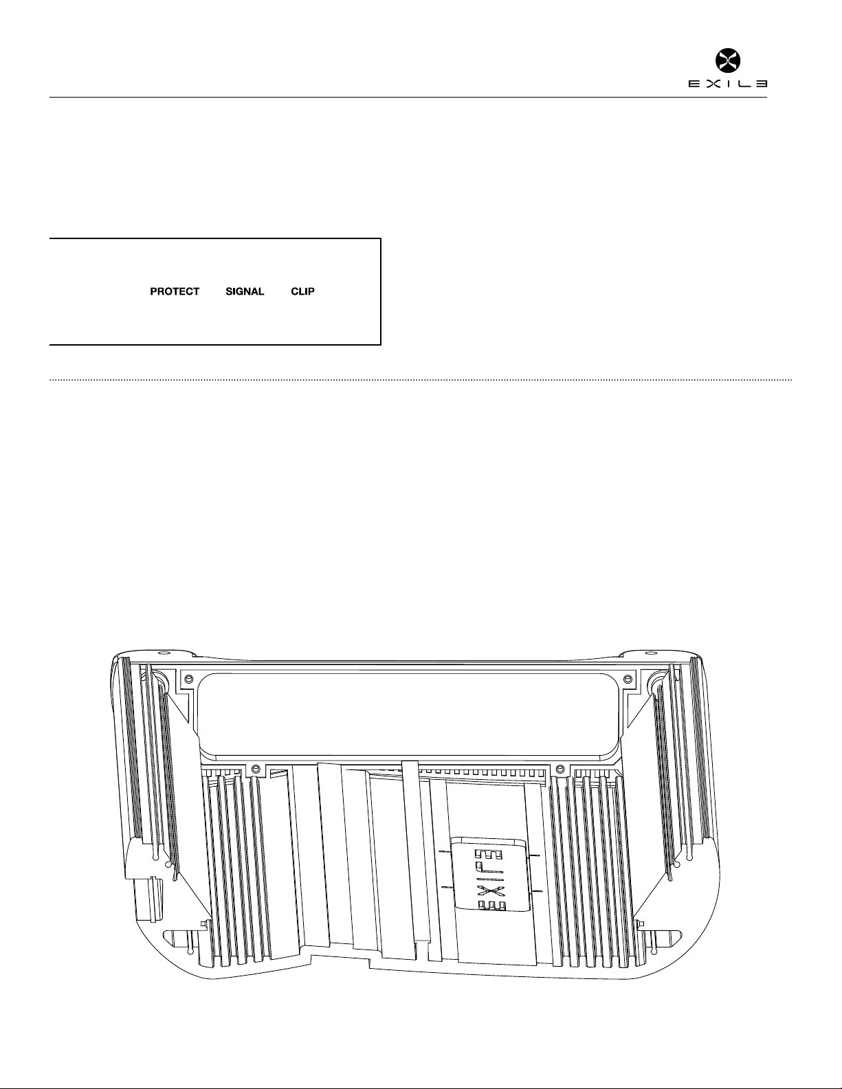
ISD MONITORING SYSTEM
Every amplier has a built in backlit display that shows the end user what is
happening inside the amplier. The ISD circuit is constantly monitoring the
signal, power output and protection conditions of the amplier.
ICE COOLING SYSTEM
High density aluminum heatsink, internal heatsink ns and vented die cast
endcaps are all carefully engineered to work in sync to keep the amplier
running cool and impossible to overheat.
EASY CLICK CROSSOVER SYSTEM
All crossover frequency potentiometers have 41 detents or “clicks” so the end
user can set the exact crossover frequency desired.
BLUE OR WHITE SELECTABLE LOGO COLOR
Flip the switch to choose blue or white logo color. When the amplier turns
on, the color will be the opposite for a few seconds as it slowly changes/fades
to the color selected by the switch.
HIGH LEVEL INPUT WITH SIGNAL SENSING AUTO TURN ON
Perfect to make factory or OEM system integration simple.

Amplier Owner’s Manual
© 2009 Exile Car Audio • www.exileaudio.com Amplifier Manual
MONOBLOCK SPECIFICATIONS
Frequency Response: ± 1dB from 20Hz to 300Hz
Signal to Noise Ratio: >90dB
Subsonic and Low Pass Crossovers: Linkwitz-Riley 24dB per octave
Low Pass Crossover Range: 30Hz to 300Hz
Subsonic Crossover Range: 10Hz to 55Hz
Bass Boost @ 45Hz: 0 to +18dB
Input Sensitivity: 200 millivolts to 8 volts
Lowest Recommend Load: 1 ohm
Typical Efciency: 85%
Damping Factor Greater than 200
TWO AND FOUR CHANNEL SPECIFICATIONS
Frequency Response: ± 1dB from 20Hz to 20kHz
Signal to Noise Ratio: >110dB
High and Low Pass Crossovers: 18dB per Octave
Low Pass Crossover Range: 40Hz to 400Hz
High Pass Crossover Range: 20Hz to 400Hz
Input Sensitivity: 200 millivolts to 8 volts
Lowest Recommend Load: 4 ohm Bridged or 2 ohm Stereo
Typical Efciency: 50%
Xi1500.1
Into 1 ohm 1500 x 1
Recommended Fuse Size: 100A
Power/Ground Wire Size: 4 Gauge
Dimensions: 16”L x 10”W x 2.45”H
Xi2500.1
Into 1 ohm 2500 x 1
Recommended Fuse Size: 200A
Power/Ground Wire Size: 1/0 Gauge
Dimensions: 18”L x 10”W x 2.45”H
Xi800.4
Into 4 ohm Stereo 125 x 4
Into 2 ohm Stereo 200 x 4
Into 4 ohm Bridge 400 x 2
Onboard Fuse Size: 30 amp x 2
Power Wire Fuse Size: 60 amp
Power/Ground Wire Size: 4 Gauge
Dimensions: 16”L x 10”W x 2.45”H
© 2009 Exile Car Audio • www.exileaudio.com Amplifier Manual
Amplier Owner’s Manual
INTEGRATED STATUS DISPLAY
In simple terms, ISD is the brain of your amplier and a smart one at that. In
tech terms, it’s a complex microprocessor circuit that constantly monitors the
signal, power output and protection conditions of the amplier. Each amplier
has a built in backlit display that shows the end user what is happening inside
the amplier.
ICE SYSTEM COOLING
Xi ampliers feature a sleek and clean cosmetic design, but underneath is the innovative ICE cooling system. ICE addresses the three key ways to keep ampliers cool:
Thermal Mass, Surface Area and Airow.
SIGNAL
Lights blue when the amplier provides signal to your speakers.
CLIP
Lights red when amplier reaches near maximum output and begins to
clip the audio signal. This is very powerful tool as it allows you to set up
the system for maximum output without the need of an expensive and
complicated O-scope. In normal operation the clip indicator should be
ashing often during dynamic parts of the music, this is normal. What is
not normal is if clip indicator is staying lit for long portions (more than 4 or
5 seconds) of time, then you need to reduce system volume or gain of the
amplier.
PROTECT
Lights red if there is a problem with the audio system. For example, speaker
wire gets pinched/shorted together, blown a voice coil or running too low of
an impedance, the ISD display will let you know.
THERMAL MASS
Xi ampliers are built like a brick house the heatsink is no different. It’s loaded with
10 grams per millimeter of Aluminum. Most other ampliers use 6 to 7 grams per
millimeter. This means the amplier has more thermal mass to soak up the energy/
heat created by your music than a standard amplier. Pickup a Xi amplier and you
will know it’s a serious amp.
SURFACE AREA
Eventually we need to get the energy/heat out of that heatsink and into the air.
What you can’t see is the internal extrusion of the heatsink is loaded with ns
that increase the surface area. These heatsink ns are also engineered to work in
conjunction with the diecast endcaps.
AIRFLOW
Exile engineers have integrating venting into the endcaps of the amplier. This
allows the amplier to exhaust the hot air out. Most ampliers are completely sealed
and this can build up unsafe heat levels inside the amplier that overtime can cause
failures.
Amplier Owner’s Manual
© 2009 Exile Car Audio • www.exileaudio.com Amplifier Manual
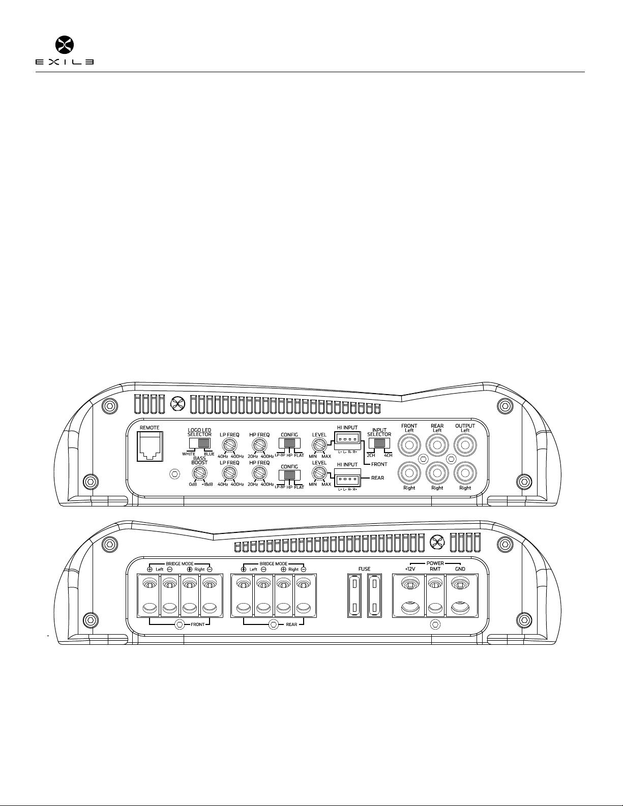
INPUT
Connect preamp signal cables from the head unit to these terminals.
OUTPUT
Provides a full range signal for an additional amplier. There is no signal loss if
using this output.
LP and HP CROSSOVER FREQUENCY
Controls the crossover point for the speaker outputs. This eliminates high
or low frequencies from reaching the speakers. The crossover frequency is
adjustable with a 18dB per octave slope. The potentiometers have 41 detents
see the chart to set the exact crossover frequency desired.
BASS BOOST
Variable bass boost from 0 to 18dB @ 45 Hz for rear channels only.
2ch/4ch MODE
2ch: Headunit has one pair of cables into front Input.
4ch: Headunit has two pairs of cables into front and rear inputs.
REMOTE BASS LEVEL CONTROL
This port is for connecting the optional remote level control (XRB1). This
allows up to 20dB of volume adjustment. This is not a bass boost, it controls
the level of the entire low pass signal of the rear channels.
GAIN
Used to reach maximum amplier power with a wide variety of headunits. The
amplier is more sensitive to input signals when set to .2 and less sensitive
when set to 8.
CROSSOVER SELECT SWITCH
HP: Sends a High Frequency signal to coaxial or component speakers.
FULL: Sends a Full Range signal to speakers.
LP/BP: Creates a Bandpass Frequency for subwoofers or midbasses. The LP
and HP are both activated, to turn HP (Subsonic Filter) off set it to 20Hz or Full
Counter Clockwise.
LOGO LED SWITCH
Used to select if the amplier logo color is white or blue. Please note when the
amplier turns on, the color will be the opposite for a few seconds then slowly
change to the color selected by the switch.
HI INPUT
Connect a factory system’s headunit or amplier outputs. Using the HI level
input the amplier will automatically turn on and off using the factory system’s
audio signal as a trigger.
12V+
This must be connected to the fused positive terminal (+12V) of the
car’s battery.
REMOTE
This must be connected to switched +12V, usually a trigger wire coming from
the head unit or ignition.
GND
This must be connected to the negative terminal of the car’s battery or bolted
to a clean, unpainted part of the chassis of the vehicle.
SPEAKER OUTPUTS
Used to connect the amplier to speakers. Use the left + and right - terminals
for bridged mode. Minimum speaker cable size is 16 gauge. Use 12 gauge for
bridged operation. Minimum impedance is 4 ohm bridged or 2 ohm stereo.
Xi800.4
4 Channel Power Ampliers
© 2009 Exile Car Audio • www.exileaudio.com Amplifier Manual
Amplier Owner’s Manual
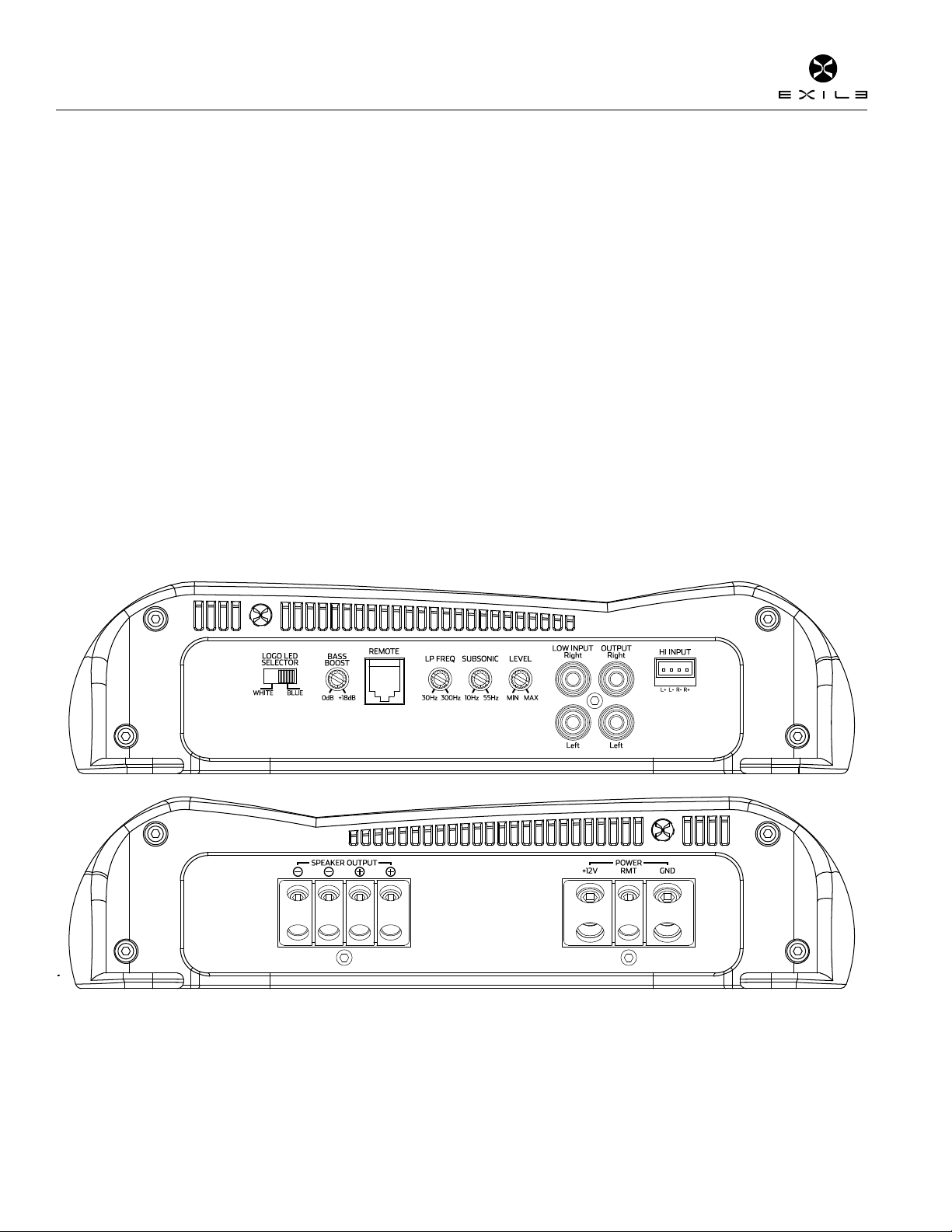
INPUT
Connect preamp signal cables from the head unit to these terminals.
OUTPUT
Provides a full range signal for an additional amplier. There is no signal loss if
using this output.
LP CROSSOVER FREQUENCY
Controls the lowpass crossover point for the speaker outputs. The crossover
is always on with a 24dB per octave slope. The potentiometers have 41
detents see the chart to set the exact crossover frequency desired.
BASS BOOST
Variable bass boost from 0 to 18dB @ 45 Hz.
REMOTE BASS LEVEL CONTROL
This port is for connecting the optional remote level control (XRB1). This
allows up to 20dB of volume adjustment. This is not a bass boost, it controls
the level of the low pass signal.
GAIN
Used to reach maximum amplier power with a wide variety of headunits.
The amplier is more sensitive to input signals when set to .2 and less
sensitive when set to 8.
SUBSONIC CROSSOVER FREQUENCY
Controls the highpass crossover point for the speaker outputs to eliminate
extreme low frequencies. The crossover is always on with a 24dB per octave
slope. The potentiometers have 41 detents see the chart to set the exact
crossover frequency desired.
LOGO LED SWITCH
Used to select if the amplier logo color is white or blue. Please note when
the amplier turns on, the color will be the opposite for a few seconds then
slowly change to the color selected by the switch.
HI INPUT
Connect a factory system’s headunit or amplier outputs. Using the HI
level input the amplier will automatically turn on and off using the factory
system’s audio signal as a trigger.
12V+
This must be connected to the fused positive terminal (+12V) of the car’s
battery.
REMOTE
This must be connected to switched +12V, usually a trigger wire coming from
the head unit or ignition.
GND
This must be connected to the negative terminal of the car’s battery or bolted
to a clean, unpainted part of the chassis of the vehicle.
(Note: Xi2500.1 uses a larger 1/0 terminal that is not shown above.)
SPEAKER OUTPUTS
Used to connect the amplier to speakers. The two + terminals are wired
together internally, the - terminals are also wired together internally. Minimum
speaker cable size is 12 gauge. Minimum impedance is 1 ohm.
Xi1500.1 - Xi2500.1
Monoblock Power Ampliers

Amplier Owner’s Manual
© 2009 Exile Car Audio • www.exileaudio.com Amplifier Manual
1. Install all system fuses.
2. Set the amplier’s input sensitivity
controls to their minimum positions (full
counterclockwise).
3. Set all amplier signal routing switches according to your system’s design.
4. Make preliminary adjustments to the crossover frequency, usually 80Hz is
good starting point for high and low pass. It may be necessary to ne tune the
crossover frequency later for the best overall
sound quality.
5. If using an XRB1 Remote Level Control, set it
to maximum (full clockwise).
6. Turn the headunit on with the volume set to
minimum.
7. Visually check the amplier’s has powered on by the logo lighting blue.
8. Check the condition of all other components to make sure they are powered
up.
9. Set the headunit’s tone controls, balance, and fader to the center (at)
position. Turn off any loudness or other signal processing features.
10. Set the volume control of the headunit for maximum undistorted output (on
most headunits this will be approximately 7/8 of maximum volume). Use a very
clear and dynamic recording.
11. Turn up the input sensitivity control until the speakers reach maximum
undistorted output.
12. Repeat input sensitivity adjustments for all other ampliers.
Note: The Exile amplier’s sensitivity, bass boost and XRB1
Level controls have no affect on the auxiliary outputs. An
amplier connected to the auxiliary outputs receives the same
signal level available to the Exile amplier’s inputs (unity gain).
13. Reduce the headunit’s volume to a comfortable level.
14. Listen to various musical selections to check overall system balance.
Compare front to rear, midbass to midrange, etc. If one speaker set is too loud
compared to another, then its level must be lowered to blend correctly with the
other speakers. The idea is to reference all speakers to the weakest set.
Note: For subwoofers controlled by an Exile XRB1 level control, keep the sensitivity
setting from step 11 or 12. Use the XRB1 to blend subwoofers with the rest of the
system. The correct subwoofer volume will change depending on road noise and
differences in recordings.
15. Fine tune crossover frequencies to achieve the smoothest possible blending of
each speaker set.
16. Adjust the Bass Equalization Controls on the amplier, headunit or processor
upstream if necessary to increase output.
Note: Use these controls sparingly. Every 3dB of boost requires double the power
at 45Hz. If your subwoofer system requires a lot of boost to sound good, there may
be a problem. Look for out-of-phase woofers, a leaking subwoofer box, or incorrect
box size.
17. With all levels set correctly, the system will reach overall maximum undistorted
output at the volume level set in step 10.
System Tuning

© 2009 Exile Car Audio • www.exileaudio.com Amplifier Manual
Amplier Owner’s Manual
Crossover Settings
CROSSOVER SETTINGS
Xi2500.1 - Xi1500.1
clicks Subsonic
(10~55hz)
LP
(30~300Hz)
Bass Boost
1 55 313 0.0
2 52 313 0.0
352 313 0.0
4 52 313 0.0
5 52 289 0.2
648 289 0.4
748 268 0.6
8 48 268 0.7
9 48 247 0.9
10 48 247 1.0
11 44 229 1.1
12 44 229 1.2
13 44 212 1.3
14 41 212 1.4
15 41 196 1.6
16 41 181 1.8
17 38 181 2.0
18 38 167 2.2
19 35 143 2.5
20 32 122 2.9
21 30 105 3.2
22 30 97 3.6
23 28 89 4.2
24 26 76 4.8
25 24 71 5.8
26 22 65 7.0
27 20 60 7.4
28 19 56 7.9
29 17 52 8.4
30 16 48 9.0
31 15 44 9.6
32 15 41 10.5
33 14 41 10.9
34 13 38 11.5
35 13 35 12.1
36 12 35 12.8
37 12 32 13.7
38 11 32 14.6
39 11 30 15.8
40 11 30 17.1
41 10 30 17.2
Xi800.4
clicks HP
(20~400hz)
LP
(40~400Hz)
Bass Boost
1434 434 0.1
2433 432 0.1
3 427 415 0.3
4416 385 0.6
5 404 361 0.9
6 392 343 1.3
7 382 325 1.7
8371 309 2.0
9362 295 2.4
10 353 283 2.7
11 336 275 3.1
12 301 229 3.5
13 276 204 4.0
14 266 187 4.5
15 253 169 5.0
16 234 156 5.7
17 219 144 6.3
18 204 134 7.2
19 192 125 7.9
20 181 117 8.7
21 170 110 9.5
22 161 94 10.5
23 153 77 11.7
24 127 65 13.1
25 109 57 13.5
26 96 96 13.8
27 86 86 14.3
28 77 77 14.8
29 70 70 15.3
30 65 65 15.8
31 60 60 16.1
32 56 56 16.5
33 52 52 16.8
34 49 49 17.1
35 46 46 17.5
36 43 43 17.9
37 41 41 18.3
38 39 39 18.7
39 38 38 19.0
40 38 38 19.0
41 38 38 19.0
EASY CLICK TECHNOLOGY
Easy Click technology is our commitment to making our products easy to use and ultra accurate for the professional or
DIY installer. All crossover frequency potentiometers have 41 detents or “clicks” so the end user can set the exact cross
over frequency desired. No more turning the potentiometer and guessing where your crossover points are. You get exact
control of your amplier’s output.

Amplier Owner’s Manual
© 2009 Exile Car Audio • www.exileaudio.com Amplifier Manual
LIMITED WARRANTY
Exile warrants this product to be free from defects in material and workmanship under normal use for a period of two years from date of original purchase when purchased from an Authorized Exile Dealer. If the product is labeled
B Stock/Refurbished and purchased from an Authorized Exile Dealer, it is warranted for 90 days from date of purchase, regardless of place of installation. Should service be necessary under this warranty for any reason due to
manufacturing defect or malfunction during the warranty period, Exile will replace or repair (at its discretion) the defective merchandise with equivalent merchandise at no charge. Warranty replacements on B-Stock merchandise may
have cosmetic scratches and blemishes. Discontinued products may be replaced with more current equivalent products. This warranty is valid only for the original purchaser and is not extended to owners of the product subsequent
to the original purchaser. Any applicable implied warranties are limited in duration to a period of the express warranty as provided herein beginning with the date of the original purchase at retail, and no warranties, whether express
or implied, shall apply to this product thereafter. Some states do not allow limitations on implied warranties, therefore these exclusions may not apply to you. This warranty gives you specic legal rights; however you may have other
rights that vary from state to state. This warranty is only valid within the USA, for warranties outside of the USA consult the appropriate international distributor.
EXILE CAR AUDIO
PORTLAND, OR USA
WWW.EXILECARAUDIO.COM
DESIGNED AND ENGINEERED IN THE USA
This manual suits for next models
2
Table of contents
Other Exile Car Amplifier manuals


