manuals.online logo
Brands
  1. Home
  2. •
  3. Brands
  4. •
  5. Exmark
  6. •
  7. Lawn Mower
  8. •
  9. Exmark Frontrunner Manual

Exmark Frontrunner Manual

109-4336 Rev. A
Page 1 of 4
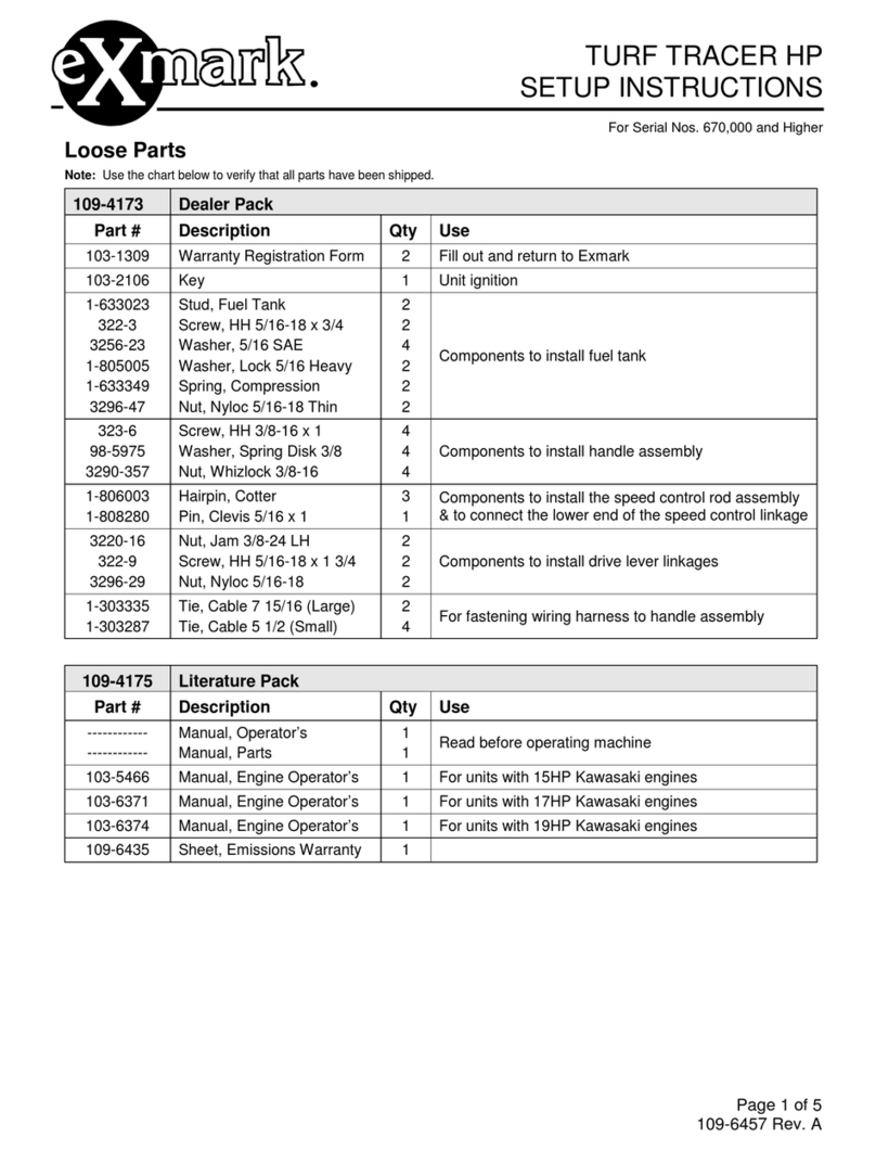
Loose Parts
Note: Use the chart below to verify that all parts have been shipped.
109-4333 Dealer Literature Pack
Part # Description Qty Use
323-8
98-5975
3290-357
283-69
1-323142
Cap Screw, Hex 3/8-16 x 1-1/2
Washer, Belleville
Nut, Hex Flange 3/8-16
Pin, Clevis 1/2 x 3-1/2
Nut, Push 1/2
8
8
8
2
2
Installing the Rollover Protection System (Roll Bar)
103-1309 Warranty Registration Form 1 Fill out and return to Exmark
103-2106
1-603511 Key, Exmark Ignition
Key, Standard Ignition 1
1 Unit ignition
109-4332 Literature Pack
Part # Description Qty Use
------------
------------
109-3498
Manual, Operator’s
Manual, Parts
DVD, Exmark Safety Video
1
1
1 Read and view before operating machine
110-3850 Manual, Engine Operator’s 1 For Units with Kubota Engines
Installing the Rollover Protection
System (Roll Bar)
For Units with the roll bar shipped loose:
1. Remove sides and top of crate from the base.
2. Remove roll bar components from the crate.
3. Remove roll bar tubes from sides of crate.
4. Locate the left and right lower roll bar tubes.
5. Align lower bar tubes along rear engine frame
6. Loosely install four 3/8-16 x 1-1/2 capscrews, four
spring disc washers, and four 3/16-18 whizlock
nuts to secure the rollbar to the frame of the unit.
(Fig. 1)
NOTE: Be sure the spring disk washer cone is
installed towards the head of the capscrew.
FIGURE 1
FRONTRUNNER™ DIESEL
SETUP INSTRUCTIONS
For Serial Nos. 670,000 and Highe
r
109-4336 Rev. A
Page 2 of 4
FIGURE 2
7. Locate the latch pin assemblies (pin and hairpin
connected with a lanyard).
8. Insert a 1/2 x 3-1/2 clevis pin into the bent tab
washer on the lanyard of each pin assembly. (See
Fig. 2)
NOTE: Make sure the bent tab in the washer is
towards the head of the clevis pin.
9. Lightly oil the inside surfaces of the ear-shaped
plates at the upper end of the lower roll bar tubes
10. Locate the upper u-shaped section of the roll bar.
Install the upper roll bar section using the two 1/2
x 3-1/2 clevis pins and two 1/2 push nuts. Make
sure upper roll bar can pivot freely.
NOTES:
Make sure the pin and push nuts are installed
with the push nut to the inside of the roll bar.
Make sure the tab on the lanyard washer is
installed as shown.
11. Raise the roll bar into the upright position and
secure with the latch pin assemblies on each side.
Install latch pin from outer surface of roll bar
assembly and secure with the hairpin to the inside.
12. Torque all lower roll bar hardware attached to the
machine frame to 30-35 ft-lbs. (41-47 N-m).
For Units with the roll bar shipped already
assembled to unit:
1. Remove top and sides from crate.
2. Loosen the mounting hardware that retains the
rollbar to each side of the unit. (Fig. 3)
3. Rotate the roll bar upwards and forward until the
remaining three holes in the mounting plate are
aligned with the holes in the unit frame.
4. Loosely install three 3/8-16 x 1-1/2” capscrews,
three spring disc washers, and three 3/16-18
whizlock nuts to secure the rollbar to the frame of
the unit. (Fig. 3)
NOTE: Be sure the spring disk washer cone is
installed towards the head of the capscrew.
5. Lightly oil the inside surfaces of the ear-shaped
plates at the upper end of the lower roll bar tubes.
6. Raise the roll bar into the upright position and
secure with the latch pin assemblies on each side.
Install latch pin from outer surface of roll bar
assembly and secure with the hairpin to the
inside.
7. Torque all lower roll bar hardware attached to the
machine frame to 30-35 ft-lbs. (41-47 N-m).
FIGURE 3
Installing Drive Wheels
1. Raise the front of the unit approximately 10-12”
and support it with jack stands or equivalent
support.
CAUTION
POTENTIAL HAZARD
♦Raising the front of the unit for assembly
relying solely on mechanical or hydraulic jacks
could be dangerous.
WHAT CAN HAPPEN
♦The mechanical or hydraulic jacks may not be
enough support or may malfunction allowing
the unit to fall, which could cause injury.
HOW TO AVOID THE HAZARD
♦DO NOT rely solely on mechanical or hydraulic
jacks for support. Use adequate jack stands or
equivalent support.
2. Remove the 1/2-20 drive wheel nuts (installed
on studs of drive motors) and retain for wheel
mounting. Remove and discard shipping
brackets mounted on wheel hubs.
109-4336 Rev. A
Page 3 of 4
3. Mount drive wheels with the valve stem to the
outside of the unit. Secure using four (4) 1/2-20
wheel nuts removed in step 2.
Torque to 95 ft-lbs (128 NxM).
Checking Tire Air Pressure
1. Check the air pressure in the drive tires.
Proper inflation for the drive tires is 9 psi (62
kPa). Adjust if necessary.
2. The mower deck casters and rear caster tires are
semi-pneumatic. No adjustment is necessary.
Servicing the Battery
The machine is shipped with a filled lead acid
battery.
1. Stop engine, wait for all moving parts to stop, and
remove key. Engage parking brake.
2. Tilt seat forward and raise hood to gain access to
the battery
3. Remove battery cover from machine.
DANGER
POTENTIAL HAZARD
♦Charging the battery may produce explosive
gasses
WHAT CAN HAPPEN
♦Battery gasses can explode causing serious
injury.
HOW TO AVOID THE HAZARD
♦Keep sparks, flames, or cigarettes away from
battery.
♦Ventilate when charging or using battery in an
enclosed space.
♦Make sure venting path of battery is always
open once battery is filled with acid.
2. Check the voltage of the battery with a digital
voltmeter. Locate the voltage reading of the battery
in the table below and charge the battery for the
recommended time interval to bring the charge up
to a full charge of 12.6 volts or greater.
IMPORTANT: Make sure the negative battery
cables are disconnected and the battery charger
used for charging the battery has an output of 16
volts and 7 amps or less to avoid damaging the
battery (see chart below for recommended charger
settings).
Voltage
Reading Percent
Charge
Maximum
Charger
Settings
Charging
Interval
12.6 or greater 100% 16 volts /
7 amps No Charging
Required
12.4 – 12.6 75 – 100% 16 volts /
7 amps 30 Minutes
12.2 – 12.4 50 – 75% 16 volts /
7 amps 1 Hour
12.0 – 12.2 25 – 50% 14.4 volts /
4 amps 2 Hours
11.7 – 12.0 0 – 25% 14.4 volts /
4 amps 3 Hours
11.7 or less 0% 14.4 volts /
2 amps 6 Hours
or More
CAUTION
POTENTIAL HAZARD
♦If the ignition is in the “ON” position there is
potential for sparks and engagement of
components.
WHAT CAN HAPPEN
♦Sparks could cause an explosion or moving
parts could accidentally engage causing
personal injury.
HOW TO AVOID THE HAZARD
♦Be sure ignition switch is in the “OFF” position
before charging the battery.
3. Connect the negative battery cables.
NOTE: If the positive cable is also
disconnected, connect the positive (red) cable
to the positive battery terminal first, then the
negative (black) cable to the negative battery
terminal. Slip insulator boot over the positive
terminal.
NOTE: If time does not permit charging the
battery, or if charging equipment is not available,
connect the negative battery cables and run the
vehicle continuously for 20 to 30 minutes to
sufficiently charge the battery.
Servicing the Engine
Engine is shipped with oil; check oil level and if
necessary fill to the appropriate level with oil as
specified in Engine Owner’s Manual.
Servicing the Hydraulic Oil
The machine is shipped with hydraulic oil in the
reservoir.
1. Run the machine for approximately 15 minutes
to allow any extra air to purge out of the
hydraulic system.
WARNING: Battery posts, terminals, and related
accessories contain lead compounds, chemicals
known to the State of California to cause cancer and
reproductive harm. Wash hands after handling.
109-4336 Rev. A
Page 4 of 4
2. Check hydraulic reservoir and if necessary fill the
reservoir to the appropriate level with Mobil 1
15W-50 synthetic motor oil.
3. Replace hydraulic reservoir cap and tighten until
snug. Do not overtighten.
NOTE: The baffle is labeled “HOT” and “COLD”.
The oil level varies with the temperature of the oil.
The “HOT” level shows the level of oil when it is at
225°F (107°C). The “COLD” level shows the level of
the oil when it is at 75°F (24°C). Fill to the
appropriate level depending upon the temperature of
the oil. For example: If the oil is about 150° F (65°C).
Fill to halfway between the “HOT” and “COLD” levels.
If the oil is at room temperature (about 75° F (24°C)),
fill only to the “COLD” level.
Checking Unit Tracking
Operate unit with both drive levers pushed to the full
forward position. Verify that the unit tracks in a straight
line. If not, adjust motion control linkages to correct
tracking as described in Operator’s Manual Adjustment
Section 4.2.5.
WARNING
POTENTIAL HAZARD
♦Operating a FrontRunner tractor without an
approved Exmark front mount attachment
increases the possibility of forward tip over.
WHAT CAN HAPPEN
♦Tip-over could cause serious injury or death.
HOW TO AVOID THE HAZARD
♦When operating a FrontRunner tractor without
an approved Exmark front mount attachment,
observe the following:
9Limit operation to minimum required to
install a different front mount attachment.
9Minimize speed and use extreme caution.
9Only operate on a flat level surface.
9Do not operate up or down a trailer ramp.
9Avoid sudden acceleration or deceleration.
Checking Safety Interlock System
1. Check starting circuit. The starter should crank
with the parking brake engaged, PTO
disengaged, the operator in the seat, and motion
control levers moved out in the neutral lock
position.
Disengage parking brake. The starter must not
crank.
Engage parking brake and engage PTO. The
starter must not crank.
Disengage parking brake and move each drive
lever in separately. Starter must not crank. Move
both drive levers in. Starter must not crank.
2. Check the kill circuits. Run engine at one-third
throttle, disengage parking brake and raise off of
seat (but do not get off of machine) engine must
stop after approx. 1/2 second has elapsed.
Run engine at one-third throttle, engage PTO
and raise off of seat (but do not get off of
machine) engine must stop after 1/2 second has
elapsed.
Run engine at one-third throttle, with brake
disengaged, move levers in and raise off seat
(but do not get off of machine) engine must stop
after 1/2 second has elapsed.
Run engine at one-third throttle, with brake
engaged, move left motion control lever in -
engine must stop.
Repeat moving the right lever in, then moving
both levers in - engine must stop whether
operator is on seat or not.
3. Check the PTO circuit: Open the folding deck
latches, disengage the park brake, move the
motion control levers in to neutral, and
disengage the PTO. Lower the deck until the
PTO switch arm is no longer depressing the
PTO “kill” switch. See Figure 4.
FIGURE 4
Run the engine at half throttle and pull up on the
PTO engagement switch.
The PTO must not engage.
NOTE: If machine does not pass any of these
tests, diagnose and repair any malfunctions
before final delivery to customer.
IMPORTANT: It is essential that operator safety
mechanisms be connected and in proper
operating condition prior to use for mowing.

Other manuals for Frontrunner

1

Other Exmark Lawn Mower manuals

Exmark ultra vac LAZER Z AS User manual

Exmark

Exmark ultra vac LAZER Z AS User manual

Exmark Lazer Z XP User manual

Exmark

Exmark Lazer Z XP User manual

Exmark Lazer Z CT User manual

Exmark

Exmark Lazer Z CT User manual

Exmark Lazer Z HP User manual

Exmark

Exmark Lazer Z HP User manual

Exmark RADIUS User manual

Exmark

Exmark RADIUS User manual

Exmark Metro 21 Series User manual

Exmark

Exmark Metro 21 Series User manual

Exmark FontRunner FR524 User manual

Exmark

Exmark FontRunner FR524 User manual

Exmark Lazer Z XS User manual

Exmark

Exmark Lazer Z XS User manual

Exmark Advantage Series 4500-466 User manual

Exmark

Exmark Advantage Series 4500-466 User manual

Exmark Lazer Z XS User manual

Exmark

Exmark Lazer Z XS User manual

Exmark Turf ranger User manual

Exmark

Exmark Turf ranger User manual

Exmark Metro HP MHP3614KA User manual

Exmark

Exmark Metro HP MHP3614KA User manual

Exmark Lazer Z Air-cooled series User manual

Exmark

Exmark Lazer Z Air-cooled series User manual

Exmark Turf tracer HP User manual

Exmark

Exmark Turf tracer HP User manual

Exmark METRO Manual

Exmark

Exmark METRO Manual

Exmark Turf tracer HP User manual

Exmark

Exmark Turf tracer HP User manual

Exmark Metro 26 User manual

Exmark

Exmark Metro 26 User manual

Exmark Metro HP User manual

Exmark

Exmark Metro HP User manual

Exmark METRO 408 User manual

Exmark

Exmark METRO 408 User manual

Exmark LAZER Z E-SERIES Operators User manual

Exmark

Exmark LAZER Z E-SERIES Operators User manual

Exmark Viking Hydro VH15KA362 User manual

Exmark

Exmark Viking Hydro VH15KA362 User manual

Exmark METRO User manual

Exmark

Exmark METRO User manual

Exmark Turf tracer HP User manual

Exmark

Exmark Turf tracer HP User manual

Exmark 4500-370 User manual

Exmark

Exmark 4500-370 User manual

Popular Lawn Mower manuals by other brands

EINHELL GC-PM 46 SM HW-E Li Original operating instructions

EINHELL

EINHELL GC-PM 46 SM HW-E Li Original operating instructions

Murray 42586X9A Instruction book

Murray

Murray 42586X9A Instruction book

AL-KO COMFORT 38.5 Li Original operating instructions

AL-KO

AL-KO COMFORT 38.5 Li Original operating instructions

MTD 122-336-120 owner's guide

MTD

MTD 122-336-120 owner's guide

Craftsman 25457 instruction manual

Craftsman

Craftsman 25457 instruction manual

LawnMaster GV1314 Operator's manual

LawnMaster

LawnMaster GV1314 Operator's manual

Husqvarna LB 553S Operator's manual

Husqvarna

Husqvarna LB 553S Operator's manual

CMi 468446 Original instructions

CMi

CMi 468446 Original instructions

Saber Edge LM-21ABS Operator's manual

Saber Edge

Saber Edge LM-21ABS Operator's manual

Toro ProLine 22040 Operator's manual

Toro

Toro ProLine 22040 Operator's manual

Craftsman 917.257573 owner's manual

Craftsman

Craftsman 917.257573 owner's manual

ST. SpA AM 98 Li 48 V1 Operator's manual

ST. SpA

ST. SpA AM 98 Li 48 V1 Operator's manual

Skil F0150713 Series Original instructions

Skil

Skil F0150713 Series Original instructions

Toro Reelmaster 5010- H Service manual

Toro

Toro Reelmaster 5010- H Service manual

Textron Ransomes Jacobsen HR3806 Series Maintenance and parts manual

Textron

Textron Ransomes Jacobsen HR3806 Series Maintenance and parts manual

MTD 660 Series owner's guide

MTD

MTD 660 Series owner's guide

Stiga XQ 130 HD V 302 Operator's manual

Stiga

Stiga XQ 130 HD V 302 Operator's manual

Rockwell RG8767 Safety and operating manual

Rockwell

Rockwell RG8767 Safety and operating manual

manuals.online logo
manuals.online logoBrands
  • About & Mission
  • Contact us
  • Privacy Policy
  • Terms and Conditions

Copyright 2025 Manuals.Online. All Rights Reserved.