Expand-it ABC-03 User manual

ABC-03
BRUSHCUTTER ATTACHMENT
OPERATOR’S MANUAL
ABC-03_Eng.qxp 5/19/2004 8:15 AM Page A1

Fig. 2Fig. 1
Fig. 4
Fig. 3
Fig. 6Fig. 5
1
6
7
8
1
9
5
4
2
3
10
2
13
11
14
12
17
1
15
16
ABC-03_Eng.qxp 5/19/2004 8:15 AM Page A2

Important!
It is essential that you read the instructions in this
manual before mounting and operating this machine.
Subject to technical modifications
ABC-03_Eng.qxp 5/19/2004 8:15 AM Page A3

WARNING
Read and understand all instructions.
Failure to follow all instructions listed below, may
result in electric shock, fire and/or serious
personal injury.
SAVE THESE INSTRUCTIONS.
GENERAL SAFETY RULES
■For safe operation, read and understand all
instructions before using the attachment. Follow all
safety instructions. Failure to follow all safety
instructions listed below, can result in serious
personal injury.
■Do not allow children or untrained individuals to use
this unit.
■Wear safety glasses or goggles that are marked to
comply with ANSI Z87.1 standards and hearing
protection when operating this unit.
■Wear heavy long pants, boots, and gloves. Do not
wear loose fitting clothing, short pants, jewelry of any
kind, or go barefoot.
■Secure long hair so it is above shoulder level to
prevent entanglement in any moving parts.
■Keep all bystanders, children, and pets at least
15 m away.
■Do not operate this unit when you are tired, ill,
or under the influence of alcohol, drugs, or medication.
■Do not operate in poor lighting.
■Keep firm footing and balance. Do not overreach.
Overreaching can result in loss of balance or
exposure to hot surfaces.
■Keep all parts of your body away from any moving part.
■Do not touch areas around the muffler or cylinder of
the power head, these parts get hot from operation.
Failure to do so could result in possible serious
personal injury.
■Always stop the engine and remove the spark plug
wire before making any adjustments or repairs except
for carburetor adjustments.
■Inspect unit before each use for loose fasteners,
damaged or missing parts. Correct before using the
attachment. Failure to do so can cause serious injury.
■Check for damaged parts. Before further use of the
appliance, any part that is damaged should be
carefully checked to determine that it will operate
properly and perform its intended function.
Check for alignment of moving parts, binding of
moving parts, breakage of parts, mounting, and any
other conditions that may affect its operation. A guard
or other part that is damaged should be properly
repaired or replaced by an authorized service center.
■Use only original manufacturer’s replacement parts.
Failure to do so, may cause poor performance,
possible injury, and will void your warranty.
■Do not, under any circumstance, use any attachment
or accessory on this product which was not provided
with the product or identified as appropriate for use
with this product in the Operator’s Manual.
1
English
ABC-03_Eng.qxp 5/19/2004 8:15 AM Page A4

DESCRIPTION
1. Attachment Shaft
2. Blade
3. Blade Guard
4. Gear Head
5. End Cap
6. Knob
7. Coupler
8. Guide Recess
9. Positioning Hole
10. Upper Flange Washer
11. Cupped Washer
12. Blade Nut
13. Spanner
14. Holding Pin
15. Hanger Cap
16. Button
17. Second Hole
ASSEMBLY
JOINING THE POWER HEAD TO THE
STRAIGHT SHAFT TRIMMER ATTACHMENT
(Fig. 1 & 2)
WARNING
Never attach or adjust any attachment while
power head is running. Failure to stop the engine
may cause serious personal injury.
The straight shaft trimmer attachment connects to the
power head by means of a coupler device.
■Loosen the knob (6) on the coupler (7) of the power
head shaft and remove the end cap (5) from the
attachment shaft.
■Push in the button located on the attachment shaft.
Align the button with the guide recess (8) on the
power head coupler and slide the two shafts together.
Rotate the attachment shaft until the button locks into
the positioning hole (9).
ASSEMBLY
2
English
SYMBOLS
Important: Some of the following symbols may be used on your tool. Please study them and learn their meaning.
Proper interpretation of these symbols will allow you to operate the tool better and more safely.
SYMBOLS NAME EXPLANATION
Safety Alert Symbol Indicates danger, warning or caution. it means attention!!!
Your safety is involved.
Read Your Operator's Manual Your manual contains special messages to bring attention to
potential safety concerns as well as operating and servicing
information. Please read all the information carefully to ensure
satification and safe use.
Wear eye and hearing protection Wear eye, and hearing protection when operating this
equipment.
Keep bystanders away Keep all bystanders at least 15m (50 ft) away.
Ricochet Danger of Ricochet.
Do not use toothed blade This unit is not intended for use with a toothed saw type blade.
ABC-03_Eng.qxp 5/19/2004 8:15 AM Page A5

ASSEMBLY
Note: If the button does not release completely in the
positioning hole, the shafts are not locked into place.
Slightly rotate from side to side until the button is
locked into place.
■Tighten the knob securely.
WARNING
Be certain the knob is fully tightened before
operating equipment; check it periodically for
tightness during use to avoid serious injury or
product damage.
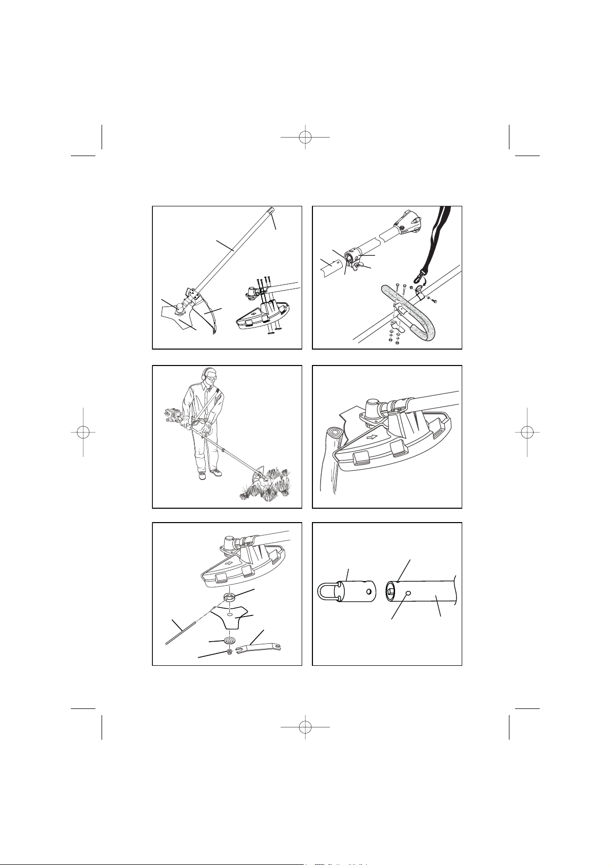
FRONT HANDLE (Fig. 2)
A barrier handle should be used for ensuring the best
control and maximising operator safety.
■Hold the top and bottom clamp snugly in position on
the shaft housing so that handle will be located to the
operator’s left.
■Insert the end of the handle between the clamps.
■Align the bolt holes and push the long bolt (1/4-20 x 1
1/2 in) through the handle side.
■Place short bolt (1/4-20 x 1 in) through opposite side
of clamp. Install flat washer, lock washers and hex
nuts to hold the assembly in place.
■After assembly is complete, adjust the position of the
handle for best balance and comfort.
■Tighten first the long bolt and then the short bolt.
■Connect the shoulder strap to the strap hanger adjust
to a comfortable position.
REMOVING THE ATTACHMENT FROM THE
POWER HEAD
For removing or changing the attachment:
■Loosen the knob.
■Push in the button and twist the shafts to remove and
separate ends.
OPERATION
OPERATING THE BRUSHCUTTER (Fig. 3 & 4)
Hold the brushcutter with the right hand on the trigger
handle and the left hand on the front handle. Keep a firm
grip with both hands while in operation. Brushcutter should
be held at a comfortable position with the trigger handle
about hip height. Maintain your grip and balance on
both feet. Position yourself so that you will not be drawn off
balance by the kick-back reaction of the cutting blade.
Exercise extreme caution when using the blade with
this unit. Blade thrust is the reaction which may occur
when the spinning blade contacts anything it cannot cut.
This contact may cause the blade to stop for an instant,
and suddenly "thrust" the unit away from the object that
was hit. This reaction can be violent enough to cause the
operator to lose control of the unit. Blade thrust may occur
without warning if the blade snags, stalls or binds. This is
more likely to occur in areas where it is difficult to see the
material being cut. For cutting ease and safety, approach
the weeds being cut from the right to the left. In the event
that an unexpected object or woody stock is encountered,
this could minimise the blade thrust reaction.
CUTTING TECHNIQUE - BLADE
WARNING
Extreme care must be taken when using blades
to ensure safe operation. Read the safety
information for safe operation using the blade,
refer to "Specific Safety Rules for Brushcutter
and Blade Use" earlier in this manual.
■Always hold brushcutter with both hands when
operating. Use a firm grip on both handles.
■Maintain your grip and balance on both feet. Position
yourself so that you will not be drawn off balance by
the kick-back reaction of the cutting blade.
■Inspect and clear the area of any hidden objects
such as glass, stones, concrete, fencing, wire, wood,
metal, etc.
■Never use blades near footpaths, fencing, posts,
buildings or other immovable objects.
■Never use a blade after hitting a hard object without
first inspecting it for damage. Do not use if any
damage is detected.
WARNING
Do not, under any circumstance, use any
attachment or accessory on this product which
was not provided with the product, or identified
as appropriate for use with this product in the
Operator's Manual.
MAINTENANCE
WARNING
Use only original manufacturer's replacement
parts, accessories and attachments. Failure to do
so may cause poor performance, possible injury
and may void your warranty.
3
English
ABC-03_Eng.qxp 5/19/2004 8:15 AM Page A6

English
4
MAINTENANCE
You may make adjustments and repairs described in the
maintenance section. For other repairs, have the unit
serviced by an authorized servicing dealer.
BLADE REPLACEMENT (Fig. 5)
■Stop the engine, place the holding pin (14) through
the slot in the upper flange washer (10) and the gear
head (4). Turn the blade nut clockwise to remove
the blade.
■Place the upper flange washer (10) over the gear
shaft with the hollow side towards the blade
guard.
MAINTENANCE
■Centre the new blade on the upper flange, making
sure the blade sits flat. Install the cupped washer (11)
with the raised center away from the blade. Install the
blade unit (12). The blade turns anticlockwise from
the operator's position.
■Place the holding pin through the slot in the upper
flange washer and the hole in the gear head. Using
the spanner (13), turn the blade nut anticlockwise.
■Tighten nut securely.
ATTACHING THE STORAGE HANGER (Fig. 6)
There are two ways to hang your attachment for storage.
■To use the hanger cap (15), push in the button (16)
and place the hanger cap over end of the attachment
shaft. Slightly rotate the cap from side to side until the
button locks into place.
■The secondary hole (17) in the attachment shaft can
be used for hanging purposes as well.
ABC-03_Eng.qxp 5/19/2004 8:15 AM Page A7

RYOBI TECHNOLOGIESAUSTRALIA PTY. LTD.
GUARANTEE
RYOBI TECHNOLOGIESAUSTRALIA PTY. LTD.
A.B.N. 98002 277 509
RYOBI NEW ZEALAND PTY. LTD.
AUCKLAND: 27 Clemow Drive, Mt Wellington, N.Z.
Contact during normalbusiness hours.
Subject to the guarantee condition below, thisRyobitool
(hereinafter called “the product”) isguaranteed byRyobi
(hereinafter called “the Company”) to be free from
defectsin material or workmanship for aperiod of 24
monthsfrom the date of originalpurchase covering
both partsand labour. Under the termsof this
guarantee, the repair or replacement of any part shall
be the opinion of the Company or itsauthorised agent.
Should service become necessary during the warranty
period, the owner should contact the RYOBI HELPLINE
1300 361 505 or contact the retailer from whom the
product was purchased.
In order to obtain guarantee service, the owner must
present the salesdocket and Guarantee Certificate
to confirm date of purchase. Thisproduct issold bythe
dealer or agent as principaland the dealer has no
authority from the Company to give any additional
guarantee on the Companyí sbehalf except as herein
containedorhereinreferredto.
Guarantee Conditions
Thisguarantee only appliesprovided that the Product
has been used in accordance with the manufacturer’s
recommendationsunder normaluseand reasonable
care (in the opinion of the Company) and such
guarantee doesnot cover damage, malfunction or
failure resulting from misuse, neglect, abuse, or used
for apurpose for which it was not designed or isnot
suited and no repairs,alterationsor modifications
have been attempted by other thananAuthorised
Service Agent. Thisguarantee will not apply if the tool is
damaged byaccident or if repairsarisefromnormal
wearand tear.
The Company acceptsno additionalliability pursuant to
thisguarantee for the costsof travelling or
transportation of the Product or partsto and from the
service dealer or agent - such costsare not included in
thisguarantee.
Certain legislation, including the Trade PracticesAct,
1974 (as amended) and other state and territoriallaws
give rightsto the buyer and imposeliability on the seller in
certain circumstances. Nothing herein shall have the effect
of excluding, restricting or modifying any condition,
guarantee, right or liability imposed, to the extent only
thatsuch exclusion, restriction or modification
would render any term herein void.
BRISBANE : All enquiriesTel : 1300 361 505
TOWNSVILLE: All enquiriesTel : 1 300 361 505
MELBOURNE:
HOBART: All enquiriesTel : 1300 361 505
ADELAIDE: All enquiriesTel : 1300 361 505
PERTH:
Address Of Dealer
Present ThisForm With YourPurchase Docket When Guarantee Service IsRequired.
Tel: - Fax: 1800 807 993- www.ryobi.com.au
Tel: (09) 5730230-FreeCall: 0800 279 624 - Fax: (09) 5730231 - www.ryobi.co.nz
For yourrecordand to assistinestablishing date of purchase(necessary for in-guarantee service)
pleasekeepyourpurchase docket and thisform completed with the following particulars.
ThisGuarantee Form Should Be Retained By The Customer At All Times
Date Model No SerialNo
SYDNEY: Building B, Rosehill Industrial Estate, 3-5 Shirley Street, Rosehill N.S.W. 2142
Contact during normal business hours.
1300 361 505
All enquiriesTel : 1300 361 505 33-35 Sorbonne Cres. Canning Vale, W.A. 6155
Tel : (08) 9455 7775
ABC-03_Eng.qxp 5/19/2004 8:15 AM Page A8
Table of contents