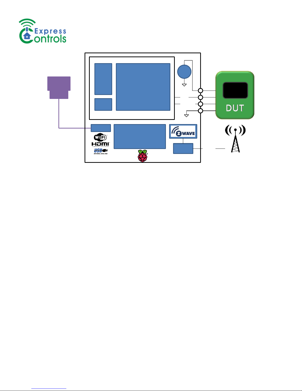
Express Controls ZWP500 User manual

ZWP500™
Z-Wave Production Programmer & Tester
www.ExpressControls.com
February 2018 Bringing the Internet of Things (IoT) to Life 1
ZWP500™
Z-Wave Production Programmer & Test Platform
•Sigma Designs Z-Wave SoCs/Module Programmer
•FLASH & NVM Programmer
•Production Test Platform
•Firmware Validation Platform
•Programmable in Python or C
•SmartStart enabled with QRCode label printing
•Fully Customizable
•Validation Services Available
Overview
The ZWP500 is a robust and reliable programmer for the
Sigma Designs 500 series of Z-Wave modules. A high-
speed SPI bus interface programs the Z-Wave module in
seconds. The ZWP500 is designed to operate on the
factory production floor with a fanless design and push-
button operation. The Raspberry Pi Linux computer is
augmented with a PSoC5 microcontroller to provide the
most accurate and fastest programming times possible.
A Z-Wave module with a programmable RF attenuator
allows the ZWP500 to fully test the RF parameters of the
target DUT. A 1ppm accurate crystal calibrates every
device for optimal RF performance.
The Python API enables customizable production
programming and testing. Program each NVR with a
unique AES-128 Security S2 DSK pin code or other
custom fields. Set the LOCK bits to prevent unauthorized
access to the firmware. Have your team develop the test
code or let the experts at Express Controls do it for you.
Features
Sigma Designs 500 Series FLASH Programmer
- Standard Sigma 12 pin programming header
oSPI interface for programming
oUART interface for debug
- NVR and external NVM programming & test
- 1ppm Crystal RF Calibration
- SmartStart QRCode generation & printing
- Fanless protective enclosure
Production Test Platform
- Customizable Python interface
- Scanner interface for serial number or DSK
- Label printer interface for DSK
- Camera interface for LCD screen testing
Z-Wave ZM5202 Module onboard
- Programmable RF Attenuator with SMA
Python API
- Customizable Programming API or GUI
- Sample test scripts for production testing
Programmable Power Supply
- +2.0V to +4.5V 300mA
- Resolution 100uV, 100 uAmps
Raspberry Pi based controller
- 1.2GHz Quad ARM CPU running Linux
- 1GB RAM - 8GB FLASH microSD
- Ethernet, WiFi, HDMI and USB connectivity
- Control locally or remotely via VNC
Ordering information:
ZWP500-AU –Programmer/Tester (908Mhz US)
ZWP500-AE –Programmer/Tester (868Mhz EU)
ZWP500-AH –Programmer/Tester (921Mhz ANZ)
ZWP500-DV –DevKit Interface Board
ZWP500-SVC - ZWP500 Services & Customization
VIO
PC
ENET
SPI
TIMING
ENGINE
ARM
CPU
UART
2.0V-4.5V
PSoC5
ZWP500
RASPBERRY Pi3
ENET Quad ARM A7
1GB /8GB MEMORY
Raspian LINUX
ZM5x0x
SPI
UART
Atten SMA

ZWP500™
Z-Wave Production Programmer & Tester
www.ExpressControls.com
February 2018 Bringing the Internet of Things (IoT) to Life 2
Table of Contents
Overview .................................................................................................................................................................................5
Quick Start Guide....................................................................................................................................................................5
Typical ZWP500 Setup ...........................................................................................................................................................6
SmartStart QRCode Label Printer.......................................................................................................................................6
Hardware Connections............................................................................................................................................................7
Z-Wave Programming Cable...............................................................................................................................................7
Z-Wave Antenna..................................................................................................................................................................7
Sigma DevKit Interface Board –ZWP500-DV ........................................................................................................................7
Raspberry Pi............................................................................................................................................................................9
PSoC PlugIn Board ...........................................................................................................................................................10
Serial Port..........................................................................................................................................................................10
USB Ports..........................................................................................................................................................................10
HDMI Port..........................................................................................................................................................................10
Ethernet Port......................................................................................................................................................................10
WiFi Access.......................................................................................................................................................................10
Desktop Sharing with VNC................................................................................................................................................10
Source Code Control of Scripts.........................................................................................................................................10
Sigma 500 Series RF Calibration..........................................................................................................................................11
Tx Calibration.....................................................................................................................................................................11
Crystal Calibration .............................................................................................................................................................11
Programming.........................................................................................................................................................................11
Non-Volatile Register (NVR) Fields...................................................................................................................................11
Override Value !.............................................................................................................................................................12
Incrementing Value +.....................................................................................................................................................12
Check Value ?................................................................................................................................................................12
Random Value # ............................................................................................................................................................12
Scanner Value $ ............................................................................................................................................................12
Sigma Security S2 DSK.................................................................................................................................................12
Lock Bits.........................................................................................................................................................................13
Example [nvr] Section....................................................................................................................................................13
Non-volatile Memory (NVM)..............................................................................................................................................13
VIO Voltage & Current.......................................................................................................................................................13
FLASH File Preparation.....................................................................................................................................................13
CRC32 Calculation ........................................................................................................................................................13
Programmer Example Python Application.........................................................................................................................14
Product Validation.................................................................................................................................................................14

ZWP500™
Z-Wave Production Programmer & Tester
www.ExpressControls.com
February 2018 Bringing the Internet of Things (IoT) to Life 3
Product Validation Example Python Application ...............................................................................................................14
Production Testing ................................................................................................................................................................14
Production Testing Example Python Application...............................................................................................................14
Manufacturing Data Logging .............................................................................................................................................14
ZWP500 Interface .................................................................................................................................................................14
PSoC Commands..............................................................................................................................................................14
AcquireDUT ...................................................................................................................................................................15
Calibrate.........................................................................................................................................................................15
FirmwareUpdate ............................................................................................................................................................15
FlashDownload ..............................................................................................................................................................16
FlashErase.....................................................................................................................................................................16
FlashWrite......................................................................................................................................................................16
FlashRead 0xxxxx:0yyyyy..............................................................................................................................................17
FlashVerify.....................................................................................................................................................................17
FlashCRC.......................................................................................................................................................................17
GPIOGet ........................................................................................................................................................................17
GPIOSet PS...................................................................................................................................................................17
Help................................................................................................................................................................................18
I2CGet AA LL.................................................................................................................................................................18
I2CProbe........................................................................................................................................................................18
I2CSend AA DD…[p] .....................................................................................................................................................18
LEDSet RGB..................................................................................................................................................................19
NVMGet SSSSSS:EEEEEE ..........................................................................................................................................19
NVMSet AAAAAA=DD...................................................................................................................................................19
NVRGet..........................................................................................................................................................................20
NVRSet AA=DD.............................................................................................................................................................20
ResetDUT [0] .................................................................................................................................................................21
RFAttenuatorSet DD......................................................................................................................................................21
UARTGet........................................................................................................................................................................21
UARTInit BB...................................................................................................................................................................21
UARTSend DD… ...........................................................................................................................................................22
VIOSet............................................................................................................................................................................22
VIOGet...........................................................................................................................................................................22
ZWaveGet [TT] ..............................................................................................................................................................22
ZWaveSend DD… .........................................................................................................................................................22
Troubleshooting ....................................................................................................................................................................23
Firmware Update...................................................................................................................................................................23
Terminal Window Settings with PuTTY.................................................................................................................................23
Python sample application....................................................................................................................................................24

ZWP500™
Z-Wave Production Programmer & Tester
www.ExpressControls.com
February 2018 Bringing the Internet of Things (IoT) to Life 4
References............................................................................................................................................................................24
Warrantee & Copyright..........................................................................................................................................................24
Document History..................................................................................................................................................................25

ZWP500™
Z-Wave Production Programmer & Tester
www.ExpressControls.com
February 2018 Bringing the Internet of Things (IoT) to Life 5
Overview
The ZWP500 is a production programmer for Z-Wave 500 series wireless RF modules. The ZWP500 programs Z-Wave
modules at their maximum programming speed bringing the typical programming time down under four seconds
compared to nearly 30 seconds with competing products. RF calibration is performed using the high accuracy 1ppm on-
board crystal. A fanless enclosure means the ZWP500 can be deployed on the factory floor without special packaging or
custom enclosures. The ZWP500 is a complete, high speed, robust production platform that can be customized to exactly
meet your requirements. Customization services are available from Express Controls team of experts.
In addition to being a fast production programmer, the ZWP500 is an ideal platform for testing Z-Wave devices. Product
testing on the factory floor to ensure every device is free of manufacturing defects requires an accurate, fast and robust
system. The ZWP500 utilizes the Linux based Raspberry Pi model 3 Quad Arm A7 processor which is then augmented
with the precise timing generators of a Cypress PSoC microcontroller and the RF capabilities of the on-board Z-Wave
module. A programmable power supply with current measurement capabilities enables rapid testing that the Device-
Under-Test (DUT) is free from gross production failures like power to ground shorts or missing power components. Either
Python or C programming languages can be used to develop a customized test program to fully verify every electronic
component of the DUT. Express Controls can write the test program for you or your team can develop it using the sample
code provided with the ZWP500 as a guide.
The ZWP500 is can be used for software validation to verify there are no bugs in each release of firmware. The full
power of high level programming languages like Python or C can be used to test every button press and Z-Wave
command class with each firmware revision. Push buttons can be activated with millisecond precision, DACs can
generate specific voltages or waveforms to trigger specific conditions, the power supply voltage can be varied to trigger
low-battery conditions as well as measure current to ensure the DUT battery lifetime will meet your specification. LCD
screens can be checked against reference images to verify every screen reacts properly to every button press. The power
of the RPi3 is completely at your disposal using the most advanced programming languages to fully test every aspect of
your product with every release.
Quick Start Guide
Unpack the ZWP500 which consists of the
following items:
1. ZWP500
2. Power Supply
The optional ZWP500-DV DevKit interface board
(shown here) is recommended for initial debug
and project development.
The following item must be supplied by you to
make a complete system:
1. Generic USB keyboard and mouse
2. Monitor with at least 1280x1024 resolution
and HDMI cable
3. Optional but recommended:
a. Sigma Designs Developers Board
ACC-ZDB5202-U2 (choose the one for your region)
Connect the ZWP500 to the keyboard, mouse and monitor. Connect the ribbon cable to the ZWP500-DV sample
developer kit interface board and plug the developer kit board into the interface board as shown. The developers kit board
is optional but is a good learning tool on how to use the ZWP500.
Connect the power supply into the ZWP500 and plug the power supply in. The ZWP500 should go thru the normal Linux
boot sequence and finally arrive at the ZWP500 desktop.

ZWP500™
Z-Wave Production Programmer & Tester
www.ExpressControls.com
February 2018 Bringing the Internet of Things (IoT) to Life 6
The icons on the left side of the
screen may be different.
Double click on the UserManual
icon to open the ZWP500 user
manual.
It is recommended to ALWAYS
double click on the SHUTDOWN
icon BEFORE powering the
ZWP500 off. This will cleanly
shut the file system down and
avoid corrupting the SD card of
the Raspberry Pi.
The PSOC icon opens a PuTTY
terminal window to communicate
directly with the PSoC. This can
be used to debug your own test
programs but is not used in normal operating modes.
Connect a Sigma Designs Development Board (not included) to the included DevKit interface board on J1. Click on the
SensorPIR icon and then press “?<enter>” to get a list of commands that can be run. See the Sigma DevKit Interface
section for more details.
Typical ZWP500 Setup
The ZWP500 does not come with all the items
required to build a complete programming and test
station. The ZWP500 is a complete Linux based
computer with a graphical user interface. Thus, a
keyboard, mouse and monitor are needed. The
RPi3 has an HDMI connector which is typically
connected to an inexpensive HDMI capable
monitor with at least 1280x800 resolution.
1910x1080p resolution is recommended. Any
generic keyboard and mouse will typically work.
They can be either wired for maximum reliability or
wireless for maximum flexibility.
A custom designed test jig is typically used to
connect to the ZWP500 and provide reliable and
easy connection to the DUT. Spring loaded pogo
posts are typically used to connect the 500 series
SPI bus to the ZWP500. Additional pins can
provide other capabilities to push button or
measure voltages. A 3D printed jig and clamp holds the DUT securely during programming and test.
SmartStart QRCode Label Printer
The ZWP500 has the ability to generate the required SmartStart QR Code labels for both the device and the package.
The QRCode requires customization to fit on the desired label but the sample SensorPIR project can be used as a guide.
Since each label is unique, the label MUST be immediately applied to the DUT to ensure the label matches values stored
within the DUT. Many types of printers are supported by the RPi including the popular Zebra printers. The Zebra GX430t

ZWP500™
Z-Wave Production Programmer & Tester
www.ExpressControls.com
February 2018 Bringing the Internet of Things (IoT) to Life 7
is recommended as it provides 300dpi resolution and yields a good quality image in permanent ink. The printer is plugged
into the USB port of the RPi and can be configured by using the browser to connect to the URL: localhost:631. More
information on working with printers can found on the Raspberry Pi or Linux web sites.
Hardware Connections
The ZWP500 uses the standard 12 pin Sigma Designs programming header. The Sigma ZDP03A has only a 10 pin
header and excludes the two UART pins but is otherwise pin compatible. Pins 2 and 5 are usually a no-connect on other
programmers but the ZWP500 uses these pins to connect to a DUT board with I2C GPIO expanders or other I2C devices
to enable complete control and measurement of the DUT. The cable should be less than 6 inches in length to ensure
reliable signal quality.
Z-Wave Programming Cable
Z-Wave Programming Cable - TOP view
VIO
1
2
I2C_SCL
NVM_CS_N
3
4
MOSI
I2C_SDA
5
6
MISO
GND
7
8
SCK
GND
9
10
RESET_N
RXD
11
12
TXD
Pin #
Signal Name
Description
1
VIO
Power for the DUT - programmable voltage from 2.0 to 4.5V at up to 300mA
2
I2C_SCL
Optional I2C SCL signal for controlling GPIO expanders/ADC/DACs on DUT test board
3
NVM_CS_N
Optional Chip Select signal to the Z-Wave module external NVM
4
MOSI
SPI MOSI signal
5
I2C_SDA
Optional I2C SDA signal
6
MISO
SPI MISO signal
7
GND
Ground (Vss) 0.0V
8
SCK
SPI Clock signal
9
GND
Ground (Vss) 0.0V
10
RESET_N
RESET_N pin of the Z-Wave module
11
RXD
Optional UART Receive Data (connect to the TXD of the Z-Wave module)
12
TXD
Optional UART Transmit Data (connect to RXD)
Z-Wave Antenna
An SMA connector on the side of the ZWP500 is typically connected to a 900MHz antenna to communicate with the DUT
over the Z-Wave radio. The SMA connector may be cabled to an RF shielded enclosure to limit the RF interference with
adjacent test stations or other Z-Wave networks.
Sigma DevKit Interface Board – ZWP500-DV

ZWP500™
Z-Wave Production Programmer & Tester
www.ExpressControls.com
February 2018 Bringing the Internet of Things (IoT) to Life 8
An interface board (ZWP500-DV DevKit) from the ZWP500 to
the Sigma ZDB5202 Developer Board is optional but highly
recommended for initial project development. Note that the
Sigma Developer Board is NOT included and must be
purchased separately (click on the links to purchase from
Digikey). The ZWP500-DV can be used to prototype the
programming and test environment of your product before the
hardware exists. The board can also be used as an example of
how to program and test a Z-Wave 500 series product using the
ZWP500. The SensorPIR project from the Sigma SDK is pre-
loaded on the ZWP500 and an icon to program and test it is on
the Desktop. Double click on the SensorPIR icon and a terminal
window comes up. Press “?<enter>” to get a list of commands
available by the programming and test program. The program is
written in Python and is in the /home/pi/examples/SensorPIR_test.py. Use the sample program to develop a customized
program/test suite or contract Express Controls to do it for you.
TBD –NOTE: Rev A ONLY supports the ZDB5202 Sigma Developer Board!!! The board is being updated to also support
the ZDB5101 and will be available soon.
Schematics for the ZWP500-DV DevKit board:

ZWP500™
Z-Wave Production Programmer & Tester
www.ExpressControls.com
February 2018 Bringing the Internet of Things (IoT) to Life 9
The DevKit board has two I2C GPIO expanders (PCAL9535A) at I2C address 20 and 21. These can be controlled using
the ZWP500 commands I2CSend and I2CGet. See the sample SensorPIR.py Python code for an example.
The PCAL chip command structure is the I2C Slave address, then a command byte which is a register address, then
optionally another data byte or two or perform an I2C read. See the PCAL9535A data sheet for more details.
•Command Byte definition:
•0x00 read port 0
•0x01 read port 1
•0x02 set the output value for port 0
•0x03 set the output value for port 1
•0x06 set the configuration for port 0, a 1 sets the pin to an input, 0 is an output
•0x07 set the configuration for port 1, a 1 sets the pin to an input, 0 is an output
Raspberry Pi
The brains of the ZWP500 are provided using the popular Raspberry Pi (RPi) embedded Linux computer. A plug-in board
is added to the RPi to provide high speed programming and measurement of the DUT. The RPi is a complete Linux
computer running the Raspian branch of the open source Linux operating system. A monitor and keyboard are typically

ZWP500™
Z-Wave Production Programmer & Tester
www.ExpressControls.com
February 2018 Bringing the Internet of Things (IoT) to Life 10
connected to the ZWP500 for full computer access (not included with the ZWP500). Most generic monitors with an HDMI
connection will work. Most generic wired or wireless USB keyboard and mouse will work with the RPi.
PSoC PlugIn Board
The RPi is augmented with a plug-in board that contains a Cypress PSoC System-On-Chip microprocessor. This
dedicated processor and its programmable hardware resources are used to program the DUT at the maximum speeds.
The PlugIn board also contains a ZM5202 Z-Wave chip and RF attenuators to enable complete testing of the DUT for
both functionality and RF performance. This board is integrated within the ZWP500 enclosure and should not be removed
or otherwise modified.
Serial Port
The PSoC PlugIn board is connected to the RPi via the 40 pin header on the RPi. The serial port on the header is the
primary communication method. The serial port /dev/ttyAMA0 operates at 921600 baud with 8 bits of data and 1 stop bit.
The UART connection is via the RPi expansion header on pins 8 and 10. The Raspberry Pi3 default has the “mini UART”
connected to the GPIOs and /dev/ttyAMA0 is connected to the on-board Bluetooth chip. The RPi has been configured to
swap the UARTs so that the /dev/ttyAMA0 UART is connected to the GPIOs (and thus the PSoC) and the mini UART is
connected to the Bluetooth chip which is normally not used but is still available.
USB Ports
Four USB 2.0 Type A connectors are present on the ZWP500. These USB ports support most generic USB devices like
keyboards, mouse, and memory sticks. The bar-code scanner and the label printer can be connected directly to these
USB ports.
HDMI Port
An HDMI port on the ZWP500 should be connected to a monitor to enable the user to interface with the software on the
ZWP500. The recommended resolution is 1280x1024 which is the default setting. The RPi supports many other
resolutions and most monitors will work. See the Raspberrypi.org site for details on configuring other resolutions.
Ethernet Port
An Ethernet RJ45 jack on the ZWP500 should be connected to a LAN which has access to the Internet. The ZWP500
requires a network connection to the internet to set the local time and date. Either a wired network connection or WiFi can
be used.
WiFi Access
The RPi3 has WiFi integrated onto the RPi3 board. WiFi can be configured using the network icon in the upper right
corner of the screen. See the Raspberrypi.org site for more details on configuring WiFi.
Desktop Sharing with VNC
The ZWP500 is configured with VNC for remote desktop access. Most VNC desktop applications will connect to the
ZWP500. The recommended application is TightVNC available from tightnvc.com. A password is required to log into the
ZWP500 with is “ExpressControls” (note the capitalization).
Source Code Control of Scripts
A common request is how and where to store the project specific custom coded scripts and how to deploy them across
multiple ZWP500 systems. The solution is to use git which is pre-installed on the RPi3. While any git server will work,
Express Controls recommends using BitBucket which provides a simple and free repository for small projects. Once the
account and a repository are created on BitBucket, you “clone” the repository onto the ZWP500. The table below gives a
few of the most commonly use git commands. See the online documentation of git for more details. Open a terminal

ZWP500™
Z-Wave Production Programmer & Tester
www.ExpressControls.com
February 2018 Bringing the Internet of Things (IoT) to Life 11
window and enter these commands. Do NOT put files in the examples, Desktop, or ZWP500 directory as these may
be overwritten when the ZWP500 code is updated.
Command
Description
git clone
"https://<username>@bitbucket.org/<acct>/<project>.git"
<local_directory_name>
Create a local repository on the ZWP500
•git status
Prints out which files in your local directory have
changed or need to be checked in
•git pull
Updates local directory/repository with the main branch
•git commit -a -m "comment"
Commits changed files TO YOUR LOCAL
REPOSITORY but not to BitBucket!
git push
Pushes your commits up to BitBucket - always do a
GIT PULL before committing/pushing
Sigma 500 Series RF Calibration
Each Sigma Designs chip or module must be calibrated to ensure optimal RF performance. See Sigma document
INS12524 for details on RF calibration. The ZM5202 and ZM5304 modules are both TX and Crystal calibrated at the
Sigma factory and do not need to be calibrated unless the NVR has been accidentally erased. The other Z-Wave modules
and chips all need some level of calibration. The ZWP500 contains a 1ppm accurate crystal and the necessary firmware
to perform both levels of RF calibration. The calibration is performed automatically and only if the NVR values are not
already programmed. After the calibration values are calculated, the NVR is updated with the new values and the CRC is
recalculated. The calibration process involves downloading a special calibration program into the DUT, then applying a
1ppm accurate 1MHz/256 clock onto the MISO pin. The calibration process takes 1.2 seconds plus the time to program
the DUT with the calibration program. Total time is about 3 seconds. Note that if performing crystal calibration it is strongly
recommended that the ZWP500 operate in a temperature and humidity controlled environment with an ambient
temperature of approximately 72F.
Tx Calibration
There are two TX calibration values stored in the NVR - TXCAL1 and TXCAL2. If CCAL is already calibrated this
calibration does not need as accurate of a clock but since the ZWP500 already has the 1ppm accurate clock, the
calibration is highly accurate.
Crystal Calibration
The crystal calibration value CCAL is also stored in NVR. Most of the modules have this value already programmed and
just need TxCal. Crystal calibration requires the 1ppm crystal which is part of the ZWP500.
Programming
Programming of Sigma Designs 500 series Z-Wave chips is described in the document INS11681. The ZWP500
implements the required algorithms for programming Z-Wave chips as quickly as possible using the dedicated PSoC
microprocessor. Firmware on the PSoC automatically identifies the DUT chip type, captures the NVR data, erases,
restores the NVR, programs flash and finally sets the Lock bits.
Non-Volatile Register (NVR) Fields
The values stored in the NVR are programmed using the ZWP500 and cannot be changed by the firmware on the DUT
itself. The NVR contains a number of fields required for Z-Wave operation including the calibration values, the module
type and the S2 security keys. Half of the NVR is available for user values and can be programmed with a variety of
values as described below. The NVR fields are described in Sigma document SDS12467. Typically, these values are
programmed with manufacturing data or with application specific data.

ZWP500™
Z-Wave Production Programmer & Tester
www.ExpressControls.com
February 2018 Bringing the Internet of Things (IoT) to Life 12
The values to be programmed in the NVR are defined in the <project>.ini file in the [nvr] section. All of the defined fields in
the Sigma NVR document SDS12467 are supported. The defined fields allow for fields that are more than one byte to be
programmed. The value to be programmed is a string with special characters on the end to perform specialized functions
as described in the following sections. Any byte in the NVR can be supported by editing the Python code. The PSoC
firmware supports all 256 bytes of the NVR. The PSoC treats the NVR as 256 bytes of memory. The Python code
performs all of the calculations for what values in the NVR need to be reprogrammed. By default, an NVR value defined in
the .ini file will be written to the NVR IF and ONLY IF the value in the DUT is 0xFF indicating the value has not been
previously programmed. The project.ini file is updated with the latest values for the NVR (primarily the next incremented
value) when the Python program exits.
Override Value !
If an exclamation point (!) is appended to the value then even if the NVR already contains a value other than 0xFF, the
value is programmed with the desired value. If there is no punctuation character at all for the NVR value, then if the
currently programmed value is all ones (0xFF) then the value in the .ini file will be written in. If the NVR already contains a
value it is not overwritten. The ! will override the current value and always write the NVR register with the desired value.
When a device is reprogrammed a second time, typically after being reworked to fix a manufacturing defect, typically the
settings in the NVR do NOT want to be overwritten. In some cases the values do want to be overridden and thus should
have the ! appended in the .ini file.
Incrementing Value +
Any NVR value can be an incrementing number by adding a + to the end of it. Each unit PROGRAMMED is assigned the
next value. If the NVR already has a value for this field (other than 0xFF), the value is not altered. The .ini file is updated
with the final valued used when the program is exited. This is most commonly used for UUID to program a serial number
for the unit. The value to be incremented is a 32 bit integer.
Check Value ?
If a question mark (?) is appended to the value then the NVR value is checked that it is already programmed with this
value. If the value is not already programmed with this value, then programming is halted and the operator is informed of
the failure. The most common NVR values to check is the REV field which is typically programmed by Sigma at the
factory. The value is either 0x01 or 0x02. If the value is 0xFF that would imply the module has not been properly initialized
and calibrated at the factory or that the NVR contents of this DUT has been lost. Either the module should be returned to
Sigma or it must be fully initialized and calibrated.
Random Value #
If a # is appended to a value then a fully random value is chosen for the next value. Most often this is used with the S2
security keys. Hardware is used to generate a truly random value and this is not a pseudo-random algorithm. The method
for computing a random value involves both hardware and software and a significant amount of communication and
computation. It is recommended to limit the use of the # to only the Security S2 keys to avoid processing delays during
programming.
Scanner Value $
If a $ is appended to a value then the attached bar code scanner is used to input the value. This is most commonly used
to match the value to a pre-printed bar code label on the device. There can be only one NVR value with this attribute in
the .ini file.
Sigma Security S2 DSK
The Security S2 keys are supported as required by REV=0x02 of the NVR. The Public key PUK and the private key PRK.
The PUK is required to be printed on the device and is used during the security negotiation immediately after inclusion.
The PRK is the matching private key. The PRK must be unique for every device and is typically generated using the
random value #. The PUK is computed based on the matching PRK. The PUK should be left blank in the .ini file.

ZWP500™
Z-Wave Production Programmer & Tester
www.ExpressControls.com
February 2018 Bringing the Internet of Things (IoT) to Life 13
Lock Bits
The lock bits can be set or cleared as desired using the EPx and RBAP identifiers. The lock bits EPx prevent the MCU
from erasing or writing to flash space. If using an external NVM then these bits should normally be cleared to 0 which will
lock the respective sector. If external NVM is not used, then parts of the FLASH are used by the application to store non-
volatile values and thus must not be locked. The MCU can always read FLASH, the lock bits only prevent it from
accidentally writing it in the event of a failure. The RBAP field is recommended to be set to 0xFE which enables the Read-
back protection which prevents hackers from reading the contents of FLASH via the SPI interface.
Example [nvr] Section
COMMENT - not included in the file
[NVR]
Start of the NVR section
rev = 02!
Force NVR rev to 02 since SmartStart is supported
pins = 01
ZM5202 swaps the pins, ZM5101 or others should be 0
nvmcs = 04
NVM Chip select pin –EX:P04=04
nvmt = 02
NVM Type
nvms = 0100
nvmp = 0100
sawc = xxxx?
sawb = xxxx?
nvr85 = 12
rbap = FE
Recommend RBAP = 0xFE which prevents reading the FLASH via SPI
ep = 0000000000000000
FLASH lock bits prevent the MCU from writing to FLASH
Non-volatile Memory (NVM)
Typically an external serial Non-Volatile Memory (NVM) is connected to the Z-Wave module to provide storage for the Z-
Wave network routing tables. The ZWP500 is able to inspect, erase and set values in the NVM using the NVMSet/Get
commands.
VIO Voltage & Current
The DUT is typically powered from the VIO pin of the ZWP500 cable. The voltage of VIO is programmable from +2.0V to
4.5V using the VIOSet command. The VIOGet command returns the instantaneous voltage at the VIO pin of the cable.
The current is also measured and returned with the VIOGet command. The programmable voltage allows the testing of
the battery level for devices that measure their battery level via the incoming power supply. The current measurement
allows the power to be profiled to ensure battery powered devices achieve the proper low-current sleeping state.
FLASH File Preparation
The file to be programmed into the DUT is the file directly from the Keil C51 compiler and passed thru the Sigma scripts to
add the CRC32. No additional processing is usually required. The RF Transmit Power (TXPOW) levels are typically
compiled into the source code or they can be modified in the hex file if necessary. The ZWP500 does not currently allow
overriding of the TXPOW values in the hex file.
The hex file is downloaded once into the ZWP500. Once it has been loaded it is stored internally and does not need to be
downloaded with each DUT making the programming process fast.
CRC32 Calculation
The hex file to be programmed into the DUT MUST have a CRC32 added to it. The Sigma SDK utilizes a program called
fixboot.exe to calculate the CRC. The CRC must already be present in the file and is checked with each DUT to ensure
programming is 100% accurate.

ZWP500™
Z-Wave Production Programmer & Tester
www.ExpressControls.com
February 2018 Bringing the Internet of Things (IoT) to Life 14
Programmer Example Python Application
The ZWP500 is primary a tool for programming the firmware into each 500 series DUT during production. The firmware
hex file is downloaded into the ZWP500 and then a simple short command is used to apply the proper VIO voltage for
programming, enter programming mode on the DUT, save the NVR values, erase FLASH, restore the NVR and update
with the desired values, transfer the firmware to the DUT and finally check the CRC of the firmware to verify the process is
100% accurate. If the NVR is identified as being uncalibrated, a calibration step can be performed using the 1ppm
accurate crystal of the ZWP500. See the SensorPIR example for more details.
Product Validation
Product Validation Example Python Application
TBD
Production Testing
Product testing is a short, focused test that identifies manufacturing defects in each DUT. Time is money on the
production floor so the test is usually a few tens of seconds long. The goal is to ensure any opens, shorts, missing or
defective components are identified so the DUT can be reworked. Ideally each customer receives a fully functional DUT
with a minimal number of returns.
Production Testing Example Python Application
The SensorPIR example code contains a short example of a test program where the VIO current to the DUT is measured
and several pins are toggled to verify it is defect free.
Manufacturing Data Logging
The SensorPIR example also logs a number of metrics into a comma separated value (.csv) file. Each DUT tested is
recorded in the file for later analysis and identification of areas of yield improvement.
ZWP500 Interface
The RPi communicates to the ZWP500 PSoC5 board via a UART which runs at 921600 baud. The following sections
detail the commands that can be sent to the PSoC5 and their responses. It is recommended to use the sample application
as a guide for the typical usage the low-level PSoC5 commands. The sample applications are in Python but any
programming language such as C can be used. All communication is in ASCII making it easier to debug.
PSoC Commands
The PSoC processor receives commands from the RPi over the UART. Each command is typically an ASCII string and
some optional data followed by a <CR>. See the section “Terminal Window Settings with PuTTY” for more details on how
to setup a terminal window to interact with the PSoC directly. Normally a Python or C program is used to communicate
with the PSoC. While the commands can be entered manually this is mostly just for debug purposes. The full command
name must be sent and the capitalization must exactly match as shown. The end of line character <LF> is ignored as are
spaces and the TAB character. Every command is echoed allowing the program to check that the command has been
properly received.
Every command responds with one of the following acknowledgements:
* = Command accepted
? = Command not understood - usually caused by an invalid command or corrupted data
# = Command discarded - usually because some other process is currently running
! = Command failed - additional data is typically provided with the reason for the failure
Many commands return additional data after the acknowledgement.

ZWP500™
Z-Wave Production Programmer & Tester
www.ExpressControls.com
February 2018 Bringing the Internet of Things (IoT) to Life 15
After a command is sent, the program must wait for the acknowledge and any expected return data. The PSoC may drop
commands if multiple commands are sent without waiting for the acknowledge.
AcquireDUT
The AcquireDUT command attempts to put the DUT into Z-Wave programming mode. If successful, the last four bytes of
signature of the chip is returned. The DUT must already be powered (VIOSet). The VIO will be measured and will return
an error if the voltage is below 2.0V.
Example: AcquireDUT
Returns:
*<cr>Signature= 7F1F0401<cr> if successful and the target device is a 500 series
!<cr>FAIL - VIO below 2.0V<cr> or other message indicating the failure. A signature of all FFs is a failure.
Calibrate
An RF calibration cycle is run on the DUT. This operation takes about 2 seconds to complete as the calibration program
has to be downloaded and then executed. The calibration values are NOT written to the NVR. The assumption is that a
programming cycle will immediately follow the calibration cycle and the new calibration values will be written to the NVR at
that time. The NVR is ERASED during the calibration process. It is REQUIRED to read the NVR prior to running a
calibration and to restore the NVR afterward. Do NOT run a calibration alone. The ZWP500 has a high precision crystal
and is able to accurately measure and set the CCAL value.
Example: Calibrate
Returns:
…..*<cr>CCAL=xx TXCAL1=yy TXCAL2=zz<cr>
Where xx, yy and zz are the hexadecimal values for the respective calibration values. The periods (.) indicate the
calibration program is being downloaded. The acknowledge (*) takes about 2 seconds before it is returned. An ! is
returned if there is a failure.
FirmwareUpdate
Download and update the PSoC firmware with the Intel hex file that is sent immediately after the command. Care must be
taken with this command as it is possible to “brick” the PSoC if there is a power failure during the process or if the data is
corrupted. When the PSoC is ready for each line of the hex file it will send an ACK (the character ‘$’). If the line of code
fails the checksum, then a NAK (‘~’) is sent and the line must be resent. The program sending the firmware MUST wait for
the ACK before sending the next line as the PSoC only has temporary storage for 1 line at a time. Every few lines there
will be a pause while the PSoC writes the data into FLASH. Note that the data is written directly into FLASH so if a failure
occurs it is likely unrecoverable and the unit will have to be reprogrammed at the factory.
Example:
FirmwareUpdate<cr>
<wait for the $ to arrive>
:400000000080002011000000A5490000A549000080B500AF024A034B1B68136004F0F6FCBC760040FA46004010B50
54C237833B9044B13B10448AFF300800123237010BD45
<wait for the $ to arrive then send each line of the intel hex file>
Repeat the two lines above for each line of the hex file. If a NAK is received, resend the line.
…
:00000001FF
The last line of the hex file is shown above and indicates that the download is complete.
*<cr>
Is the final indicator that the firmware download is complete and the PSoC will complete writing the data to FLASH and
then reboot. The normal boot messages will then be sent if the firmware is good.

ZWP500™
Z-Wave Production Programmer & Tester
www.ExpressControls.com
February 2018 Bringing the Internet of Things (IoT) to Life 16
FlashDownload
The FlashXXX commands are not normally needed by most users who can rely on the Python code included with the
ZWP500. The FlashXXX commands are documented here for users who want to fully customize the platform for their own
needs. Typically the sample Python code is used to provide higher level functions for programming.
Download the intel hex format file to be programmed into the DUT. The PSoC will send an ACK ($) character when it is
ready for each line of the hex file. The program sending the hex file MUST wait for the ACK before sending each line of
the file. If the checksum fails or there was a data corruption, a NAK (~) character is returned. The program should resend
the line if a NAK is received. The PSoC will pause every few lines while it writes the data to FLASH. Note that only Intel
Hex record type 04 is supported to set the upper address bits of the 128K byte image. The tools used to develop Z-Wave
code only use this record type.
Example:
#
Host
PSOC
Comment
1
FlashDownload<cr>
Initiate the command
2
FlashDownload<cr>
PSOC echoes the command
3
*<cr>
PSOC ACKs the command
4
WAIT up to 5s for the PSOC to setup the flash area
5
$<cr>
PSOC is ready for a line from the HEX file
A ~<cr> will be sent if the previous line checksum failed
6
send one line of HEX file
Host sends a line from the HEX file
7
WAIT up to 2s for the PSOC to process the line
8
Repeat steps 5 thru 7 for each line of the hex file
9
:00000001FF<cr>
Last line of HEX file
10
Wait up to 10s final check sum calculation
11
*<cr>
ACK download is complete and CRC is good.
!<cr> indicates a failure
12
Typically send a FlashCRC at this point to read the
calculated CRC value of the HEX file.
FlashErase
Erase the DUT FLASH. The NVR settings are retained but the rest of the DUT FLASH is reset to all ones. This command
is not normally needed as the FLASH is automatically erased during programming but is provided for completeness.
FlashWrite
Writes the downloaded Intel Hex file into the DUT. The DUT NVR must be read PRIOR to executing this command using
the NVRGet command. The DUT FLASH is erased, the NVR values are written, then the hex file is programmed into the
DUT. The CRC within the DUT is computed to ensure the hex file was programmed without error. If the CRC fails to
match then a NAK (!) is returned. This process takes several seconds to complete.
NOTE! It is REQUIRED to execute an NVRGet BEFORE issuing a FlashWrite! Each DUT typically has data in the NVR
pre-programmed by Sigma in the NVR and these values must be read before being erased and then restored. The NVR
values for TXCAL1 and TXCAL2 must be checked and if they are 0xFF then a calibration cycle must be run prior to
programming FLASH. Note that the TXCAL1/2 values must be written using NVRSet before programming FLASH.
Example:
NVRGet<cr> fetch the contents of the DUT NVR
Check the TXCAL1/2 NVR values, if 0xFF, then run Calibrate and update the TXCAL1/2 values
NVRSet …<cr> Adjust any NVR values required (this may require multiple NVRSet commands)
FlashWrite<cr> Erase FLASH, Write NVR, write the hex file to FLASH, check the CRC
Returns:
*<cr> If the hex file was programmed into the DUT without error
!<cr> if the programming failed. An error code may also be included in the message.

ZWP500™
Z-Wave Production Programmer & Tester
www.ExpressControls.com
February 2018 Bringing the Internet of Things (IoT) to Life 17
FlashRead 0xxxxx:0yyyyy
Read the DUT FLASH contents from address xxxxx to address yyyyy and return the data. This command is typically used
to debug a failure to program FLASH. Note that the xxxxx and yyyyy addresses must be exactly 5 hexadecimal characters
and be preceded with a 0.
Example: Read the entire contents of the DUT FLASH (128K bytes)
FlashRead 000000:01FFFF<cr>
@00000=000102030405060708090a0b0c0d0e0f000102030405060708090a0b0c0d0e0f<cr>
…
*<cr>
Thirty Two (32) bytes are returned on each line.
FlashVerify
Verify the contents of the DUT FLASH match the downloaded hex file. The first 100 mismatching bytes are returned if
any. Typically the FlashCRC command can be used to verify the contents of FLASH much more quickly than using this
command. This command is typically used to debug a failure of some kind and is not used in normal programming of the
DUT due to the several seconds this command takes to run.
Example:
FlashVerify<cr>
Returns:
*<cr> If the DUT FLASH matches the downloaded hex file
@xxxxx=yy!=zz If the DUT FLASH does NOT match the hex file, up to 100 lines like this are returned
The DUT FLASH at address xxxxx is yy but the expected value is zz.
FlashCRC
Returns the four byte CRC in the downloaded hex file, the computed CRC and the DUT CRC if the DUT is acquired.
Typically this command is used to ensure the proper hex file is downloaded into the ZWP500.
Example:
FlashCRC<cr>
Returns:
!<cr>FlashCRC=xxxxxxxx CalcCRC=yyyyyyyy DUTCRC=zzzzzzzz<cr>
Where xxxxxxxx is the CRC in the downloaded hex file if one has been downloaded, yyyyyyyy is the calculated CRC
based on the downloaded hex file which should be the same as the FlashCRC. If a DUT is connected, powered and
acquired, then zzzzzzzz is returned which is the CRC programmed into the DUT flash.
GPIOGet
Returns the binary voltage state of all 12 pins of the programming cable. The value is either 1 or 0 as the voltage is either
positive or ground. The tristate state cannot be detected and the pin is either 0 or 1 depending on the voltage.
Example:
GPIOGet<cr>
Returns:
*<cr>GPIO=1 2 3 4 5 6 7 8 9 A B C
Where the value of the respective pin is printed as either 0 or 1. Note that pins 7 and 9 are always 0 since these pins are
GROUND. Note that there is an extra space between pins 4 and 5 and 8 and 9 to make the pin state more readable.
GPIOSet PS
Set the desired pin (P) of the Z-Wave programming cable to the desired state (S). The variable P is one of the following
[2-6,8,A,B,C] where A is pin 10, B is pin 11 and C is pin 12 (hexadecimal). Pin 1 is the VIO pin and is controlled using the
VIOSet command. Pins 7 and 9 are GROUND. Valid values for the state S are [0,1, Z] where Z is tristate. Most of the pins

ZWP500™
Z-Wave Production Programmer & Tester
www.ExpressControls.com
February 2018 Bringing the Internet of Things (IoT) to Life 18
of the programming cable are dedicated to the SPI bus used for programming the DUT and accessing the external NVM.
Pins 2, 5, 11 and 12 however are generally available for use and can be used to sense or drive test points on the DUT. If
more than 4 pins are needed, an I2C bus GPIO expander can be placed on the DUT test board. Digital to analog
converters, ADCs, temperature sensors and any I2C device can be placed on the DUT test board and pins 2 and 5 can be
used to communicate with those devices. See the I2CSend and I2CGet commands for more details. Be aware that the
DUT has to be powered for the GPIO pins to be driven to the proper voltage. The programming cable pins are powered
with the VIO power supply. Use the GPIOGet command to verify the pin is set to the desired level.
Example: Set pin 2 to tristate
GPIOSet 2Z<cr>
Returns:
*<cr>
?<cr> is returned if an invalid pin number or value is sent
Help
The Help command returns a brief description of the most commonly used commands. The firmware version is returned
as part of the data. A ? will also return the list of commands.
I2CGet AA LL
Send an I2C read command to I2C slave address AA (bits [7:1]) and read LL bytes of data. LL must be greater than 0. If
the command completes properly, the data is returned as !<cr>I2CGet= 01 02 03 …<cr>. If the address or length fields
are not hexadecimal then a ? is returned. If the slave NAKs the address byte then a ! is returned. An I2C STOP condition
is always performed at the end of the command.
Example:
I2CGet 21 03
Returns:
!<cr>
I2CGet= 01 02 03
This example sends an I2C read command to slave address 0x21 (the first byte of the command is 0x43). If the slave
ACKs the write, then the three data bytes are read from the device and returned. All values are hexadecimal.
I2CProbe
Configures pins 2 and 5 of the Z-Wave programming cable for I2C and then tests all 127 I2C addresses [1-127] and
returns the address of any I2C devices that acknowledge the address byte. This command is used to find the I2C
addresses of devices on the DUT test board. The address returned are bits [7:1] of the I2C address byte. If no I2C
devices acknowledge, then a NAK (!) is returned. If one of the I2C pins is stuck either high or low a NAK is returned along
with a message indicating which pin is stuck.
Example:
I2CProbe<cr>
Returns:
*<cr>
ACK@ 21 22<cr> If there is an I2C device at 0x21 (0100_001Rb) and 0x22 (0100_010Rb).
Address 0x21 maps to a slave address write byte of 0x42. The address is in bits [7:1] and bit 0 is the READ/WRITE bit.
I2CSend AA DD…[p]
Send an I2C write command to I2C slave address AA (bits [7:1]) with the data DD and optionally NOT send an I2C STOP
if the character ‘p’ is at the end of the command. All values are in hexadecimal. The data is optional and may contain up to
32 bytes of data. If the I2C bus is in the idle state, then the command is initiated with an I2C START. If the previous
command was not completed with an I2C STOP, then an I2C ReSTART initiates this command. The character ‘p’ at the
end of the command allows commands to be linked together. Typically this is used to set the address pointer within the

ZWP500™
Z-Wave Production Programmer & Tester
www.ExpressControls.com
February 2018 Bringing the Internet of Things (IoT) to Life 19
I2C device which is then followed by an I2CGet. The I2C data to be sent is dependent on the capabilities of the I2C
device. The data rate is just under 100Kbps which ensures that virtually any I2C device can be supported. If the address
or data fields are not hexadecimal a ‘?’ is returned. If the slave NAKs any byte of the command, a ‘!’ is returned. If the
command completed without error a ‘*’ is returned.
Example:
I2CSend 21 01 02 03 p
Returns:
*<cr>
This command will send to I2C slave address 0x21 (the first byte is 0x42), the data 0x01, 0x02, 0x03 and then will NOT
issue a STOP at the end of the command.
LEDSet RGB
Set the color of the LED on the ZWP500 enclosure to one of the eight possible colors. Each of the three LEDs (Red,
Green, Blue) can be turned ON with a 1 or off with a 0. The RGB value must be three digits of either 0 or 1. Invalid values
will return a ?. The LED on the ZWP500 can be used to indicate to the operator that the DUT is passed (green) or failed
(red) or that the programming/testing is underway (any of the other colors).
000=OFF
001=BLUE
010=GREEN
100=RED
111=WHITE
Example:
LEDSet 100 Turns on only the RED LED
Returns:
*<cr>
NVMGet SSSSSS:EEEEEE
Most Z-Wave devices utilize an external Non-Volatile Memory to store the Z-Wave routing tables, application specific
variables and an Over-The-Air firmware image. The NVM is most often an Adesto AT25PExx which is fully supported by
the ZWP500. The NVM chip select signal must be connected to the Z-Wave programming cable pin 3 to enable access by
the ZWP500. The NVMGet command reads the NVM starting at address SSSSSS and ending at address EEEEEE. Both
fields must be six hexadecimal characters long and separated by a colon (:) character. The data is returned 16 bytes per
line with the address at the beginning of the line. The NVM manufacturer strings can be returned with the command
NVMGet M. Getting the manufacturing strings is a quick command to verify the NVM is functional. If S or E are not
hexadecimal a ? is returned. If there is an error then a ! is returned.
Example:
NVMGet M<cr>
Returns:
*<cr>
NVM MFG=20 80 12 This is the manufacturing string for the Micron M25PE20.
Example: Get the first 16 bytes of the NVM
NVMGet 000000:00000F
Returns:
*<cr>
@000000= 00 01 02 03 04 05 06 07 08 09 0A 0B 0C 0D 0E 0F<cr>
NVMSet AAAAAA=DD
The NVMSet command programs the NVM address AAAAAA with the value DD. The address and data fields are in
hexadecimal. All six characters of the address field must be present. If the fields are not hexadecimal a ? is returned. After

ZWP500™
Z-Wave Production Programmer & Tester
www.ExpressControls.com
February 2018 Bringing the Internet of Things (IoT) to Life 20
setting the NVM to a new value it is recommended to do an NVMGet to verify the data was properly set. The entire NVM
can be reset to all ones with the command “NVMSet R”.
Example:
NVMSet R The entire NVM is bulk erased to all ones
Returns:
*<cr>
Example:
NVMSet 000008=29 Set address 0x000008 to 0x29
Returns:
*<cr>
NVRGet
The Non-Volatile Registers (NVR) flash page of the Z-Wave module is not the same as the NVM. The NVR data is
programmed at the factory and contains data specific to the hardware. The data cannot be changed by the MCU or by a
firmware download over the air (OTA). Details of the fields in the NVR are specified in Sigma document SDS12467 “500
Series Z-Wave Chip NVR Flash Page Contents”. The NVR version 2 is supported which contains the DSK for Security S2.
The upper half of the NVR is available for the application.
The NVRGet command returns all 256 bytes of the NVR. If the NVR was returned by the DUT then a *<cr> is returned. If
the NVR failed to be read (typically because it is not powered) then a !<cr> is returned. The data is returned in 16 rows of
16 bytes using the format <cr>@AA= 00 01 02 03 04 05 06 07 08 09 0A 0B 0C 0D 0E 0F where AA is the address for the
row. Execute the command AcquireDUT before sending the NVRGet.
Example:
NVRGet<cr>
Returns:
*<cr>
@00= FF FF FF FF FF FF FF FF FF FF FF FF FF FF FF FF
@10= 01 09 01 FF 0D E8 8C 1B 00 FF FF FF FF FF FF FF
@20= FF FF FF FF FF FF FF FF FF FF FF FF FF FF FF FF
@30= FF FF FF FF FF FF FF FF FF FF FF FF FF FF FF FF
@40= FF FF FF FF FF FF FF FF FF FF FF FF FF FF FF FF
@50= FF FF FF FF FF FF FF FF FF FF FF FF FF FF FF FF
@60= FF FF FF FF FF FF FF FF FF FF FF FF FF FF FF FF
@70= FF FF FF FF FF FF FF FF FF FF FF FF FF FF 34 E3
@80= FF FF FF FF FF FF FF FF FF FF FF FF FF FF FF FF
@90= FF FF FF FF FF FF FF FF FF FF FF FF FF FF FF FF
@A0= FF FF FF FF FF FF FF FF FF FF FF FF FF FF FF FF
@B0= FF FF FF FF FF FF FF FF FF FF FF FF FF FF FF FF
@C0= FF FF FF FF FF FF FF FF FF FF FF FF FF FF FF FF
@D0= FF FF FF FF FF FF FF FF FF FF FF FF FF FF FF FF
@E0= FF FF FF FF FF FF FF FF FF FF FF FF FF FF FF FF
@F0= FF FF FF FF FF FF FF FF FF FF FF FF FF FF FF FF
NVRSet AA=DD
Set the NVR address AA to the value DD. This command sets the NVR value of the DUT to be programmed to this value.
The NVR is not written immediately. The NVR of the DUT is written as part of programming flash. The CRC16 field of the
NVR (address 0x7E and 0x7F) is automatically calculated when the NVR is written to the DUT.
ALWAYS execute an NVRGet BEFORE issuing any NVRSet commands! NVR values are unique to each DUT and are
pre-programmed by Sigma Designs at the factory. The pre-programmed data must be restored prior to programming
flash.
Example:
NVRGet<cr> ALWAYS Read the NVR to capture the data pre-programmed by Sigma
Table of contents