Express ENCORE EXE3 User manual

I.B. 1660
Rev AB 7/17
IMPORTANT
Read and understand your user’s manual before installing, operating or servicing this
product.
DO NOT DESTROY THIS BOOK
Model: EXE3
Express
®
EnCore™Battery Charger
Owner’s Manual
To automatically be connected to your closest Service Center, call us toll-free at:
1-800-ENERSYS (1-800-363-7797)

Express®EnCore™ Owner’s Manual I.B. 1660
1
TABLE OF CONTENTS
Important Safety Instructions ..................... 2
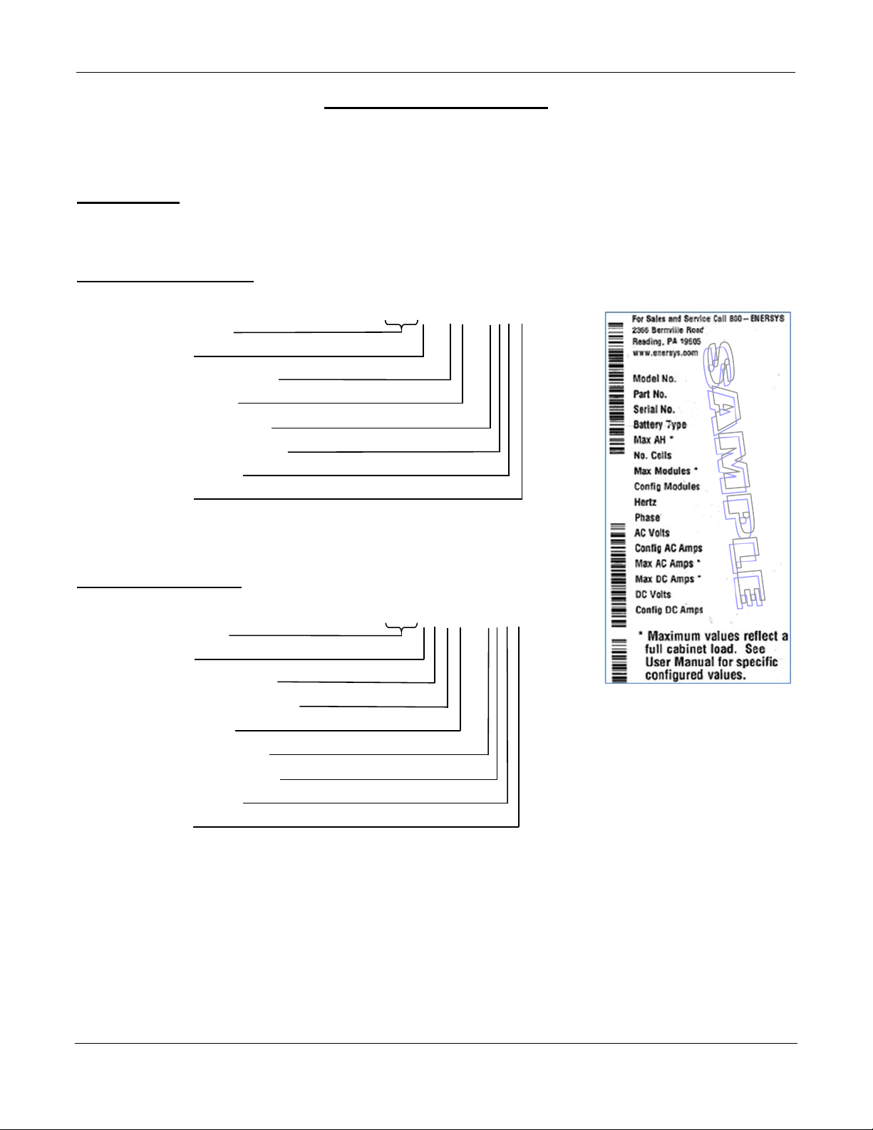
Technical Information ................................. 3
Part Number ............................................ 3
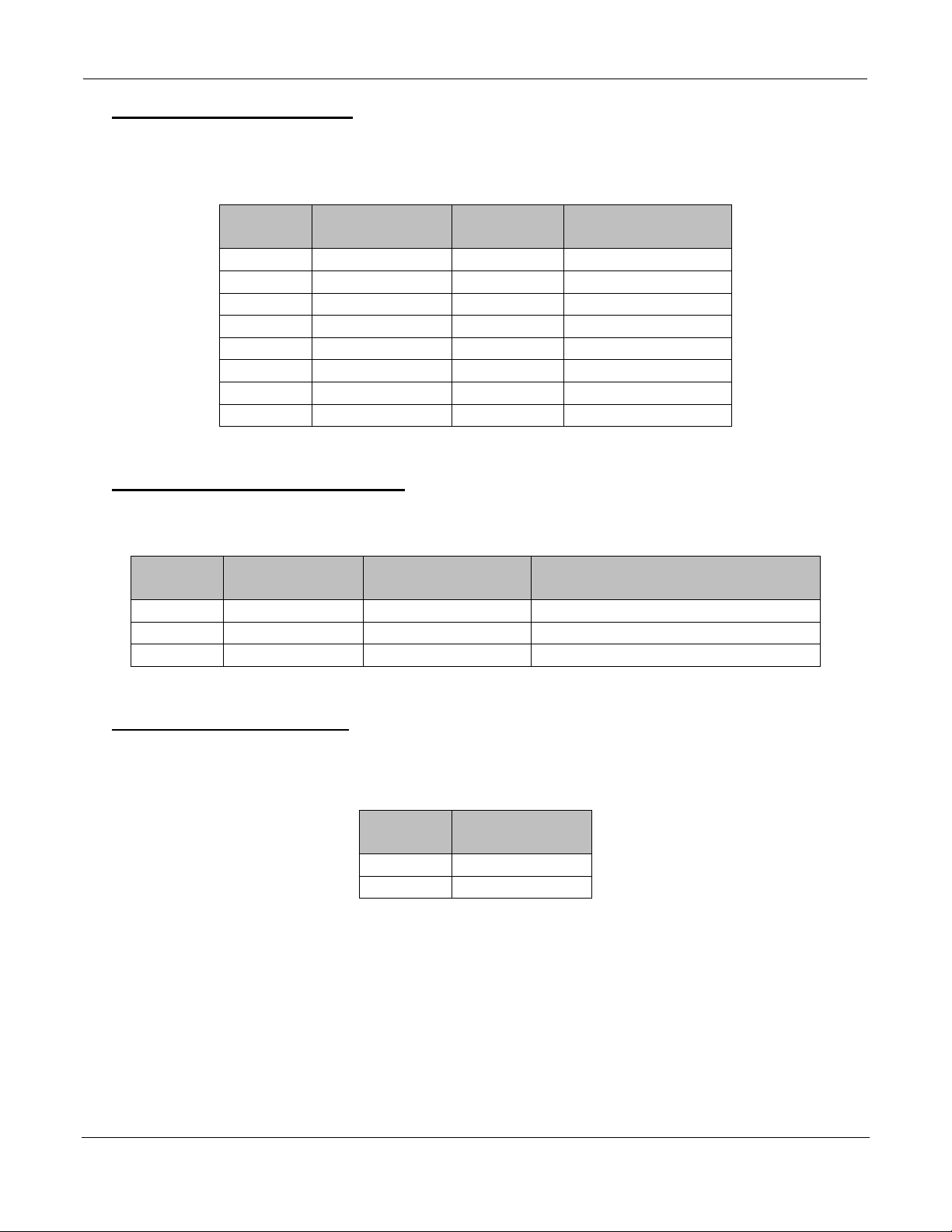
Output Power Letter Codes .............. 4
Cabinet Size/Gauge Letter Codes .... 4
DC Voltage Number Codes .............. 4
AC Line Voltage Letter Codes .......... 5
Charge Profile Letter Codes ............. 5
Specialty Charger Option List ........... 5
Serial Number ......................................... 5
Battery Type ............................................ 6
Max AH .................................................... 6
No. Cells .................................................. 6
Max Modules ........................................... 6
Config Modules ....................................... 6
Hertz ........................................................ 6
Phase ...................................................... 6
AC Volts .................................................. 6
Config AC Amps ...................................... 6
Max AC Amps ......................................... 6
Max DC Amps ......................................... 6
DC Volts .................................................. 6
Config DC Amps ..................................... 7
CEC ......................................................... 7
cULus ...................................................... 7
Installation .................................................... 8
Location ................................................... 8
Cabinet Mounting .................................... 8
Electrical Connections ............................. 8
Connecting Input Power .......................... 8
AC Disconnect ........................................ 9
Plug Polarity ............................................ 9
Grounding the Charger ........................... 9
Description of Operation ............................ 10
General .................................................... 10
Starting the Charge Cycle ....................... 10
Charging Current ..................................... 10
AC Power Fail ......................................... 10
Series Charging ...................................... 10
Glossary ....................................................... 11
Wi-iQ® Device .......................................... 11
Charging Profile ...................................... 11
Cold Storage Profile ................................ 11
Equalization Charging ............................. 11
Gel-Bloc Profile ....................................... 11
IONIC™ Profile ....................................... 11
VRLA Profile ............................................ 11
Opportunity Profile .................................. 11
Operation ............................................ 11
Daily Charge ....................................... 12
Block Out Time ........................................ 12
Refresh Charging .................................... 12
Abbreviations and Acronyms ..................... 13
Operating Instructions ................................ 14
Control Panel ............................................... 15
Menu Access ................................................ 16
Main Menu Display .................................. 16
Main Menu ............................................... 16
Logs .............................................................. 17
Memorizations Display Screen ................ 17
Displaying a Charge Cycle ...................... 17
Memorization Data .................................. 17
Status ............................................................ 18
Status Screen .......................................... 18
Charger ......................................................... 19
Information .............................................. 19
Charger Information Display ................... 19
USB ............................................................... 20
Update Software ...................................... 20
Settings ......................................................... 20
Parameters .............................................. 20
Date/Time ................................................ 20
Language ................................................ 20
Region ..................................................... 20
Display ..................................................... 20
Screen Saver .................................... 20
Delay ................................................. 20
Themes ............................................. 21
Daylight Savings ...................................... 22
Password ...................................................... 2 2
Charging the Battery ................................... 23
Charger Idle Display ................................ 23
Starting a Charge Cycle .......................... 24
Delayed Start ........................................... 24
Count Down Display ................................ 24
Charger Display ....................................... 25
End of Charge Display ............................ 26
End of Charge without Equalization ........ 26
End of Charge with Equalization ............. 26
Manual Equalization Start ................. 26
Automatic Equalization Start ............. 27
Fault Codes .................................................. 28
Fault Display ............................................ 28
Maintenance and Service ............................ 30
Mounting Dimensions ................................. 31
3.5 kW 4 Bay Cabinet
Mounting Dimensions .............................. 31
3.5 kW 6 Bay Cabinet Mounting
Dimensions .............................................. 32
3.5 kW 8 Bay Cabinet Mounting
Dimensions .............................................. 33
Technical Specifications ............................. 34
3.5 kW Standard Technical
Specifications .......................................... 34
Maintenance Log .......................................... 38

Express®EnCore™ Owner’s Manual I.B. 1660
2
IMPORTANT SAFETY INSTRUCTIONS
WARNING: THE SHIPPING PALLET MUST BE REMOVED FOR PROPER AND SAFE OPERATION.
1. This manual contains important safety and operating instructions. Before using the battery charger, read all
instructions, cautions and warnings on the battery charger, the battery and the product using the battery.
2. This charger has been designed to only charge lead acid batteries. Read and understand all setup and
operating instructions before using the battery charger to prevent damage to the battery and to the charger.
3. Do not touch non-insulated parts of the output connector or the battery terminals to prevent electrical shock.
4. During charge, batteries produce hydrogen gas which can explode if ignited. Never smoke, use an open flame
or create sparks in the vicinity of the battery. Ventilate well when the battery is in an enclosed space.
5. Do not connect or disconnect the battery plug while the charger is on. Doing so will cause arcing and burning
of the connector resulting in charger damage or battery explosion.
6. Lead-acid batteries contain sulfuric acid which causes burns. Do not get in eyes, on skin or on clothing. In
cases of contact with eyes, flush immediately with clean water for 15 minutes. Seek medical attention
immediately.
7. Only factory qualified personnel can service this equipment. De-energize all AC and DC power connections
before servicing the charger.
8. The charger is not for outdoor use.
9. Do not expose the charger to moisture. Operating conditions should be 32º to 113º F (0º to 45º C); 0 to 70%
relative humidity.
10. Do not operate the charger if it has been dropped, received a sharp hit or otherwise damaged in any way.
11. For continued protection and to reduce the risk of fire, install chargers on a floor of non-combustible material
such as stone, brick or grounded metal.

Express
®
EnCore™ Owner’s Manual I.B. 1660
3
TECHNICAL INFORMATION
The nameplate, located on the outside of the charger, should be used to check this application
before installation.
Part Number
This is the charger part number and specifies the characteristics of this particular charger and
for this reason it is required in any discussion or correspondence regarding this unit.
Single Display Cabinet:
EXE3 - GN - 4YF *
Model Type
Phase
Power Level Top
Cabinet Size
DC Voltage Code
Input Voltage Code
Charge Profile
Options
Dual Display Cabinet:
EXE3GHR - 4YF *
Model Type
Phase
Power Level Top
Power Level Bottom
Cabinet Size
DC Voltage Code
Input Voltage Code
Charge Profile
Options

Express®EnCore™ Owner’s Manual I.B. 1660
4
Output Power Letter Codes
The following table describes the letter codes to be used in charger part numbers to indicate
the Output Power of the charger.
Letter
Code
Output Power
(kW)
Number
Modules
Module Power
(kW)
G 3.5 1 3.5
H 7.0 2 3.5
I 10.5 3 3.5
J 14.0 4 3.5
K 17.5 5 3.5
L 21.0 6 3.5
M 24.5 7 3.5
N 28.0 8 3.5
Cabinet Size/Gauge Letter Codes
The following table describes the letter codes to be used in charger part numbers to indicate
the number of slots and size of the DC cables.
Letter
Code
Module
Positions
Standard Cable
Gauge Comments
N 4 3/0 Four slot, 3.5 kW cabinet
P 6 3/0 Six slot, 3.5 kW cabinet
R 8 3/0 Eight slot, 3.5 kW cabinet
DC Voltage Number Codes
The following table describes the number codes to be used in charger part numbers to
indicate the DC output voltage(s) of the charger.
Number
Code
Output
Voltage(s)
4 24/36/48
5 72/80

Express®EnCore™ Owner’s Manual I.B. 1660
5
AC Line Voltage Letter Codes
The following table describes the letter codes to be used in charger part numbers to indicate
the AC line voltage(s) and AC line frequency at which the charger can be operated.
Letter
Code
Voltage(s)
(volts rms)
Line
Frequency
(Hertz)
Comments
C 600 50/60 600 VAC only
Y 480 50/60 480 VAC
*For 480VAC chargers with line voltage of 400VAC, see specifications starting on page 34.
Charge Profile Letter Codes
The following table describes the letter codes to be used in charger part numbers to indicate
the Charging profile of the charger.
Letter
Code Profile
C Cold Storage
I IONIC™
O Opportunity
F Fast
Specialty Charger Options List
Suffix Description
C6 6 Ft of AC Cord
C10 10 Ft AC Cord
C12 12 Ft of AC Cord
L10 10 Ft of DC cable
L13 13 Ft of DC cable
L15 15 Ft of DC cable
L18 18 Ft of DC cable
L20 20 Ft of DC cable
L25 25 Ft of DC cable
L30 30 Ft of DC cable
Serial Number
This number indicates complete information about the specific charger. It must be supplied with
the part number on any correspondence or discussion regarding this charger.

Express®EnCore™ Owner’s Manual I.B. 1660
6
Battery Type
The chemical content construction of the battery this unit is designed to charge is given in this
part of the nameplate. (L-A = Lead Acid)
Max AH
This is the maximum amp-hours capacity of this cabinet.
No. Cells
This is the number of battery cells this unit will charge. This number must match exactly with
any battery connected to the charger output.
Max Modules
This is the maximum number of modules the cabinet can hold.
WARNING: THE NUMBER OF MODULES MUST MATCH THE NUMBER OF “CONFIG
MODULES” ON THE NAMEPLATE. DO NOT ADD MORE MODULES IN THE FIELD.
CONSULT THE MANUFACTURER IF MORE MODULES ARE NEEDED.
Config Modules
This is the number of modules for which this cabinet is configured.
Hertz
This gives the frequency in cycles per second of the AC input voltage. Under no conditions
operate the charger at a different frequency or from a generator with unstable frequency.
Phase
Number "3" indicates a Three Phase Charger.
AC Volts
This is the nominal voltage for which this charger is rated. The charger will only operate on this
voltage.
Config AC Amps
This is the AC Amps for which this charger is configured.
Max AC Amps
This is the maximum AC Amps for which this cabinet is rated.
Max DC Amps
This is the maximum output DC Amps for which this charger is rated .
DC Volts
This gives the nominal DC output voltage of the charger.

Express
®
EnCore™ Owner’s Manual I.B. 1660
7
Config DC Amps
This is the output DC Amps this charger is configured for to deliver to a battery.
CEC
This logo is applied to chargers that are certified with the California Energy Commission in
compliance with Appliance Efficiency Regulations:
cULus
This logo is applied to chargers that have been tested to applicable standards and requirements
by Underwriters Laboratories (UL) and the Canadian Standards
Association (CSA):

Express
®
EnCore™ Owner’s Manual I.B. 1660
8
INSTALLATION
WARNING: THE SHIPPING PALLET MUST BE REMOVED FOR PROPER AND SAFE
OPERATION.
Location
For maximum safe operation, choose a location which is free of excess moisture, dust,
combustible material and corrosive fumes. Also, avoid locations where temperatures are high
or where liquids will drip on the charger. Do not obstruct the ventilation openings. Follow charger
warning label when mounting on or over a combustible surface. The recommended charger
mounting should be at least 28 inches above the battery.
Cabinet Mounting
The charger must be mounted on a wall, stand, shelf or floor in a vertical position. 8 bay chargers
may only be mounted to the floor or an appropriate stand. The minimum distance between two
chargers must be 12 inches.
The charger will be installed with four 5/16 inch bolts or with the bracket supplied. See the
Mounting Dimensions section at the end of this manual for proper bolt pattern. Charger should
be permanently fastened in place.
For shelf mounting, part number 159-6LA22723 is required – two per charger.
Electrical Connections
To prevent failure of the charger, make sure it is connected to the correct line voltage.
Follow your local and National Electric Code (NEC) in making these connections.
WARNING: MAKE SURE THE POWER TO THE CHARGER IS OFF AND THE BATTERY
IS DISCONNECTED BEFORE CONNECTING THE INPUT POWER TO THE TERMINALS
OF THE CHARGER.
Connecting Input Power
Connect the input power to the appropriate terminals and apply appropriate torque as follow:
Phase Power (kW) Cabinet (Bay) Terminals Torque (in-lbs)
3 3.5 4 and 6 L1 L2 L3 15
3 3.5 8 L1 L2 L3 25
Connect ground wire to terminal marked with either of the two symbols below and apply same
torque value per table above:
NOTE: Ambient temperature at all levels cannot exceed 113° F (45° C).

Express
®
EnCore™ Owner’s Manual I.B. 1660
9
AC Disconnect
The user must provide suitable branch circuit protection and a disconnect method from the AC
power supply to the charger to allow for safe servicing.
Plug Polarity
The charging cable is connected to the DC output of the charger with the positive lead marked
RED. The output polarity of the charger must be strictly observed when connecting to the battery
(read warning above). Improper connection may open the DC fuse and/or damage the charger.
Grounding the Charger
DANGER: FAILURE TO GROUND THE CHARGER COULD LEAD TO FATAL ELECTRIC
SHOCK. Follow National Electric Code for ground wire sizing.
Connect a grounding conductor to the Ground lug provided on the horizontal support panel.
This lug is marked with either of these symbols:

Express®EnCore™ Owner’s Manual I.B. 1660
10
DESCRIPTION OF OPERATION
General
Express®EnCore™ chargers are microprocessor-controlled. When using the Fast Profile, the
battery voltage and capacity is communicated to the charger by the Wi-iQ® device. The charging
coefficient is maintained absolutely on all types of batteries. Express EnCore chargers adapt to
the battery’s capacity and its discharge level.
Express EnCore chargers can easily be set to charge flooded batteries used in Cold or freezer
storage applications, IONIC™, Fast or Opportunity profiles. This battery charger is also designed
to charge flooded lead acid storage batteries within the range of the cell and ampere-hour rating
as marked on the nameplate.
Starting the Charge Cycle
When a battery is connected to the charger, the control board senses the voltage and after a
short delay, the charger starts charging the battery.
Charging Current
Charging current is determined by the battery voltage and state of the charge condition. Charging
current declines automatically as battery voltage rises during the charge. As the battery charges,
the graphical display will output various charge parameters including the percentage of battery
capacity.
AC Power Fail
If the AC power fails with a battery connected to the charger during a charge cycle, the charger
will reset and start a new charge cycle when power is restored. All charger settings as well as
the time and date are preserved.
Series Charging
In series charging, the voltages of both batteries add up and must match charger’s nameplate
DC Volts rating. The charger’s amp-hour rating must be equal to each battery’s ampere-hour
rating. Charge cycle will not start unless both batteries are connected.

Express®EnCore™ Owner’s Manual I.B. 1660
11
GLOSSARY
Wi-iQ® Device
This unit, permanently mounted on the battery, ensures that certain battery parameters can be
sent to the charger for the purposes of optimizing the charge and monitoring the charging and
discharging characteristics. The Wi-iQ® device is required when using the Fast Profile.
Charging Profile
The charging profile defines the rate of charge current over time. The charger adapts to the
battery’s age and level of discharge. Controlling the overcharge coefficient, whatever the
battery’s discharge level, reduces the amount of electricity consumed.
Cold Storage Profile
This is a charging profile that allows the configuration of the charger for use with batteries in cold
storage application. The profile is an IEI (constant current, constant voltage, constant current)
type with a number of user configurable parameters.
Equalization Charging
Equalization charging, performed after normal charging, balances the electrolyte densities in the
battery’s cells.
Fast Profile
This charging profile is an IEI charging profile designed to charge batteries at rates between 40-
50% of their rated amp hour capacity. Requires Wi-iQ device on battery.
IONIC™ Profile
The IONIC™ charging profile consistently diagnoses the battery throughout the recharge and
adjusts the charging profile to effectively charge the battery. The intelligent diagnostic sampling
provides more rapid optimized charging of flooded cell batteries subject to very high demands.
The short current pulses stimulate gas formation in the active material, causing sulfuric acid to
be distributed outside the plates and balances out differences in density, homogenizing the
electrolyte across the surface of the plates.
Opportunity Profile
This charging profile is used when opportunity charging is desired. It includes a start rate of up
to 25% of the battery’s 6-hour rated amp hour capacity and requires an equalize charge
performed once a week. The weekly equalize charge can be programmed to run automatically.
Operation
During opportunity charging the user should charge the battery during breaks, lunch or
any available time during the work day. The Opportunity Profile allows the battery to be
safely charged while it is kept in a partial state of charge between 20% and 80% of the
6-hour rated capacity during the work week. Sufficient time should be scheduled after
the weekly equalize charge to check and maintain electrolyte levels and allow the
battery to cool to ambient temperatures.

Express®EnCore™ Owner’s Manual I.B. 1660
12
Daily Charge
When using the Opportunity Profile, the Daily Charge option can be set to add
additional charging time every day if the work schedule allows. This option should be
considered only when the daily work demand requires additional capacity.
Complete Charge Time
The time of day for a Complete charge.
NOTE: The factory default is daily charge disable, 6 hour Equalize, Sunday at 00 hour.
Block Out Time
This function inhibits the charger from charging the battery during the block out time window. If
a charge cycle has started before the block out window it is inhibited during the block out window
and will automatically restart the charge cycle at the end of the block out window.
Refresh Charging
Refresh or maintenance charging enables the battery to be maintained at maximum charge all
of the time that it is connected to the charger.

Express®EnCore™ Owner’s Manual I.B. 1660
13
ABBREVIATIONS AND ACRONYMS
AGM Absorbed Glass Mat
AGV Auto Guided Vehicle
AH Amp-Hour
AWG American Wire Gauge
AVAIL Available
CEC California Energy Commission
CFC Termination Code
dBm Decibel-milliwatts
DF# Fault Number
DoD Depth of Discharge
GND Ground
kW Kilowatt
L-A Lead Acid
MAC Media Access Control
MANU Manual
mVpc Millivolts Per Cell
NEMA National Electronics Manufacturers Association
SoC State of Charge
TH Thermal Fault
TH-Amb Thermal - Ambient Temperature Faults
TFT Thin Film Transistor

Express®EnCore™ Owner’s Manual I.B. 1660
14
OPERATING INSTRUCTIONS
The Express®EnCore™ series of chargers are compatible with batteries of 24, 36, 48, 72 and
80 volts (depending on the version supplied).
Battery recognition (voltage, capacity and state of charge) is accomplished automatically by the
microprocessor. Several charging profiles are available (Cold Storage, IONIC™, Opportunity,
Fast) based on the configuration chosen by the operator. Furthermore, equalization and refresh
charges are integrated.
The Express EnCore charger includes an adapter to communicate with a Wi-iQ® device. The
Wi-iQ device is an advanced battery module that measures, tracks, and stores important battery
parameters such as temperature, electrolyte level, voltage and AH. This data is wirelessly
transmitted to the Express EnCore to optimize charging, alerts the operator to battery issues,
and safeguard the battery from being permanently damaged.

Express®EnCore™ Owner’s Manual I.B. 1660
15
CONTROL PANEL
Ref Function Description
1 Graphical TFT display Display charger operation info/Menus
2 Navigate UP button Navigate menus/Change values
3 ENTER/STOP and START button Select menu items/Enter values/Stop and
restart battery charge
4 Navigate RIGHT/EQUALIZE button Scroll right/Start equalize or desulfation
5 Navigation DOWN button Navigate menus/Change values
6 Navigation LEFT/ESC button Enter Main Menu/Scroll left/Exit menus
7 RED fault indicator
OFF = no fault
FLASHING = ongoing fault detected
ON = fault
8 YELLOW charging indicator OFF = charger output is off
ON = charging in progress
9 GREEN charge complete indicator
OFF = charger off or battery not available
Flashing = cooling phase
ON = battery ready and available
10 BLUE AC supply indicator OFF = AC missing
ON = AC present
11 USB port Download memos/Upload software
8
9
11
6
1
2
5
7
4
3
10

Express®EnCore™ Owner’s Manual I.B. 1660
16
MENU ACCESS
Main Menu Display
When the charger is idle, press and hold <ESC>, the Main Menu is then displayed. The main
menu is automatically exited after 60 seconds of inactivity or can be exited voluntarily by pressing
the <ESC> button.
Main Menu
All menus are accessed from Main Menu; a detailed description of each menu is included in the
next sections of this manual. The menus that require a password are not displayed until the
correct password has been entered.
The menus provide access to the following functions:
View status and memorizations (LOGS icon).
Viewing of faults, alarms, etc. (CHARGER icon).
USB functions (USB icon).
Setting of date, language and others (SETTINGS icon).
Management of password (PASSWORD icon).
Exit main menu (EXIT icon).

Express®EnCore™ Owner’s Manual I.B. 1660
17
LOGS
Memorizations Display Screen
The charger can display the details of the last 300 charge cycles.
The display here shows 3 charges have been stored in memory. MEMO 1 is the latest charge
memorized. After memorizing the three-hundredth charge, the oldest record is deleted and
replaced by the next oldest.
Displaying a Charge Cycle
Proceed as follows:
1. Select a record (MEMO x) using the ▲/▼ buttons.
2. Display the first History screen by pressing Enter.
3. Display the second History screen by pressing▼.
4. Return to the Main Menu by pressing Esc.
The charge history is displayed; use the ▲/▼ to scroll through the parameters.
Memorization Data
Memo Description Memo Description
S/N Wi-iQ
®
device serial
number
I end Current at end of charge
Capacity Rated battery capacity (AH) Temp end Battery temperature at
end of charge (F)
U batt Rated battery voltage (V) Chg Time Time of the charge cycle
(minutes)
Temp Battery temperature at start
of charge (F)
AH Amp-hours returned
during charge cycle
Techno Battery technology kWh Kilowatt-hours returned
during charge cycle
Profile Selected profile Status Partial or Complete
% init State of charge at start of
charge (%)
Default Fault codes
U start Battery voltage at start of
charge (Vpc)
SoC Start of charge date and
time
U end Battery voltage at end of
charge (Vpc)
DBa Battery disconnect date
and time
Warning Wi-iQ® device warnings CFC Termination code
(for service tech)

Express®EnCore™ Owner’s Manual I.B. 1660
18
STATUS
This menu displays the status of the charger’s internal counters (number of normal and partial
charges, fault code, etc.).
Status Screen
Status Description
Charge Total number of charges - corresponds to the total of normally
terminated charges and charges terminated with or by faults
Complete Number of charges normally terminated
Partial Number of charges terminated abnormally
TH Number of charger temperature faults
DF1 etc. Number of faults recorded by the charger (see Fault Codes)

Express®EnCore™ Owner’s Manual I.B. 1660
19
CHARGER
This menu displays information on the chargers configuration and output current of the charger
and the power modules.
Information
This screen displays the following information on the charger’s configuration.
Charger Information Display
Information Description
Profile Selected Charging Profile
Temperature Programmed or Wi-iQ® device temperature
Capacity Automatic or Manual
Max. Current Maximum Current of Charger
Floating ON/OFF
Cable Length of DC Cable
Equal Equalize Time and Current
Delay Charge In Hours and Minutes
Auto Start ON/OFF
This manual suits for next models
70
Table of contents
Popular Batteries Charger manuals by other brands

ELCOS
ELCOS CBA-030 230/12 V Instruction and user's manual

Lenmar
Lenmar OmniSource BCR-467 operating instructions

Ergotron
Ergotron Adjusta YES24 user guide

Sunforce
Sunforce PORTABLE SOLAR CHARGING BRIEFCASE KIT user manual

Bosch
Bosch BPC3400 Original operating instructions

Kenwood
Kenwood BC-15 instruction manual

RIDGID
RIDGID RBC-121 manual

Altronix
Altronix AL175220 installation instructions

Dupont
Dupont Corian Charging Unit user manual

VONMÄHLEN
VONMÄHLEN HIGH FIVE user manual

Mori Raddrizzatori
Mori Raddrizzatori EXTREME SERIES Operating and maintenance instructions

Schumacher
Schumacher SpeedCharge 10000A owner's manual