Express SERIES "H" User manual

1
READ AND SAVE THESE INSTRUCTIONS
TRUE TOUCHSCREEN CONTROLLED ELECTRODE STEAM HUMIDIFIER
DESIGN SERIES “H”
INSTALLATION, OPERATION
AND MAINTENANCE MANUAL
Ground Lug
On-Off-Drain
Switch
Drain Pipe
Circuit
Breaker
(Optional)
Drain Valve
Circuit
Board
(Behind Door)
Voltage
Transformer
Cylinder
Contactor
True
Touchscreen
Door Lock
Photo A
(Model HTGH Shown)
FORM ASX-16834-I
ISSUED: 08-16
Distributor
Block
Door
Interlock
Switch
Current
Transformers
Blue
Fill LED
Red
Drain LED
Orange High
Water LED
ASX “H” SERIES HUMIDIFIER
Air Specialties Express, 448 S. Main St., P. O. Box 930040, Verona, WI 53593-0040 Phone: (877)945-9175 Fax: (608)845-6504 www.airspecialties.com

2
TABLE OF CONTENTS
Introduction - Cautions .......................................................................................................3
Models ................................................................................................................................ 4
Installation ...................................................................................................................... 5-9
Electrical Data Sheet and Definition............................................................................10-12
Humidifier Component Listing - Combo Unit HT/SAH, HT/SDH & HT/SGH.................... 13
Controls .......................................................................................................................14-19
Operation.......................................................................................................................... 20
True Touchscreen - Displays and Internal Control .....................................................21-27
Humidifier Mandatory Pre-startup Checklist..................................................................... 28
Humidifier Startup Checklist ............................................................................................. 29
Humidifier Startup and Operations................................................................................... 30
Fan Distribution Units ..................................................................................................31-32
Distribution Pipes.............................................................................................................. 33
Short Absorption Manifold ...........................................................................................34-35
Troubleshooting - Symptom, Cause and Action .........................................................36-41
Humidifier Operational Specifications .............................................................................. 42
Humidifier Maintenance Checklist .................................................................................... 43
Preventative Maintenance ............................................................................................... 44
Extended Shutdown/Starting After Extended Shutdown.................................................. 45
Replacement Cylinder ...................................................................................................... 46
Removing the Cylinder ..................................................................................................... 47
Installing the Cylinder .......................................................................................................48
Replacement Cylinder Order Form ..................................................................................49
Replacement Parts......................................................................................................50-53
Warranty ........................................................................................................................... 54

3
INTRODUCTION
CAUTIONS
CAUTION! DO NOT INSTALL, USE OR OPERATE THIS EQUIPMENT UNTIL THIS
MANUAL HAS BEEN READ AND UNDERSTOOD. READ AND SAVE THESE INSTRUCTIONS FOR FUTURE USE.
CAUTION — Perform all basic safety steps before starting unit.
1. Proper mounting of unit cabinet to wall as described in following pages.
2. Make sure voltage and phase supply matches that of Product Identification Label located on left side of unit
cabinet and located on back plane in electrical section.
3. Qualified installers should be used for electrical and plumbing installation, being aware of all current and
corresponding codes.
WARNING: HOT SURFACES — Water/Steam and Distribution Methods
The process of humidification, using an electrode style humidifier, creates steam through the boiling process.
Temperatures of this boiling water and steam can reach 212°F (100°C). This system in turn, creates extremely hot
surfaces (cylinder surface, steam hose, steam pipe, condensate hose/pipe, distribution piping) and hot water or
visible/non-visible steam. Even discharged condensate water can be extremely hot. Contact with these surfaces
water or steam can cause personal injury. To avoid severe burns, always proceed with extreme caution. Before any
service or maintenance is performed, turn off unit, disconnect electrical service and allow humidifier unit to cool down
completely.
WARNING — De-energize Electrical Supply
Before any service or maintenance is performed make sure main power supply is disconnected and safety labeled
(If Carnes unit is set up with a built-in circuit breaker, turn off circuit breaker and additionally turn off main power
supply breaker). Failure to turn off main power supply could result in fire, electrical shock or both, resulting in damage
to property, personal injury or death.
CAUTION
Follow all recommendations, instructions and precautions in this Installation, Operation and Maintenance Manual to
maximize performance, maintain efficiency and to provide a safe operational environment.
Liability:
Carnes does not accept any liability for installations of humidifier equipment installed by unqualified personnel or the use
of parts, components, equipment or alterations of Carnes manufactured equipment that is not authorized or approved by
Carnes.

4
HSHH
HTGH / HSAH / HSDH
HRAB

5
TYPICAL INSTALLATION
Figure A
High Limit
Humidistat Steam
Hose
Steam Distributor
Pipe
Condensate
Return Line
Water Shutoff
Valve (By Others)
Wall Humidistat
Cold Water Line
(Comes into the
bottom of the
humidifier)
Fused Disconnect
or Circuit Breaker
(By Others)
Air Flow Switch
Air Flow
Humidifier
Cabinet
Drain Line
Air Gap
Drain Fitting
WARNING:
THE HUMIDIFIER CABINET CONTAINS HIGH VOLTAGE WIRING AND HOT
SURFACES. THE CABINET DOOR INCLUDES A LOCK AND ACCESS MUST BE LIMITED TO
TRAINED AND QUALIFIED PERSONNEL ONLY. THE DOOR MUST BE LOCKED AND KEY MUST
BE KEPT IN A SECURE LOCATION AWAY FROM THE HUMIDIFIER.

6
INSTALLATION
UNPACKING AND INSPECTION
1. Inside the cabinet is an envelope containing the
following items:
A. Keys to the humidifier cabinet
B. Steam hose clamps
C. Condensate return line clamps
D. Drain pipe fitting
E. Installation, operation and maintenance manual,
yellow caution sheet for hose routing, replacement
parts list and spec sheet
F. Keys to unlock the humidifier cabinet
2. Open the cabinet and check for concealed shipping
damage. Report any damage immediately to the carrier
who delivered the shipment.
3. The following components are packed in a shipping
carton for connection when installing the humidifier.
A. Distribution pipe
B. Steam hose
C. Condenstate return line
4. Optional accessories may be packed with the cabinet
or in the same shipping carton. Large accessories may
ship in separate cartons.
MOUNTING THE HUMIDIFIER
Locate the humidifier cabinet level and plumb, using
the level screws (Photo B) on a surface as close to the
steam distributor as possible at a convenient height for
servicing. Allow 12” or more on each side for panel access
and 16” from the bottom of the unit to floor to allow for drain
connections. If there is no common drain within close
proximity of humidifier, a drain pump (Carnes HXWA) may
be required to accommodate this distance. Allow 18” in
front of single cylinder cabinets and 38” for dual cylinder
cabinets to allow for opening and removal of the cabinet
door.
SUPPLY WATER CONNECTION
A 3/8” FPT fitting is provided at the bottom of the humidifier
for connection to tap water supply (top of the humidifier for
HRAA). A shutoff valve, not provided by Carnes, must be
installed just ahead of this fitting.
SUPPLY WATER GUIDELINES
Use ordinary cold tap water (20 to 120 psi) - DO NOT use
hot water, DI (deionized water), RO (reverse osmosis)
water. Using mechanically softened water, or tap water
with conductivity over 800 Micromhos is not recom-
mended. Supply water quality is a very important factor
on how a humidifier functions and how often it will need to
be maintained. There are many substances in untreated
water. When water is boiled into steam, it creates a scale
build-up that is left behind in the cylinder. These substances
left behind continue to change the properties of the supply
water. Having corrosive supply water can decrease the
service life of the humidifier and the cylinder. Also using
excessively hard supply water can increase maintenance
requirements. It’s recommended using a water supply that
has a total water hardness between 50-120 (ppm) parts per
million. Corrosion caused by high amounts of chlorides or
other corrosive substances in the supply water can cause
damage and rapid corrosion to the cylinders electrodes and
humidifier. It’s recommended using a water supply that has
< 50 ppm of measured chlorides.
DRAIN LINE CONNECTION
1. Locate the drain pipe fitting in the accessory bag
included with the unit. Have proper tooling available to
attach the drain pipe.
2. Connect the drain pipe fitting to the cabinet drain hole
on the bottom of the unit (Refer to Photo B).
3. Connect the drain pipe fitting to an S or P trap. Use
plumbing material capable of handling hot water.
Include a 1” air gap fitting as part of the drain plumbing.
See Photo B.
Note: If the drain water pump accessory package is
used, follow instructions included with the drain water
pump package.
Model Fasteners Required
H_AH 4
H_DH 4
H_GH 4
H_HH 6
Table 2 - FASTENER RECOMMENDATION*
*1/4” Lag Screw, 1” Minimum Length
Fasten the mounting bracket to wood studs or solid wood
using fasteners shown in fastener recommendation below.
Place the mounting flange on the humidifier cabinet over
the mounting bracket. A sheet metal screw should be
installed through the back of the humidifier cabinet to
secure the humidifier to the mounting bracket. Fasteners
are not provided by Carnes.
Model Pounds
H_AH 61
H_DH 72
H_GH 110
H_HH 203
Table 1 - MAXIMUM OPERATING WEIGHT
The humidifier must never be located outside or where it
may be exposed to freezing temperatures unless a heated,
ventilated weather proof enclosure by others is provided.
Do not mount humidifiers on a hot or vibrating surface.
Photo B
Leveling
Screws
Call Carnes to
purchase an air gap.
(P/N 690-0176)
NOTE: Drain Pipe
is NOT an air gap fitting.
An air gap fitting
must be included
in drain plumbing
setup (non-Carnes
installation).
See picture:

7
STEAM DISTRIBUTOR PIPE LOCATION
It is critical to provide proper routing of flexible
hose and hard tubing to maximize efficiency and
effectiveness. See Figure B-E. Not following the
instructions in this Installation, Operation, and
Maintenance Manual could void all warranties, unless
you have consulted with the factory and have prior
written approval. Each steam cylinder requires a separate
distributor pipe, steam hose, and condensate return line. A
cylinder may supply more than one distributor pipe by using an
accessory “T” fitting but the output cannot be controlled
separately. In a typical installation the humidifier is located
below the duct as shown in Figure A. The distance between
the humidifier cabinet and the steam distributor pipe
should be the minimum distance possible. Refer to
Table 3 for maximum length that may be installed based
on duct static pressure and pound output. Under less than
perfect conditions, (installation issues, routing problems for
steam and condensate return hose, and extreme steam
hose lengths) it is possible to lose significant amounts of
output. The use of 90° elbows add approximately three
feet of equivalent length when hard tubing is used, thus
negatively affecting capacity, efficiency, and can cause
back pressure issues and cylinder arching.
The maximum length of steam hose that may be installed
as shown in Figure B & B-1 is 12 feet. For a steam hose
length over 12 feet refer to Figure D. A drain “T” must be
used to remove condensation that occurs in steam hose
lengths over 12 feet. It is preferable to have the steam hose
rise vertically from the cabinet and then slope downward
to the distributor pipe as shown. If sufficient headroom
is not available it is possible to install with an upward
slope but the rise should be 2” in 12” to allow for proper
condensatedrainage and steamflow. Carnes electrodesteam
humidifiers are non-pressurized, maximum of 1/2 psi. Every
application is different. Hose lengths for small capacity units
will be considerably shorter than larger units. All variables
must be taken into consideration.
MAXIMUM STEAM HOSE LENGTH (Table 3)
Duct Static
Pressure “wg” 0 1 2 3 4 5
Maximum Steam
Hose Length (Ft.)
40 35 30 25 15 10
AFFECT ON CAPACITY DETERMINED BY STEAM HOSE
LENGTH
(Table 3-A)
Distance Loss
10 Ft. 1.0 lb./hr.
20 Ft. 2.0 lb./hr.
25 Ft. 2.5 lb./hr.
40 Ft. 4.0 lb./hr.
TYPICAL HOSE LOCATION
FOR LENGTHS UP TO
12 FEET
Figure B-1
Mounting plate
must be plumb.
Condensate hoses
must pitch down
continuously to humidifier
— NO pockets, sags
or horizontal runs.
If hose is difficult to
support within this
length, straight
copper tube should
be used and
insulation applied.
Figure B
Outer diameter of drain pipe is 1-1/4”.
Air gap fitting must be added.
Photo C
For a residential unit (HRAB) the maximum length of steam
hose that may be installed is 10 feet.

8
STEAM DISTRIBUTOR PIPE LOCATION (Continued)
Steam distributor pipes must be located on a plumb surface so
condensate that forms will run back into the return line. The pipe
should be located in the center of the duct to insure distribution
of steam into the airstream. A minimum clearance of 4” must be
maintained between the top of the duct and the distributor pipe.
The steam distributor pipes are usually located in the supply duct
downstream of the fan. When installed in packaged units the
distributor should be mounted just downstream of the fan
discharge.
It is important to locate the distributor pipe as far upstream as
possible from any obstructions in the ductwork so that moisture
can be absored before it contacts a surface and accumulates.
There must be a minimum of six feet between the distributor and
any fans, coils, filters, dampers, elbows, or outlets downstream to
reduce the possibility of condensation.
It may be possible to minimize the absorption distance by using
multiple distributor pipes, or for extremely short absorption
distances, a manifold may be required (See Short Absorption
Manifold Section in this manual). Duct air temperatures below
60°F may require a condensate drain pan below the steam
distributor pipe. Always avoid locating the distribution pipe
upstream from any insulation in the duct as excess moisture may
cause damage.
The distributor pipe may be located below the humidifier if the
installation is made in accordance with Figure H. A trap may
be necessary to prevent steam from flowing back through the
condensate return line.
In a vertical duct with either upward or downward air flow the
distributor pipe should be installed horizontally as shown in
Figure F.
Figure F
Steam
2”
12”
.5” 12”
Figure E
Steam
Figure C
Optional if
sufficient
head room
is not
available.
When hose is difficult to support
within this length, straight
copper tube should be used
and insulation applied.
Steam line
must pitch
down toward
drain tee —
NO pockets,
sags or
horizontal
runs.
Mounting
plate must
be plumb.
Condensate hoses
must pitch down
continuously to
humidifier — NO pockets,
sags or horizontal runs.
Drain Tee
To Drain
HOSE LOCATION
FOR RUNS FROM
12 FEET TO 40 FEET
Trap, if
condensate
routes to drain.
Figure H
Mounting
plate must
be plumb.
Condensate hoses
must pitch down
continuously to humidi-
fier or common drain —
NO pockets, sags or
horizontal runs.
Drain Tee
HOSE LOCATION
WHEN DUCT IS LOWER
THAN HUMIDIFIER
Water trap required
to prevent live steam
from returning.
Trap to
common
drain.
If multiple pipes are used they should be staggered as shown in
Figure G.
Figure G
Air Flow
Figure D Common Drain
Trap
Condensate
Extended Length

9
STEAM DISTRIBUTOR PIPE INSTALL
EACH CYLINDER REQUIRES SEPARATE STEAM HOSE,
CONDENSATE RETURN LINE, AND STEAM DISTRIBUTOR
PIPE.
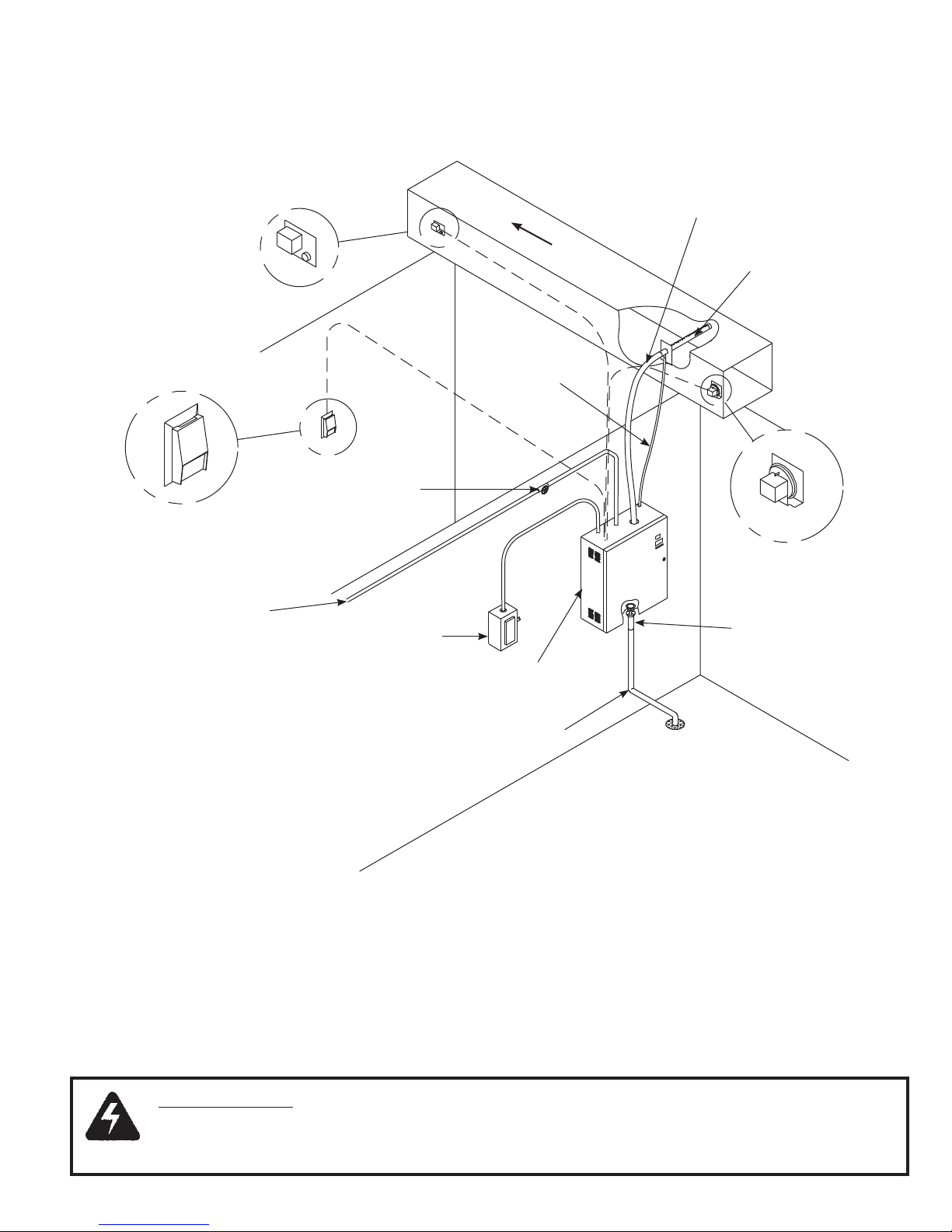
1. The steam distributor pipe must be mounted on a plumb
surface and inclined upward. This is required so the
condensate which forms in the distributor pipe will drain to the
return line and back to the unit, or to a common drain.
2. Insert distributor pipe into duct and secure with four sheet
metal screws (not included).
3. Special distributor pipes are shipped with specific instructions
on how to mount them.
4. If the optional fan distribution unit is to be used, follow the
instructions included with the unit.
CONNECT THE STEAM HOSE
COPPER OR BRASS TUBE IS THE ONLY ACCEPTABLE
SUBSTITUTE FOR CARNES STEAM HOSE OR CONDENSATE
HOSE.
1. The steam hose should be installed so there is a continuous
rise from the humidifier to the distributor pipe. Support the
steam hose at intermediate points to prevent dips, pockets,
sags, or horizontal runs. See Figure I.
2. Any turns should have a minimum radius of 8” to prevent the
hose from kinking. Fasten the steam hose to the distributor
pipe with one of the hose clamps provided.
3. Push the steam hose through the opening on the top of the
humidifier cabinet and slip it over the outlet stub on the top of
the cylinder. Fasten with the hose clamp provided.
4. If long lengths of steam hose or hard tubing are used, the
use of periodic “T’s” to drain condensate should be used.
See Figure D.
CONDENSATE RETURN LINE
1. Fasten the condensate return line to the distributor pipe with
the hose clamp provided.
2. Follow the steam hose to the humidifier cabinet and secure
the return line to the steam hose.
3. Connect the return line to the condensate return inlet with a
hose clamp provided.
4. If it is impossible to maintain a drop to the top of the cabinet,
it is necessary to run the condensate return line directly to the
air gap drain fitting or some other drain.
5. A trap of sufficient size may be necessary to prevent loss of
steam through the return line and reduce the temperature of
condensate water to the common drain. Do not install a trap if
condensate is returned to the top of the cabinet.
STEAM DISPERSION CRITERIA
1. Distributor pipe location must be at a minimum of 6 feet
upstream from any elbows, splits, coils, turning vanes, grilles,
diffusers, etc.
2. If duct temperature is 60°F or less, 10 feet is recommended.
3. Under normal conditions, most absorption distances will be
approximately 4 to 5 feet.
4. If distance recommended is not possible, then a drain pan
may be required.
5. If the air in the duct cannot accommodate the steam output,
the only recourse may be to lower the maximum output of the
unit.
6. If shorter absorption distances are required, 3 feet or less,
multiple distributor pipes could be used. Two pipes split off
one steam hose or two pipes from a dual cylinder unit.
7. If even shorter absorption distances are required, 2 feet
or less, then multi tube short absorption manifolds may be
required.
It is important to keep in mind that there are a lot of variables
involved in proper steam distribution and absorption distances
such as duct length downstream from the dispersion method,
required absorption distance determined by design, capacity of
humidification, velocity of air flow, temperature of air flow, location
of humidifiers, distance between humidifiers to distribution point,
and so on. Proper planning is a prerequisite to good performance.
It is very important that both the steam hose and condensate
return line, whether flexible or hard tubing, be installed so
there are no sags, low points, dips, or horizontal runs. The
steam is at a very low pressure and it cannot overcome any
resistance caused by accumulating water standing in the steam
hose. Accumulation in the condensate return hose will hamper the
flow and may cause water to back up into the duct.
If it is difficult to install the steam hose to prevent sags, it is
recommended that a copper tube be used as a substitute. If a
copper tube is used, a minimum of one inch of insulation must be
applied to prevent excessive condensation (See Figure J). A short
length of steam hose must be used to connect the cylinder in the
humidifier to the copper tube and another short length to connect
the copper tube to the distributor pipe. Size 3/4” copper tube (with
7/8” steam hose) can be used with steam cylinders having output
rates up to 30 pounds per hour. Size 1-1/2” copper tube (with
1-5/8” steam hose) should be used with steam cylinders having
output rates over 30 pounds per hour.
Hose lengths of no longer then 10-20 feet and proper inclines or
routing, as expressed in this manual, will provide the best chance
of having a proper operating humidifier with efficient and effective
steam dispersion.
Figure I Note: Over time and extended
heat, the situations described
in the previous paragraph
can occur. That’s why it is
important to perform monthly
visual inspections to maintain
and correct, improper routing of
steam and condensate lines.
Exaggerated for emphasis.
Figure J
1” Minimum Pipe Insulation
Steam Pipe

10
ELECTRICAL DATA SHEET DEFINITIONS
1. Optional Circuit Breaker designates the quantity and amp
rating of optional factory installed circuit breakers. Circuit
breakers are available in models with an ‘HT
’
prefix. All
models over 48 amps have internal circuit breakers factory
installed.
2. Maximum Lb./Hr. designates maximum capacity of the
humidifier. Units are shipped from the factory preset at the
maximum rate. The output rate may be easily reset after
installation anywhere between 100% and 20% of maximum
capacity.
3. Voltage and Phase designates available phase and nominal
voltages. Single phase units may be operated from two legs
of a three phase supply but the load will be unbalanced.
4. kW is the power rating of the maximum output rate of the
humidifier. If a unit’s max output is adjusted lower, the kW is
reduced proportionally.
5. Line Amp and Disc. Size are amp ratings shown for use in
selecting electrical service requirements.
6. Steam Cylinder shows the quantity and model of steam
generating cylinders mounted inside the humidifier. Each
cylinder requires its own steam distribution pipe, steam hose,
and condensate return line.
7. Cylinder Wire Current is the current a single cylinder wire
should be carrying for a given unit at max output. This does
not include ‘dummy’ electrode wires that never carry any
current, i.e. humidifiers with C65 cylinders and single phase
humidifiers not using AX cylinders.
ELECTRICAL CONNECTIONS
POWER MUST BE OFF BEFORE MAKING ANY ELECTRICAL
CONNECTIONS.
Check unit electrical characteristics on the label on the outside
of the cabinet. The power provided must be the same as what
is described on the label. If it does not, contact your Carnes
Representative. All local and national codes must be followed
when connecting power to the unit.
A fused disconnect or circuit breaker, not provided by Carnes,
MUST be installed per local and national codes. See Table 4 for
recommended circuit ratings. The optional circuit breaker switch
installed in the humidifier is NOT for use as a replacement for
the required external disconnect switch but as a maintenance
convenience.
1. Remove screws securing hinged panel for access to wiring.
See Photos D, E and F for different electrical locations.
2. An opening is provided on the bottom of the electrical
section. Bring electrical power lines through this opening and
connect to electric power terminals.
3. Connect cabinet ground terminals to an independent ground.
DO NOT use the neutral of a four-wire power supply.
4. Replace electrical cover panel. Residential Humidifier
Photo F
Screws
Incoming
Electrical
Photo D
Screws
Incoming
Electrical
HTHH
WARNING: BEFORE MAKING ANY ELECTRICAL
CONNECTIONS SWITCH POWER OFF AT SERVICE
PANEL, FUSED DISCONNECT OR CIRCUIT
BREAKER AND LOCK THE DISCONNECTING
MEANS TO PREVENT POWER FROM BEING
SWITCHED ON ACCIDENTALLY.
(H_AH) (H_DH) (H_GH)
Humidifiers
Photo E
Screws
Incoming
Electrical

11
ELECTRICAL DATA AND UNIT DETAIL SHEET - Table 4
Model
Max
Lb/Hr Voltage Phase kW
Line
Amp
Disc.
Size
Optional
Circuit
Breaker*
Steam
Cylinder
Cyl Wire
Current
HSAH
HTAH
H_AHAU 5 120 1 1.725 14.4 25 1-20 Amp AX220 14.4
H_AHBU 5 208 1 1.725 8.3 15 1-15 Amp AX380 8.3
H_AHDU 5 230 1 1.725 7.5 15 1-20 Amp AX380 7.5
H_AHFU 5 277 1 1.725 6.2 15 1-15 Amp AX380 6.2
H_AHLU 5 380 1 1.725 4.5 15 1-15 Amp AX600 4.5
H_AHQU 5 415 1 1.725 4.2 15 1-15 Amp AX600 4.2
H_AHMU 5 460 1 1.725 3.7 15 1-15 Amp AX700 3.7
H_AHNU 5 575 1 1.725 3.0 15 1-15 Amp AX700 3
H_AHAU 10 120 1 3.45 28.7 45 1-40 Amp AX220 28.7
H_AHBU 10 208 1 3.45 16.6 25 1-25 Amp AX380 16.6
H_AHDU 10 230 1 3.45 15.0 25 1-25 Amp AX380 15
H_AHFU 10 277 1 3.45 12.4 20 1-20 Amp AX380 12.4
H_AHLU 10 380 1 3.45 9.1 15 1-15 Amp AX600 9.1
H_AHQU 10 415 1 3.45 8.3 15 1-15 Amp AX600 8.3
H_AHMU 10 460 1 3.45 7.5 15 1-15 Amp AX700 7.5
H_AHNU 10 575 1 3.45 6.0 15 1-15 Amp AX700 6
HSDH
HTDH
H_DHBU 20 208 1 6.9 33.1 50 1-45 Amp B380 33.1
H_DHDU 20 230 1 6.9 29.9 45 1-40 Amp B380 30
H_DHFU 20 277 1 6.9 24.9 40 1-35 Amp B380 24.9
H_DHLU 20 380 1 6.9 18.1 30 1-30 Amp B600 18.1
H_DHQU 20 415 1 6.9 16.6 25 1-25 Amp B600 16.6
H_DHMU 20 460 1 6.9 15.0 25 1-25 Amp B700 15
H_DHNU 20 575 1 6.9 12.0 20 1-15 Amp B700 12
H_DHCU 20 208 3 6.9 19.1 30 1-25 Amp B500 19.1
H_DHEU 20 230 3 6.9 17.3 30 1-25 Amp B500 17.3
H_DHTU 20 380 3 6.9 10.4 20 1-20 Amp B600 10.4
H_DHWU 20 415 3 6.9 9.6 20 1-20 Amp B600 9.6
H_DHGU 20 460 3 6.9 8.6 15 1-15 Amp B700 8.6
H_DHHU 20 575 3 6.9 6.9 15 1-15 Amp B700 6.9
H_DHCU 30 208 3 10.3 28.7 45 1-40 Amp B500 28.7
H_DHEU 30 230 3 10.3 25.9 40 1-35 Amp B500 25.9
H_DHTU 30 380 3 10.3 15.6 25 1-25 Amp B600 15.6
H_DHWU 30 415 3 10.3 14.4 25 1-25 Amp B600 14.4
H_DHGU 30 460 3 10.3 13.0 20 1-20 Amp B700 13
H_DHHU 30 575 3 10.3 10.4 20 1-15 Amp B700 10.4
HSGH
HTGH
H_GHBU*30 208 1 10.3 49.7*80 2-35 Amp*C62 24.8
H_GHDU 30 230 1 10.3 44.9 70 1-60 Amp C62 22.4
H_GHFU 30 277 1 10.3 37.3 60 1-50 Amp C62 18.6
H_GHLU 30 380 1 10.3 27.2 45 1-40 Amp C62 13.6
H_GHQU 30 415 1 10.3 24.9 40 1-40 Amp C62 12.5
H_GHMU 30 460 1 10.3 22.5 35 1-30 Amp C62 11.3
H_GHNU 30 575 1 10.3 17.9 30 1-25 Amp C62 9.0
H_GHCU 40 208 3 13.8 38.3 60 1-60 Amp C62 19.1
H_GHEU 40 230 3 13.8 34.6 60 1-50 Amp C62 17.2
H_GHTU 40 380 3 13.8 20.9 35 1-35 Amp C65 20.9
H_GHWU 40 415 3 13.8 19.2 30 1-30 Amp C65 19.2
H_GHGU 40 460 3 13.8 17.3 30 1-25 Amp C65 17.3
H_GHHU 40 575 3 13.8 13.8 25 1-20 Amp C65 13.8
* = Circuit Breaker is REQUIRED per NEC 48 amp guideline.

12
ELECTRICAL DATA AND UNIT DETAIL SHEET - Table 4 (continued)
Model
Max
Lb/Hr Voltage Phase kW
Line
Amp
Disc.
Size
Optional
Circuit
Breaker*
Steam
Cylinder
Cyl Wire
Current
HSGH
HTGH
H_GHCU 50 208 3 17.2 47.8 80 2-35 Amp C62 23.9
H_GHEU 50 230 3 17.2 43.2 70 1-60 Amp C62 21.6
H_GHTU 50 380 3 17.2 26.2 40 1-40 Amp C65 26.2
H_GHWU 50 415 3 17.2 24.0 40 1-40 Amp C65 24
H_GHGU 50 460 3 17.2 21.6 35 1-30 Amp C65 21.6
H_GHHU 50 575 3 17.2 17.3 30 1-25 Amp C65 17.3
H_GHCU*60 208 3 20.7 57.4*90 2-40 Amp*C62 28.7
H_GHEU*60 230 3 20.7 51.9*80 2-40 Amp*C62 26
H_GHTU 60 380 3 20.7 31.4 50 1-50 Amp C65 31.4
H_GHWU 60 415 3 20.7 28.8 45 1-45 Amp C65 28.8
H_GHGU 60 460 3 20.7 26.0 40 1-40 Amp C65 26
H_GHHU 60 575 3 20.7 20.8 35 1-30 Amp C65 20.8
H_GHCU*80 208 3 27.5 76.5*125 2-60 Amp*C62 38.2
H_GHEU*80 230 3 27.5 69.2*110 2-50 Amp*C62 34.6
H_GHTU 80 380 3 27.5 41.9 70 1-60 Amp C12 21
H_GHWU 80 415 3 27.5 38.4 60 1-60 Amp C12 19.2
H_GHGU 80 460 3 27.5 34.6 60 1-50 Amp C12 17.3
H_GHHU 80 575 3 27.5 27.7 45 1-40 Amp C12 13.9
H_GHCU*100 208 3 34.4 95.6*150 2-60 Amp*C62 47.8
H_GHEU*100 230 3 34.4 86.4*150 2-60 Amp*C62 43.2
H_GHTU*100 380 3 34.4 52.3*110 2-50 Amp*C12 34.2
H_GHWU 100 415 3 34.4 47.9 80 2-40 Amp C12 24
H_GHGU 100 460 3 34.4 43.3 70 1-60 Amp C12 21.7
H_GHHU 100 575 3 34.4 34.6 60 1-50 Amp C12 17.3
HSHH
HTHH
H_HHCU*125 208 3 43 119.5*200 4-40 Amp*C62 (2) 29.8
H_HHEU*125 230 3 43 108*175 4-40 Amp*C62 (2) 27
H_HHTU*125 380 3 43 65.3*100 2-50 Amp*C12 (2) 16.3
H_HHWU*125 415 3 43 59.8*90 2-45 Amp*C12 (2) 15
H_HHGU*125 460 3 43 54.0*90 2-40 Amp*C12 (2) 13.5
H_HHHU 125 575 3 43 43.2 70 2-30 Amp C12 (2) 10.8
H_HHCU*150 208 3 51.7 143.5*225 4-50 Amp*C62 (2) 35.8
H_HHEU*150 230 3 51.7 129.7*200 4-50 Amp*C62 (2) 32.4
H_HHTU*150 380 3 51.7 78.6*125 2-60 Amp*C12 (2) 19.7
H_HHWU*150 415 3 51.7 71.9*110 2-60 Amp*C12 (2) 18
H_HHGU*150 460 3 51.7 64.8*100 2-50 Amp*C12 (2) 16.2
H_HHHU*150 575 3 51.7 51.9*80 2-35 Amp*C12 (2) 13
H_HHCU*175 208 3 60.3 167.3*300 4-60 Amp*C62 (2) 41.8
H_HHEU*175 230 3 60.3 151.3*250 4-60 Amp*C62 (2) 37.8
H_HHTU*175 380 3 60.3 91.6*150 4-35 Amp*C12 (2) 22.9
H_HHWU*175 415 3 60.3 83.9*150 2-60 Amp*C12 (2) 21
H_HHGU*175 460 3 60.3 75.6*125 2-60 Amp*C12 (2) 18.9
H_HHHU*175 575 3 60.3 60.5*100 2-50 Amp*C12 (2) 15.1
H_HHCU*200 208 3 68.9 191.2*300 4-60 Amp*C62 (2) 47.8
H_HHEU*200 230 3 68.9 172.9*300 4-60 Amp*C62 (2) 43.2
H_HHTU*200 380 3 68.9 104.7*175 4-40 Amp*C12 (2) 26.2
H_HHWU*200 415 3 68.9 95.9*150 4-35 Amp*C12 (2) 23.9
H_HHGU*200 460 3 68.9 86.4*150 2-60 Amp*C12 (2) 21.6
H_HHHU*200 575 3 68.9 69.2*110 2-50 Amp*C12 (2) 17.2
* = Circuit Breaker is REQUIRED per NEC 48 amp guideline.

13
HUMIDIFIER COMPONENT LISTING - Figure K
1. On-Off-Drain Switch
2. Circuit Board
3. Door Interlock Switch
4. Voltage Transformer
5. Current Transformer
6. Distribution Block
7. Ground Lug
8. Contactor
9. High Water Sensor (behind cylinder)
10. Fill Cup
11. Fill Valve (not shown)
12. Steam Hose
13. Electrode Connector
14. LCD - True Touchscreen
15. Circuit Breakers (Option)
16. Cylinder
17. Cylinder Fitting
18. Drain Valve
19. Lock
20. Water Inlet Hose
21. Water Inlet Fitting
22. Fill Valve Inlet Push - On Connector
(not shown)
23. Cooling Fan
1
2
3
4
5
6
7
8
10 12 13 1
14
3
15
16
17
18
19
20
21
23

14
WARNING: BEFORE MAKING ANY ELECTRICAL CONNECTIONS SWITCH POWER OFF AT
SERVICE PANEL, FUSED DISCONNECT OR CIRCUIT BREAKER AND LOCK THE DISCONNECTING
MEANS TO PREVENT POWER FROM BEING SWITCHED ON ACCIDENTALLY.
1. A 7/8” opening is provided on top or bottom of the cabinet. The control wiring should pass through the opening to the
terminal strip.
NOTE: A built-in transformer provides power for the control circuit. No outside power supply is required for the control
circuit.
2. If an air flow switch or high limit humidistat is not used, jumpers must be installed before the humidifier will operate.
Controls should be connected to the terminals on the circuit board as shown in Figure L using #18 AWG wire.
Avoid running control wiring near high voltage wires.
NOTES:
1. Observe proper polarity when using
voltage or current measuring devices.
2. If air flow and high limit switches are
not used, a jumper must be installed.
Supplied By Carnes
Supplied By Others
CONTROL CONNECTIONS - Figure L

15
CONTROLS
CONTROL OPTIONS - Figure M
CONTROL HUMIDISTAT
If an on-off humidistat is used, the humidifier will
generate steam at the max output rate and cycle on or off as
necessary to satisfy the conditioned area requirements. All
humidifiers are preset at the factory for the maximum rating
of the unit. The maximum output may be easily reset to a
lower limit between 20-100% in the settings menu of the
touchscreen.
If Carnes proportional humidistat is used the humidifier will
automatically vary the steam output rate in the range of
20-100% of the humidifier’s maximum output (set by the
user) in response to the 0-10V signal from the humidistat.
However, the output of the humidifier will not drop below
20% of the preset nominal output of the humidifier set at
the factory. Proportional control provides less cycling of the
humidifier.
A wall humidistat or duct mounted humidistat in
the return air may be used. The wall mounted humidistat
is the most common as it allows the setting to be easily
changed to accommodate for changing requirements or to
lower the level of relative humidity in the space to prevent
condensation on windows during extremely cold weather.
In applications where it may be desirable to prevent the
occupants of a space from changing the setting, a duct
mounted humidistat in the return may be used. This is
normally mounted in the equipment room or in the duct
where it is accessible only to maintenance personnel.
AIR FLOW DETECTION
The humidifier control circuit should include some
method to determine air flow. If the steam distributor pipe is
located in a duct where there is no air flow and the control
humidistat is calling for humidity, steam would be
discharged into the duct where it would immediately
condense. Air flow may be detected by several
methods. The humidistat circuit may be interlocked by
using a fan relay if the fan is direct driven. A fan relay is not
recommended if a belt driven fan is used as a broken belt
would stop air flow even though the fan relay was closed.
Among the alternatives is the use of a pressure
differential switch that determines air flow by sensing
a pressure differential caused by air movement in the
duct. A paddle type switch is also available to determine
air flow. The pressure differential switch is normally the
preferred device as it is less susceptible to erratic operation
caused by improper positioning in the duct system. Paddle
switches require careful positioning in the duct to insure
sufficient air flow to activate the switch.
CONTROL HUMIDISTAT AIR FLOW DETECTION CONDENSATION
PROTECTION
WALL HUMIDISTAT
PROPORTIONAL CONTROL
CARNES MODEL HXHCG
OR
WALL HUMIDISTAT
ON-OFF CONTROL
CARNES MODEL HXHAA
OR
DUCT HUMIDISTAT
PROPORTIONAL CONTROL
CARNES MODEL HXHCH
OR
PRESSURE
DIFFERENTIAL
SWITCH
CARNES MODEL HXAAE
OR
DUCT HUMIDISTAT
ON-OFF CONTROL
CARNES MODEL HXHAB
AIR
FLOW
SWITCH
CARNES MODEL HXAAF
OR
DUCT PROPORTIONAL
HIGH LIMIT
HUMIDISTAT
CARNES MODEL HXHCH
DUCT ON-OFF
HIGH LIMIT
HUMIDISTAT
CARNES MODEL HXHAD
OR
OR
DUCT PROPORTIONAL
HIGH LIMIT
HUMIDISTAT
CARNES MODEL HXHAN
WALL HUMIDISTAT
PROPORTIONAL CONTROL
CARNES MODEL HXHAM
OR
OR
DUCT HUMIDISTAT
PROPORTIONAL CONTROL
CARNES MODEL HXHAN
TEMPERATURE COMPENSATED
PROPORTIONAL or
ON-OFF HUMIDISTAT
CARNES MODEL HXHAMT

16
OPTIONAL ACCESSORY CONTROLS
WALL HUMIDISTAT, PROPORTIONAL CONTROL
Unit may be installed on either a flush switch box, a surface switch
box, or directly on a wall.
Mount with Number 6 screws provided for switch box mounting.
Different screws are required for wall mounting (not included).
Mount this humidistat four or five feet above the floor in freely
circulating air for average temperature and humidity to be
controlled for the entire space. Avoid locations near the hot or cold
air ducts and discharge air from the humidifier. Scale range is from
10-90% RH. Differential is 5% non-adjustable.
RED (N. C.)
BROWN (N. O.) (To Terminal 2 or 4)
ORANGE (COMMON)
(To Terminal 2 or 4)
“N.C.” (Red) is switched to
common (Orange) during
RH Rise.
“N.O.” (Brown) is switched
to common (Orange) during
RH Drop.
NOTE: The HXHAA has 6” (152mm) leads and a green
grounding wire for use with non-conducting
conduit.
WALL HUMIDISTAT, ON-OFF CONTROL
Model HXHAM
Model HXHAA
The Model HXHAM is a wall-mounted, microprocessor-controlled
humidistat solution for humidity control. The HXHAM employs
a backlit LCD module, which displays both the ambient
temperature and humidity of the surrounding air. The
embedded software allows user navigation between temperature/
humidity viewing mode, setpoint adjustment mode, and outdoor
temperature/humidity viewing mode.

17
DUCT HUMIDISTAT, ON-OFF CONTROL
This duct mounted humidistat is installed in the return air duct to
sense the humidity level in the area being served. Scale range is
10-60% RH. Differential is 4-6% non-adjustable.
The control should be located in the duct where it will be
affected by normal air flow. The control can be mounted in any
position but should be located on the side of the duct when
possible to make the setpoint adjustment easily accessible.
MOUNTING
HOLES - 2
SETPOINT
ADJUSTMENT
PUSH SCREWDRIVER
IN AND HOLD
PUSH IN
RELEASE - 3
WIRE TO
HUMIDIFIER TERMINAL
2 OR 4
WIRE TO
HUMIDIFIER
TERMINAL 2 OR 4
PUSH IN
TERMINAL - 3
PUSH TO
RELEASE
COM.
DUCT HUMIDISTAT, PROPORTIONAL CONTROL
The Model HXHAN is an intelligent humidistat solution used
exclusively for duct mounted installations. The humidistat
is capable of providing both humidity and temperature
measurements from inside the duct. The microprocessor control
takes the temperature into consideration when calculating the
humidity to provide an extra degree of precision.
Snap-on
plastic
cover
Aluminum housing
DUCT
Allen screws
Use Allen wrench
to unlock cover
Remove any excess insulation from the duct that would prevent
the probe from extending a minimum of 4” (106mm) into the air
stream.
Make a 1-1/2” (38mm) hole in the duct for inserting the probe.
Use a gasket, sealer, or other means to seal the area between the
unit and the duct to ensure proper operation.
WHEN USED TO CONTROL ROOM RELATIVE HUMIDITY WHEN USED AS HIGH LIMIT HUMIDISTAT
Model HXHAB
Model HXHAN

18
AIR FLOW SWITCH, PRESSURE DIFFERENTIAL TYPE
HIGH LIMIT HUMIDISTAT
EXTERNAL DDC CONTROL SIGNALS
The humidifiers can also accept a 0-10 volt DC signal to
modulate the output of the humidifier. Polarity must be
observed. Input impedance is 20K ohms. If a 4-20 mA input
signal is provided to the humidifier a 470 ohm, 1/4 watt resistor
must be installed as shown.
Air flow in the duct may be sensed by using this differential
pressure switch. The differential in pressure between the interi-
or of the duct closes a switch when air is moving. Air pressure
differential as low as .07 w.g. may be sensed with this switch.
Environment:
Ambient Temperature Limits,
Shipping -40 to 140°F (-40 to 60°C).
Operating 35 to 140°F (0 to 60°C).
Humidity, 5 to 95% RH, non-condensing.
Locations, NEMA Type 1 indoor only.
Mounting: In vertical position on any surface free of vibration
Switch to “N.O.” on increase of pressure
(N.C.)
(N.O.) To Terminal 5 or 6
To Terminal 5 or 6 COMMON
•
•
•
When there is an increase of air pressure to above setpoint, the
switch is switched from normally closed (N.C.), common ground
contact to normally open (N.O.) contact. On a decrease of air
pressure to below setpoint, normally closed, common ground
contact of the switch is switched to normally closed contact. Avoid
locations where excessive moisture, corrosive fumes, or vibrations
are present.
Setpoint:
Factory Set, 0.07” (1.8mm) w.g.
Field Adjustable, 0.07 to1” (1.8 to 25.4mm) w.g.
Sensing Element: Neoprene diaphragm.
Adjustment
Note: Units are shipped at minimum setpoint.
To increase setpoint, turn adjustment screw clockwise. Adjustable
0.05 +0.02” to 1.0” (1.25mm +0.5mm to 25mm) w.g. To decrease
setpoint, turn adjustment screw counterclockwise.
The Model HXHAD is available to reduce the potential of
condensation occurring in the supply duct. The control must
be mounted a minimum of 10 feet downstream of the steam
distributor pipe. Setpoint range is 15-95% RH. Differential is 5%
non-adjustable.
The HXHAD may be mounted in any position on the outside
surface of the supply air duct where it is exposed to freely
circulating air (horizontal mounting is preferred).
ORANGE (COMMON)
To Terminal 8 or 10
BROWN (N.O.) To Terminal 8 or 10
RED (N.C.)
Model HXAAE
Model HXHAD
0-10 VDC
PROPORTIONAL SIGNAL
(BY OTHERS)
0-10 VDC
PROPORTIONAL
HIGH LIMIT HUMIDISTAT
(BY OTHERS)
+-+-
4-20ma
PROPORTIONAL
HIGH LIMIT HUMIDISTAT
(BY OTHERS)
470 OHM
RESISTOR
(BY OTHERS)
470 OHM
RESISTOR
(BY OTHERS)
4-20ma
PROPORTIONAL SIGNAL
(BY OTHERS)
+-+-
“N.C.” (Red) is switched to
common (Orange) during
RH Rise.
“N.O.” (Brown) is switched
to common (Orange)
during RH Drop.

19
CONDENSATION PROTECTION
A third device may be desirable to provide condensation
protection in the duct system. A high limit humidistat may be
installed ten feet downstream from the steam distributor pipe. This
humidistat is normally set to 90-95% RH and opens the circuit if
the humidity level in the duct exceeds the setpoint. Use of this
device is recommended particularly when the humidifier is used in
applications where cooling air is being humidified or where a VAV
system may throttle back to a point where air flow is insufficient to
absorb the steam being introduced.
Either an on-off or proportional control high limit humidistat may
be used with Carnes humidifiers. If a proportional humidistat is
used the output of the humidifier will automatically be decreased
to reduce the possibility of condensation. Two proportional
humidistats may be used to control Carnes humidifiers if
desired. One humidistat is in the area to be humidified or
return duct and another humidistat is used as a high limit in
the supply duct. The humidifier will automatically select the
lowest signal to control the humidifier output.
CONTROL HUMIDISTAT / TEMPERATURE COMPENSATED
The HXHAT or HXHAMT can be used if your application has a
requirement for an outdoor temperature compensation feature.
Both controls will provide monitoring of RH percentage and
outdoor temperature, along with automatically adjusting the
RH setpoint as outdoor temperatures change. The HXHAT is
a dry contact on-off humidistat, while the HXHAMT provides a
0-10V signal in either a proportional or on-off configuration.
CONTROL CONNECTIONS
The circuit board can provide either a Carnes legacy 18VDC or an
industry standard 24VAC, as a supply for those humidistats which
require it. The supply for both the control humidistat and high limit
humidistat are output on pin1 of J16 and J17 respectively. 18VDC
is set as the supply default, but the switches on designators SW5
can be flipped to the left to alternatively supply 24VAC as seen in
Photo G for the H690-0107 circuit board (blue). The humidistat and
high limit can be changed independently. The switch labeled Hu is
switched for humidistat voltage output, and the switch labeled HL is
switched for high limit humidistat voltage output. Switch(es) in the
right position will supply 18VDC and switch(es) in the left position
will supply 24VAC.
Connections shown in Figure N are for typical on-off controls.
For Carnes proportional controls see the diagram Figure O. All
controls are shipped with detailed wiring instructions.
EXTERNAL DDC CONTROL SIGNALS
Carnes humidifiers can also accept a 0-10 volt DC signal to
modulate the output of the humidifier. Polarity must be observed.
Input impedance is 20K ohms. If a 4-20 mA input signal is
provided to the humidifier a 470 ohm 1/4 watt resistor must be
installed as shown below (Figure P).
Two cylinder humidifiers may be wired for simultaneous or separate
and independent operation. Controls should be connected to the
terminals on the circuit board as shown below using No. 20 AWG
wire. Attempting to use two wires in a single control connection will
require a No. 22 AWG wire or less. See wiring diagram for parallel
connections. Avoid running control wiring near high voltage primary
wires due to the possibility of interference and signal distortion.
Figure P
0-10 VDC
PROPORTIONAL SIGNAL
(BY OTHERS)
0-10 VDC
PROPORTIONAL
HIGH LIMIT HUMIDISTAT
(BY OTHERS)
+-+-
4-20ma
PROPORTIONAL
HIGH LIMIT HUMIDISTAT
(BY OTHERS)
470 OHM
RESISTOR
(BY OTHERS)
470 OHM
RESISTOR
(BY OTHERS) 4-20ma
PROPORTIONAL SIGNAL
(BY OTHERS)
+-+-
Figure N
ELECTRONIC CONTROL CIRCUIT BOARD
ON/OFF
HUMIDISTAT
AIR FLOW
SWITCH
ON/OFF
HIGH LIMIT
HUMIDISTAT
Figure O
PROPORTIONAL HUMIDISTAT
(BY CARNES)
PROPORTIONAL
HIGH LIMIT HUMIDISTAT
(BY CARNES)
Photo G

20
OPERATION
When the circuit board verifies all four basic controls have
been satisfied (control humidistat, high limit humidistat,
air flow, door interlock), a signal is sent to open a fill
solenoid valve, allowing water to flow across an air gap
into a standpipe. The standpipe provides a column of
water to be fed into the cylinder using gravity. The air gap
prevents the cylinder from pressurizing. See Figure Q.
The steam cylinder normally operates at a pressure of
approximately 1/2 psi.
STEAM
DISTRIBUTOR
PIPE
STEAM
HOSE
FROM POWER
CONTACTOR
CYLINDER
VERTICAL
ELECTRODES
DRAIN
SOLENOID
VALVE
TO DRAIN
STEAM
WATER
AIR GAP
FILL
SOLENOID VALVE
NON CONTACT
HIGH WATER
SENSOR
Figure Q
STAND
PIPE
OVERFLOW
TUBE
CONTROL CONNECTIONS
FOR SAFETY: MAKE SURE TO TURN OFF POWER AT THE
EXTERNAL DISCONNECT BEFORE MAKING ANY INTERNAL
CHANGES TO THE HUMIDIFIER.
1. A 7/8” opening is provided on the top or bottom of the cabinet.
The control wiring should pass through the opening to the
provided connection points at J16, J17, and J18.
2. If an air flow switch or high limit humidistat is not used,
jumpers must be installed before the humidifier will operate.
On J17, jump terminals 2 and 4 together to bypass the high
limit. On J18, jump terminals 1 and 2 together to bypass the
air flow switch.
EXTERNAL MONITORING
Pins 1 and 2 of connector J10, shown in Photo H, are provided for
indicating operation of the humidifier at a remote location. When
the unit is operating, pins 1 and 2 (EXT PWR) are closed. Pins
3 and 4 of connector J10 (EXT SRV) are provided to indicate
the need for service. A “Service Required” warning on the home
screen of the LCD will indicate the type of service that is needed.
Both the EXT PWR and EXT SRV relays have a maximum ratings
of 0.3A at 125VAC or 1A at 24VDC maximum.
CarnesLink is an option to have full external monitoring and
control of your Carnes humidifier(s) by allowing the humidifier(s)
to link to a Building Management System (BMS) using one of the
following protocols: BACnet®(MS/TP), Modbus®(RTU),
Metasys®(N2) and Siemens®(FLN).The user friendly interface
on the True Touchscreen makes setting up CarnesLink easy
and convenient. (See the CarnesLink Communication Protocol
Installaion, Operation, and Maintenance Manual for further info.)
NETWORKING
If multiple units are required due to high capacity demand
(over 200 lb. per hour, single unit), networking can be done.
Units can be interconnected with parallel signal wiring. This setup
is usually done to facilitate running multiple units from a single
signal control (Humidistat, BMS System, etc.). For other
networking requirements, please contact factory.
As mineral deposits build up within the cylinder the water
level will slowly rise to uncovered electrode surfaces to
maintain the desired steam output rate. When mineral
deposits have covered all available electrode surfaces,
current flow will be reduced to a level where the desired
steam output cannot be reached and the service light will
signal the need for maintenance. When the cylinder is filled
with minerals it is easily changed in less than five minutes
(not including cool down time).
Important Note: Due to the many variables effecting the
operation of humidifiers (water condition, conductivity,
hardness, etc.) it could take up to 24 hours of operation
before a humidifier is truly operating normally and the water
is completely conditioned. Conditioned water is a state
where the amount of minerals dissolved within the water
is at a steady state. Conditioned water is more conductive
than new water from the fill valve.
The circuit board also closes a power contactor allowing
current to flow to vertical electrodes sealed inside the
cylinder. Current flows between the electrodes using
minerals in the water as a conductor. The water is heated
to boiling and converted to steam which leaves the cylinder
through the flexible steam hose which is connected to the
steam distributor pipe.
The circuit board reacts to current flow between the
electrodes and automatically opens the fill solenoid valve
when more water is required to maintain the desired
output rate and closes when the desired rate is reached.
The operation of the drain solenoid valve is automatically
controlled by the circuit board which responds to any
changes in water conditions and drains the required
quantity of water to provide stable operation and long
cylinder life.
Photo H
Table of contents
Popular Humidifier manuals by other brands

Vicks
Vicks EasyCare+ Top Fill use and care manual

White Rodgers
White Rodgers HFT2700 owner's manual

HygroMatik
HygroMatik MiniSteam instruction manual

Bionaire
Bionaire BCM1745 Instruction leaflet

Neptronic
Neptronic SKE SERIES Installation instructions & user manual

Canary Products
Canary Products O Breeze FM102BL instruction manual