Intersurgical PMH7000 User manual

Instruction For Use PMH7000 Version 2
Revision 03 23 July 2019 Page 1 of 20
Intersurgical
Humidifier Heater Base PMH7000
Instructions for Use
Distributed by:
Intersurgical Ltd, Crane House, Molly Millars Lane, Wokingham,
Berkshire, RG41 2RZ, UNITED KINGDOM
T: +44 (0) 118 9656 300
www.intersurgical.com

Instruction For Use PMH7000 Version 2
Revision 03 23 July 2019 Page 2 of 20
Table of Contents
1. INTRODUCTION----------------------------------------------------------------------------4
1.1Intended Use -------------------------------------------------------------------------------------------------------------4
1.2 Features of the device-------------------------------------------------------------------------------------------------4
2. SAFETY PRECAUTIONS ----------------------------------------------------------------4
2.1 Warnings, Cautions and Notes-------------------------------------------------------------------------------------4
2.2 Symbols--------------------------------------------------------------------------------------------------------------------6
3. SPECIFICATIONS--------------------------------------------------------------------------6
3.1 Power Requirements --------------------------------------------------------------------------------------------------6
3.1.1 Operating Voltage -------------------------------------------------------------------------------------------------6
3.1.2 Line Frequency-----------------------------------------------------------------------------------------------------6
3.1.3 Power Consumption-----------------------------------------------------------------------------------------------6
3.1.4 Current Rating------------------------------------------------------------------------------------------------------6
3.1.5 Heater Plate Power------------------------------------------------------------------------------------------------6
3.1.6 Heater Wire Power ------------------------------------------------------------------------------------------------7
3.1.7 Heater Plate Temperature---------------------------------------------------------------------------------------7
3.1.8 Heater Wire Resistance------------------------------------------------------------------------------------------7
3.2 Physical Dimensions --------------------------------------------------------------------------------------------------7
3.2.1 Size (Without Humidification Chamber Installed)----------------------------------------------------------7
3.2.2 Weight ----------------------------------------------------------------------------------------------------------------7
3.3 Environmental -----------------------------------------------------------------------------------------------------------7
3.3.1 Operating Temperature ------------------------------------------------------------------------------------------7
3.3.2 Storage Temperature---------------------------------------------------------------------------------------------7
3.3.3 Operating Relative Humidity ------------------------------------------------------------------------------------7
3.3.4 Storage Relative Humidity---------------------------------------------------------------------------------------7
3.3.5 Atmospheric Pressure--------------------------------------------------------------------------------------------7
3.4 Electromagnetic Interference---------------------------------------------------------------------------------------7
3.5 Compliant Accessories--------------------------------------------------------------------------------------------- 10
3.6Settings for Ventilated Patients---------------------------------------------------------------------------------- 10
3.7 Capacity of Humidifying Chamber------------------------------------------------------------------------------ 10
4. TEMPERATURE --------------------------------------------------------------------------10
4.1 Set Temperature Range--------------------------------------------------------------------------------------------- 10
4.2 Temperature Display------------------------------------------------------------------------------------------------- 10
5. FRONT PANEL----------------------------------------------------------------------------11
5.1 Front Panel View------------------------------------------------------------------------------------------------------ 11
5.2 Front Panel-------------------------------------------------------------------------------------------------------------- 11
5.3 Front Panel Functional Description ---------------------------------------------------------------------------- 11

Instruction For Use PMH7000 Version 2
Revision 03 23 July 2019 Page 3 of 20
5.4 Other Functions------------------------------------------------------------------------------------------------------- 13
6. SIDE PANEL -------------------------------------------------------------------------------14
6.1 Left Side View---------------------------------------------------------------------------------------------------------- 14
6.2 Left Side Panel Description --------------------------------------------------------------------------------------- 14
7. ASSEMBLY WITH BREATHING CIRCUIT----------------------------------------15
8. SET UP AND OPERATION OF THE HUMIDIFIER BASE--------------------16
9. MAINTENANCE & REPAIR------------------------------------------------------------17
9.1 Basic Checks----------------------------------------------------------------------------------------------------------- 17
9.2 Dual Temperature Probe Check---------------------------------------------------------------------------------- 17
10. REPROCESSING-------------------------------------------------------------------------18
11. REPAIR--------------------------------------------------------------------------------------18
12. DISPOSAL----------------------------------------------------------------------------------18
13. TROUBLE SHOOTING------------------------------------------------------------------18
14. COMPLIANT ACCESSORIES --------------------------------------------------------20

Instruction For Use PMH7000 Version 2
Revision 03 23 July 2019 Page 4 of 20
1. Introduction
1.1 Intended Use
The Humidifier Heater Base PMH7000 is intended to add moisture and to warm the breathing gasses through ET tubes,
Tracheostomy tubes or any NIV interface for any patient adult, paediatric or neonate who needs mechanical or positive
pressure ventilation.
1.2Features of the device
PMH7000 Humidifier base features a dual temperature servo control system, which regulates the temperature of the gas
delivered to the patient and the gas at the outlet of the humidifying chamber. It continuously monitors temperatures using a
platinum dual temperature probe. The Humidifier base warms and humidifies the gas through the humidifier chamber and
in addition a heated wire in the patient breathing circuit further controls and keeps the same gas warm. The operator is
allowed to set the temperature of the chamber outlet gas, which controls the gas humidity just before it is delivered to the
patient. Temperature is displayed on the front panel.
A dual heated wire adaptor lead (REF 5601000) is separately available for the PMH7000 Humidifier base, for use with a
dual heated wire system, a single adaptor lead (REF 5600000) is available when using a single heated wire system.
PMH7000 Humidifier base is equipped with alarms, which activate audible and visual indicators to alert the operator of
adverse conditions. Alarms are provided for high and low airway temperature, high and low chamber outlet temperature,
dual temperature probe disconnect or fault condition, heated wire fault connection, a light on the front panel identifies the
area of alarm.
Various safety monitoring functions are incorporated to detect and prevent the over-heated conditions which may affect the
patient conditions or damage the unit itself. For patient safety, alarm conditions continue for 10 minutes and the Humidifier
base turns off unless set levels are achieved or adjusted by the operator.
2. Safety Precautions
The information provided in this manual should be read and fully understood before using the PMH7000 Humidifier base.
The information applies to the Humidifier base as well as any optional equipment and accessories used with the device.
2.1Warnings, Cautions and Notes
In this manual, a WARNING describes the actions necessary to prevent injury or loss of life. A CAUTION describes the
actions to be taken to protect the equipment from being damaged. A NOTE contains precautions, procedures and actions.
The principal WARNING and CAUTION notices to be observed during use of the PMH7000 are included in this
section for emphasis.
WARNING ! FOR USE BY TRAINED PERSONNEL ONLY: The PMH7000 Humidifier base and accessories are
designed for use by trained medical personnel acting under physician’s orders. It is prohibited that anyone other than
qualified medical personnel use these Humidifier bases.
WARNING ! OBSERVE BEST PRACTICE: The instructions in this manual do not supersede established medical
procedures or staff preferences concerning patient care. “Best Practice” as determined by the medical community and/or
individual institutions is always to be observed.
WARNING ! SETTING-UP: Do not place the Humidifier base and the humidifying chamber higher than patient,
otherwise, condensed water droplets may enter the patient airway.
WARNING ! SETTING-UP: Do not fill the humidifying chamber above the maximum fill level. Droplets of water may
enter into the patient breathing system if the chamber is overfilled.
WARNING ! SETTING-UP: Do not fill the chamber with distilled water in excess of 30C.
WARNING ! SETTING-UP: Ensure that the water level in the chamber is correct before use. Failure to ensure correct
water level in the chamber at start-up could result in the under humidification of the patient (see chamber IFU for details).
WARNING ! SETTING-UP: Ensure that the dual temperature probes are inserted correctly into the breathing system
ports as shown in diagrams on pages 17. Failure to do so may result in gas delivery to the patient above 43C. Before
connecting to the patient, ensure the ventilator or gas delivery device is operating properly and check the flow rate and
pressure levels are functioning correctly.
WARNING ! OPERATION: Prior to the use of this Humidifier base, the user must be totally familiar with the use,
application and safety procedures associated with this device.
WARNING ! OPERATION: Periodic checks of the temperature must be made to ensure that the temperature of the gas
delivered to the patient is as set by trained medical personnel. Excessive heat delivered to the patient may cause harm to
the airways and/or other hazards to the patient.

Instruction For Use PMH7000 Version 2
Revision 03 23 July 2019 Page 5 of 20
WARNING ! OPERATION: Before connecting the breathing system to the patient, ensure the ventilator or gas delivery
device is operating properly and check the flow rate and pressure levels are functioning correctly.
WARNING ! OPERATION: If the room temperature is lower than the Humidifier base patient set temperature, there may
be an increase in condensation in the patient breathing system. A build up of excess fluid in the system should be
monitoring carefully at all times.
WARNING ! OPERATION: Please keep watching and checking the water level in the humidification chamber.
WARNING ! OPERATION: Do not use Humidifier base without gas flow. If gas flow is interrupted or significantly
decreased, turn off the Humidifier base until the gas flow has resumed and stabilised.
WARNING ! EXPLOSIVE HAZARD: Do not use this equipment in the presence of flammable gases or anaesthetic
gases.
WARNING ! EXPLOSIVE HAZARD: Do not use this equipment in an OXYGEN RICH ENVIRONMENT; for example
during hyperbaric oxygen therapy. It could lead to an explosion.
WARNING ! BURN HAZARD: Do not touch the heater plate of the humidifier base and metal edge of the chamber until
it has been given sufficient time to cool. The heater plate and metal edge of the chamber can achieve temperatures
above 85C immediately after use.
WARNING ! BURN HAZARD: Do not cover patient circuit with insulated materials, such as sheets, towels or blankets,
as it may cause the circuit to be overheated. Patient or operator contact with the circuit may result in burns. To protect the
patient from burns, the patient circuit should not be in contact with the patient’s skin. Also, a distorted circuit could cause
flow disruption.
WARNING ! ALARMS: If an alarm condition cannot be identified the humidifier base should be turned off immediately
and the humidifying chamber should be removed from the patient system. Some alarm conditions can cause patient
injury if not acted upon.
WARNING ! ALARMS: No alarms sound or alarm location lights on the front panel can be activated while the system is
shut down or while the protective thermostat is activated.
WARNING ! RECOMMENDED ACCESSORIES: Use accessories (humidifying chambers, patient systems, heater wire
and other accessories) recommended by the manufacturer. Patient systems, chambers and adaptor leads commercially
available from other manufacturers have not been fully validated.
WARNING ! SHOCK HAZARD: A shock hazard may exist if this system is not properly grounded. The system is
designed to operate with a 3-wire AC power source containing a separate ground wire. The grounding wire must not be
removed or cut off. Grounding reliability can be assured only if connected correctly to the receptacle [hospital
specification] with proper grounding.
WARNING ! CLEANING AND CARE: As a general safety precaution, the unit must turn off and AC power must
disconnect before performing any cleaning or maintenance procedures.
WARNING! SERVICE AND/OR MAINTENANCE: Service and/or maintenance should be performed by an authorized
and fully trained technician familiar with the device, please contact your sales provider
WARNING ! Never use this device with an HME (Heat and Moisture Exchanger) or HMEF (Heat and Moisture Filter).
WARNING ! Humidifier bases and dual temperature probes must be cleaned before use in line with this manual’s
section 10. Reprocessing. Dual temperature probes are not clinically clean when shipped.
WARNING ! DO NOT IMMERSE, STERILIZE or AUTOCLAVE the humidifier base.
WARNING ! Refer to the specifications of humidifying chamber and patient breathing circuits concerning the maximum
operating pressure.
WARNING ! If this Humidifier base is used outside the specified operating temperature, it may lead to an inadequate
warming/humidifying capability. Contact your sales provider for advice.
WARNING ! The operator, should not touch the temperature probe connector and the patient simultaneously.
WARNING ! No modification of this equipment is allowed.
CAUTION ! U.S. Federal Law restricts the sale of this device to or on the order of a licensed physician.
Instruction For Use PMH7000 Version 2
Revision 03 23 July 2019 Page 6 of 20
CAUTION ! Contact your sales provider for all technical support and services.
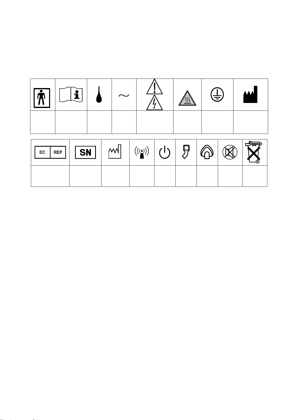
2.2Symbols
The labels or labelling for this product have the following symbols. Please read description below
Symbols:
Type BF
Applied
Part
Consult
instruction for
use
IPX1
Drip Proof
Alternating
Current
CAUTION
Electrical Shock
Hazard
Refer to qualified
service personnel
WARNING
Hot surfaces
may exceed
85°C
Protective
Earth
(Ground)
Manufacturer
Authorized
Representative In
The European
Community
Serial Number
Date of
manufacture
Non-
ionizing
Radiation
Power
On/Off
IPPV
Mode
NPPV
Mode
Alarm
Silencer
Button
Do not
discard
3. Specifications
WARNING! EXPLOSIVE HAZARD: Do not use this equipment in the presence of flammable gases or anaesthetic gases.
Electric Shock Classification: Class I, type BF Applied Part
Protection against Water Classification: IPX1
Mode of Operation Classification: Continuous Operation
3.1Power Requirements
The Humidifier base is set for the correct voltage at the factory prior to shipment, but before connecting to AC power,
ensure that the voltage label shows the correct setting.
3.1.1Operating Voltage
230V
3.1.2Line Frequency
230V - 50Hz
3.1.3Power Consumption
250 VA Maximum
3.1.4Current Rating
230V - 1.1A
3.1.5Heater Plate Power
150 Watts
3.1.6Heater Wire Power
Inspiratory 44 Watts (Max. DC24V, 1.8A), regulated

Instruction For Use PMH7000 Version 2
Revision 03 23 July 2019 Page 7 of 20
Expiratory 44 Watts (Max. DC24V, 1.8A), regulated
3.1.7Heater Plate Temperature
115CThermostat regulated (normal operation)
130C Thermostat limited (AC power disabled)
3.1.8Heater Wire Resistance
11 to 50 Ω (ohms)
3.2Physical Dimensions
3.2.1Size (Without Humidification Chamber Installed)
Height - 145mm / Width - 140mm / Depth - 180mm
3.2.2Weight
1.7 kg. (approx.)
3.3Environmental
For stand and pole use, the PMH 7000 is designed to be fixed with a bracket, and should be used in the upright position.
Do not use the complete system in a location with high temperature or high humidity. If the Humidifier base is reclined
more than the tolerance of 20 degree in any direction, the Humidifier base must not be used. Do not close or obstruct any
of the air venting on the base unit as this may cause overheating. It is recommended to keep the gas inlet temperature in a
range of ± 1C of the room temperature.
3.3.1Operating Temperature
20C to 26C
(68F to 79F)
3.3.2Storage Temperature
-20C to 60C
(-4F to 140F)
3.3.3Operating Relative Humidity
30 to 75%
Non-condensing
3.3.4Storage Relative Humidity
10 to 95%
Non-condensing. That includes the transportation time.
3.3.5Atmospheric Pressure
700 to 1060 hPa
3.4Electromagnetic Interference
PMH7000 complies with limitations as specified in IEC 60601-1-2 for Medical Products.
The function of this machine may be adversely affected by the operation of other equipment, such as high frequency
surgical diathermy equipment, short wave therapy equipment, defibrillators or MRI equipment, if located nearby. Place the
Humidifier base away from the above devices which may give adverse affect to the function of the Humidifier base.
■About EMC (Electromagnetic Compatibility)
EMC means that the subjective devices shall comply with the following Requirements.
・There should be no noise disturbances over the tolerance emitted from the device, which affect the function of
neighbouring equipment. (Emission)
・The device shall be made durable with the electromagnetic environment such as against the noise emitted from
neighbouring equipment and shall be operated in normal function. (Immunity)
EMC standards representing IEC 60601-1-2 specifies the following.
1) To keep the level of affection under the tolerated level to other equipments by the noise emitted from the device
itself.
2) To keep the level of affection to the device itself by electromagnetic frequency of other equipments (like mobile
phone) under tolerated level.

Instruction For Use PMH7000 Version 2
Revision 03 23 July 2019 Page 8 of 20
As there is requirement under IEC 60601-1-2: 2007 that the detailed information on EMC environmental conditions shall
be provided to the user so as to make the device being operated safely, the technical explanation relating EMC
standards are described below. (For further details, please refer to IEC 60601-1-2: 2007).
■ Technical Information on EMC (Electromagnetic Compatibility)
Electro-medical equipment requires an adequate attention to EMC standard and specifications, and shall be used under
the following instructions.
NOTE:
・The device requires an adequate attention to EMC standards and specifications, and shall be used under the EMC
information described in this section.
・The device may be affected by other portable and mobile RF communication equipments.
Guidance and manufacturer’s declaration –electromagnetic emissions
The PMH7000 is intended for use in the electromagnetic environment specified below. The customer or the user of the
PMH7000 should assure that it is used in such an environment.
Emission test
Compliance
Electromagnetic environment - guidance
RF emissions
CISPR 11
Group 1
The PMH7000 uses RF energy only for its internal function.
Therefore, its RF emission are very low and are not likely to cause
any interference in nearby electronic equipment.
RF emissions
CISPR 11
Class B
The PMH7000 is suitable for use in all establishments, including
domestic establishments and those directly connected to the public
low-voltage power supply network that supplies buildings used for
domestic purposes.
Harmonic emissions
IEC 61000-3-2
Class A
Voltage fluctuations/
flicker emissions
IEC 61000-3-3
Complies
Guidance and manufacturer’s declaration –electromagnetic immunity
The PMH7000 is intended for use in the electromagnetic environment specified below. The customer or the user of the
PMH7000 should assure that it is used in such an environment.
Immunity test
IEC 60601-1 test
level
Compliance
level
Electromagnetic environment - guidance
Electrostatic
discharge(ESD)
IEC 61000-4-2
±6kV contact
±8kV air
±6kV contact
±8kV air
Floor should be wood, concrete or ceramic tile.
If floors are covered with synthetic material,
the relative humidity should be at least 30%.
Electrical fast transient /
burst
IEC 61000-4-4
±2kV for power
supply lines
±1kV for
input/output lines
±2kV for power
supply lines
N/A*
Mains power quality should be that of a typical
commercial or hospital environment.
Surge
IEC 61000-4-5
±1kV line(s) to
line(s)
±2kV line(s) to
earth
±1kV line(s) to
line(s)
±2kV line(s) to
earth
Mains power quality should be that of a typical
commercial or hospital environment.
Voltage dips, short
interruptions and voltage
variations on power supply
input lines
IEC 61000-4-11
<5% UT
(>95 % dip in UT)
for 0.5 cycle
40% UT
(60 % dip in UT)
for 5 cycle
70% UT
(30 % dip in UT)
for 25 cycle
<5% UT
(>95 % dip in UT)
for 5s
<5% UT
(>95 % dip in UT)
for 0.5 cycle
40% UT
(60 % dip in UT)
for 5 cycle
70% UT
(30 % dip in UT)
for 25 cycle
<5% UT
(>95 % dip in UT)
for 5s
Mains power quality should be that of a typical
commercial or hospital environment. If the user
of the PMH7000 requires continued operation
during power mains interruptions, it is
recommended that the PMH7000 be powered
from an uninterruptible power supply or
battery.

Instruction For Use PMH7000 Version 2
Revision 03 23 July 2019 Page 9 of 20
Power frequency
(50/60Hz) magnetic field
IEC 61000-4-8
3A/m
3A/m
Power frequency magnetic fields should be at
levels characteristic of a typical location in a
typical commercial or hospital environment.
Portable and mobile RF communications
equipment should be used no closer to any
part of the PMH7000 including cables, than the
recommended separation distance calculated
from the question applicable to the frequency
of the transmitter.
Recommended separation distance
Conducted RF
IEC 61000-4-6
3Vrms
150kHz to 80 MHz
3V
d =1.2√P
Radiated RF
IEC 61000-4-3
3V/m
80MHz to 2.5GHz
3V/m
d =1.2√P80MHz to 800MHz
d =2.3√P800MHz to 2.5GHz
where Pis the maximum output power rating
of the transmitter in watts (W) according to the
transmitter manufacturer and dis the
recommended separation distance in
meters(m).
Field strengths from fixed RF transmitters, as
determined by an electromagnetic site surveya
should be less than the compliance level in
each frequency range b
Interference may occur in the vicinity of
equipment marked with the following symbol:
NOTE 1 At 80MHz and 800MHz, the higher frequency range applies.
NOTE 2 These guidelines may not apply in all situations. Electromagnetic propagation is affected by absorption and
reflection from structures, objects and people.
a Field strengths from fixed transmitters, such as base stations for radio (cellular / cordless) telephones and land mobile
radios, amateur radio, AM and FM radio broadcast and TV broadcast cannot be predicted theoretically with
accuracy. To assess electromagnetic environment due to fixed RF transmitters, an electromagnetic sites survey
should be considered. If the measured field strength in the location in which the PMH7000 is used exceeds the
applicable RF compliance level above, the PMH7000 should be observed to verify normal operation. If abnormal
performance is observed, additional measures may be necessary, such as reorienting or relocating the PMH7000.
b Over the frequency range 150kHz to 80MHz, field strengths should be less than 3V/m.
N/A: not applicable, this test item does not have to be performed.
*The test on signal ports is not applicable since the signal cables are not longer than 3m according to the manufacturer’s
specification.
Recommended separation distances between
portable and mobile RF communications equipment and the PMH7000
The PMH7000 is intended for use in an electromagnetic environment in which radiated RF disturbances are controlled.
The customer or the user of the PMH7000 can help prevent electromagnetic interference by maintaining a minimum
distance between portable and mobile RF communications equipment (transmitters) and the PMH7000 as
recommended below, according to the maximum output power of the communications equipment.
Rated maximum output
power of transmitter
W
Separation distance according to frequency of transmitter
m
150kHz to 80MHz
d = 1.2√P
80MHz to 800MHz
d = 1.2√P
800MHz to 2.5GHz
d = 2.3√P
0.01
0.12
0.12
0.23
0.1
0.38
0.38
0.73
1
1.2
1.2
2.3
10
3.8
3.8
7.3
100
12
12
23

Instruction For Use PMH7000 Version 2
Revision 03 23 July 2019 Page 10 of 20
For transmitters rated at a maximum output power not listed above, the recommended separation distance din meters
(m) can be estimated using the equation applicable to the frequency transmitter, where P is the maximum output
power rating of the transmitter in watts (W) according to the transmitter manufacturer.
NOTE 1 At 80MHz and 800MHz, the separation distance for the higher frequency range applies.
NOTE 2 These guidelines may not apply in all situations. Electromagnetic propagation is affected by absorption and
reflection from structures, objects and people.
3.5Compliant Accessories
Dual temperature probe (REF 7700000) and single heated wire adaptor lead (REF 5600000) or dual heated wire adaptor
lead (5601000).
Patient systems, chambers, adaptor leads and dual temperature codes commercially available from other manufacturers
have not been fully validated. As the PMH7000 Humidifier base incorporates a shunt fuse, the PMH7000 is not compatible
for use with electrical adaptors containing a shunt fuse.
3.6Settings for Ventilated Patients
IPPV mode:
When the gas flow is in the range of 10L/min to 60L/min, an absolute humidity of at least 33mg/L is delivered.
NPPV mode:
When the gas flow is in the range of 10L/min to 60L/min, an absolute humidity of at least 10mg/L is delivered.
3.7Capacity of Humidifying Chamber
Effective capacity of humidifying chamber is less than 500mL.
4. Temperature
The airway temperature and chamber temperature are servo controlled by the Humidifier base.
4.1Set Temperature Range
Patient Side
30°C to 40°C
(increments 1°C)
Chamber Side
26°C to 43°C
(increments 1°C)
Temperature setting of patient side vs. chamber side temperature is
in relationship within the range of -4°C to +3°C.
4.2Temperature Display
Patient side temperature or chamber side temperature is displayed by switching using , which is
displayed in Chapter 5.1 while operated in manual mode.
Patient Side Temperature Display Range
10°C to 47°C increments 0.1°C
Chamber Side Temperature Display Range
10°C to 45°C increments 0.1°C

Instruction For Use PMH7000 Version 2
Revision 03 23 July 2019 Page 11 of 20
5. Front Panel
5.1 Front Panel View
5.2 Front Panel
5.3Front Panel Functional Description
1
Power Button
2
Temperature Display
3
Mode Change
4
Mode Display LED
5
Scroll Button
6
Set (temperature in manual mode) Button
7
“°C” Display
8
Status Indication LED
ⓐPatient Side LED
ⓑChamber Outlet Side LED
ⓒHeater Wire LED
ⓓTemp. Probe
ⓔ(Unit Fault ) LED
9
Alarm Silencer Button
1
Power Button:
Power can be turned on/off by pressing this button for more than 1 second.
While it is turned on, it activates all the initial check-up which include CPU and temperature displays, all the
LED test, and alarm sound test as well. When it is turned off, alarm sound verification will be activated only
once in short time.
Note: In order to verify the functionality of the alarm system, during the power on self-test, the operator
should check that all LED lights, and that the buzzer sounds.
2
2-1
Temperature Display:
The display normally shows either chamber outlet temperature or patient temperature whichever is
selected. Opposite selection can be made by holding ▲ (Up) button when turning ON the device.
LED ⓐlights in green: indicating patient side temperature.
LED ⓑlights in green: indicating chamber side temperature.
To briefly display the opposite temperature, hold button ⑨(ALM) for 2 seconds, the display indicates the
opposite side temperature and then the display returns to the original display conditions automatically after
10 seconds.
a
b
c
e
d

Instruction For Use PMH7000 Version 2
Revision 03 23 July 2019 Page 12 of 20
3
Mode Change:
“IPPV” mode is set as a default when the unit is delivered out from factory. Keep pressing the “MODE”
button for 2 seconds, it changes with following order: IPPV→NPPV→MANUAL, so select necessary mode.
4
Mode Display LED: IPPV→NPPV→MANUAL
IPPV Mode: This mode is for patients with a tracheal tube. The preset for the patient side is 40C and
chamber side is 37C automatically.
NPPV Mode: This mode is for patients with NIV (Non Invasive Ventilation) masks. The preset for the patient
side is 34C and chamber side is 31C automatically.
MANUAL mode: This mode allows the selection of optional temperature of both patient side and chamber
side. (Refer to 5 for the details.)
On selecting MANUAL mode, a sound confirmation will be activated and the display will show the set
patient temperature and then the currently set chamber side temperature for approximately 2 seconds each
as confirmation of the initial setting. After 2 seconds, LEDⓐ, ⑧status indication, blinks in green, and the
patient side temperature can be set. Temperature setting can be changed by ⑤scroll button. While
pressing ⑥“Set” button, operate ⑤scroll button to set the chamber side temperature.
If you do not make changes for 10 seconds, the unit will return to the normal state, and display will be as
selected.
*Patient side: 30°C to 40°C (increments 1°C)
*Chamber side: 26°C to 43°C (increments 1°C)
*Temperature setting of patient side vs. chamber side temperature is in relationship within the range of -
4°C to +3°C.
*The pre-set temperatures are 37C at chamber side and 37°C at patient side when the unit is shipped
out from the factory. Refer to ⑤section for how to change pre-set value.
5
Scroll Button: ▲up ▼down
In “MANUAL”mode, these buttons allow the user to change the temperature setting of both patient side and
chamber side.
Press either ▲up or ▼down button for more than 2 seconds, patient icon will blink quickly in green and
display patient temperature setting. At this time, temperature setting changes can be made by pressing
▲up and ▼down button. Press the button once, and the temperature value changes 1°C. Holding the
button will not change the temperature value continuously.
Warning !
Rain out in the patient circuit will increase when room temperature is lower than patient side set
temperature.
6
Status Indication LED:
There are 5 LED indicators showing position around the heater base and breathing system on a diagram on
the front panel.
1. In normal operation the temperature shown in main display (2) is measured from the point indicated by
LED ⓐ(patient temperature) or LED ⓑ(chamber temperature) whichever is illuminated in green.
2. On entering manual mode the temperature shown in display (2) will be the patient temperature when
LED ⓐis blinking green and chamber temperature when LED ⓑis blinking. To change temp see section
5
3. Illuminated LED shows location of the fault, as detailed below.
LED ⓐPatient Temperature
Flashes red - the measured temperature has exceeded the set temperature by 2C, or exceeded a
maximum temperature of 43C (in this case there is a high priority audible alarm and the heated wire is
turned off).
Flashes red - Patient Probe temperature has not increased by >2C in 2 minutes after Power-on
(in this case there is a high priority audible alarm).
Flashes yellow –the measured temperature is 4C below the set temperature (in this case a medium
priority audible alarm sounds intermittently).
Note: this alarm is disabled while the Humidifier base warms up
LED ⓑChamber temperature
Flashes red - The measured temperature exceeds the set temperature by 4C for more than 20 minutes,
or the measured temperature exceeds the set level by 10C (in this case there is a high priority audible
alarm and the heated wire is turned off).
Flashes yellow –the measured temperature is 4C below the set temperature for more than 20 minutes, or
the measured temperature is below the set temperature by 10C (in this case a medium priority audible
alarm sounds intermittently).
Note: this alarm is disabled while the Humidifier base warms up.

Instruction For Use PMH7000 Version 2
Revision 03 23 July 2019 Page 13 of 20
5.4Other Functions
Prevention of abnormal temperature rise.
To prevent abnormal temperature rise, a thermal fuse is used for the safety of the power circuit. Should there be a short-
circuit due to some damage, the power will cease automatically.
When the patient side temperature exceeds +43C, the patient icon LED (A) lights up in red and the alarm sounds
intermittently. Then, a solid state relay (ssr) is activated and stops the temperature rise.
If the heater plate temperature exceeds +130C, a thermostat will cease the power supply to the circuit, and stop operation.
At that time, all displays are cleared, and the unit is not active.
Warning !
Under such condition, stop using the PMH7000 Humidifier base and contact your sales
provider immediately for assistance.
LED ⓒHeated wire
Flashes red –The heated wire is disconnected or faulty (in this case a high priority audible alarm sounds
intermittently).
LED ⓓDual temperature probe
Flashes red - The dual temperature probe (7700000) is disconnected or faulty (in this case a high priority
audible alarm sounds intermittently).
LED ⓔHeater plate
Flashes red - The measured chamber temperature does not rise more than 2C in 20 minutes from start
up (in this case a high priority audible alarm sounds intermittently).
Note: If an alarm state is left unresolved for 10 minutes, then the device displays “000”, and stops
operating. The Humidifier base requires turning off and on again to resume operation.
Note: To check the alarm status, operator should be located in the same room with the patient.
Alarm Silence Button “ALM”:
It mutes all audible alarms for 2 minutes.
Mute will end after 2 minutes. If the alarm situation continues, the alarm will again sound intermittently after
2 minutes.
If any new alarm condition occurs under the mute mode other than original alarm condition, the original
mute mode will be invalid and the alarm will activate against the new alarm condition.
Note: Pressing the “ALM”button for more than 2 seconds will switch the display After 10 seconds it will
revert back and display airway temperature.
Instruction For Use PMH7000 Version 2
Revision 03 23 July 2019 Page 14 of 20
6. Side Panel
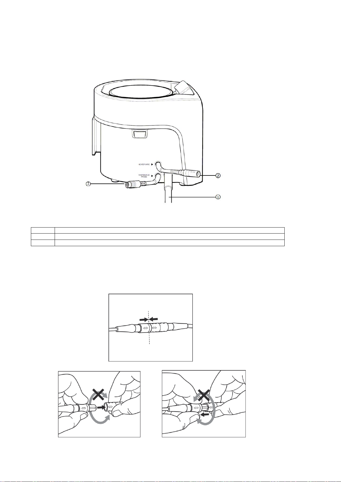
6.1Left Side View
6.2Left Side Panel Description
1
Power Cord Plug: to be connected AC power supply
2
Probe Connector : Temperature probe connecting port
3
Inspiratory / Expiratory Heater Wire Connector: Heated wire adaptor connecting port
NOTE: The power cord cannot be detached from the heater base. The power cord should only be replaced by an
approved engineer at the facility where such engineer is stationed.
Warning !
The Humidifier base cable should not be twisted during either connection or
disconnection.

Instruction For Use PMH7000 Version 2
Revision 03 23 July 2019 Page 15 of 20
7. Assembly with Breathing Circuit
As the preparation before use, the assembly process of breathing circuits is explained.
①Refer to the breathing circuits assembling illustration, assemble breathing circuits.
②Temperature probe or temperature probe connection
* Chamber outlet side temperature sensor: Connect to the chamber outlet side temperature probe connecting
port.
* Patient side temperature sensor: Connect to the patient side temperature sensor connecting port on the
breathing circuit.
③Heater wire connection
* Inspiratory side: Connect the connector of inspiratory heater wire extension cord or inspiratory/expiratory heater
wire extension cord to the inspiratory breathing circuit.
* Expiratory side: When the dual heater wire breathing circuit is used, use the inspiratory/expiratory heater wire
extension cord (optional item). Connect the connector to expiratory breathing circuit.
“Disposable Breathing Circuit Set-Up”
With Single Heater Wire
“Disposable Breathing Circuit Set-Up”
With Dual Heater Wire
Instruction For Use PMH7000 Version 2
Revision 03 23 July 2019 Page 16 of 20
8. Set up and Operation of the Humidifier base
(1)
Position the Humidifier base
Mount the heater base using appropriate bracket and make sure the heater base is placed lower
than patient position.
(2)
Placing Chamber
Before placing the chamber onto the heater base, check the base unit and
the chamber for damage.
a) Verify the heater base is clean and dry.
Then, place the chamber on the heater base and make sure it sits
properly on the housing as illustrated.
b) Ensure the water feed is correctly assembled and positioned.
Note: When using auto fill chamber, first place the chamber and then
connect sterile water pack.
Warning!
◇Do not fill with water hotter than 30C
◇Ensure that the water level in the chamber is correct before use. Failure to ensure correct
water level in the chamber at start-up could result in the under humidification of the patient
(see chamber IFU for details).
◇Do not exceed maximum water level.
(3)
Attaching heater wire and dual temperature probe
(a) Heater Wire
When using dual heated wire systems connect electrical adaptor 5601000 to the electrical adaptor
power outlet on heater base then connect the cloverleaf connector to inspiratory heated wire limb
and oval connector to the expiratory heated limb.
When using a single heated wire systems connect the electrical adaptor 5600000 to the electrical
power adaptor outlet on heater base then connect cloverleaf connection to the inspiratory heated
wire limb.
(b) Dual Temperature Probe
Connect the dual temperature probe to the heater base unit and insert the temperature sensors in
to the inspiratory limb ports as shown in diagram on page 15.
Warning !
◇Ensure the dual temperature probe is fully inserted into the port. Otherwise it could cause an
abnormal temperature reading.
◇Prevent sensor portion of the dual temperature probe from being in contact with the heater
wire.
◇Do not place dual temperature probe into the incubator or in any other heated place. It may
affect the temperature control.
(4)
Connect patient circuit to chamber
Set up for single and dual heated wire systems shown on page 15.
(5)
Connect power cord to AC wall socket
NOTE: Do not place the heater base on such a place where pushing in/out of the power cord plug is
disturbed.
(6)
Turn on gas supply equipment (Ventilator)
Connect the ventilator to the gas supply and turn on and carry out pressure testing applicable to the
ventilator protocol.
Warning !
Conduct pressure test of breathing circuit including chamber, before connecting the device to the
patient.

Instruction For Use PMH7000 Version 2
Revision 03 23 July 2019 Page 17 of 20
(7)
Turn on PMH7000 power button.
Heater base displays “88.8” and all LED’s are activated, alarm sounds for 2 seconds then will revert to
display the previous setting for temperature (patient side and chamber side). When it does not function
as described, turn off the power and remove heater base from breathing circuit and contact your Sales
provider for assistance.
A short alarm sound will be activated when Humidifier base is turned off.
Warning !
◇Do not use a heater base that does not properly function until probable causes are resolved.
◇Do not use device without gas flow. If gas flow is interrupted or significantly decreased, turn
off the device until the gas flow has resumed and stabilised.
(8)
Select desired mode
When “MANUAL” mode is selected, the factory setting is 37C at both patient side and chamber side.
This value can be changed by following instructions, please refer to Section 5.3.3 for how to change
the setting.
(9)
Connect to patient once the temperature has stabilized.
Humidification will start approx. 10 minutes later with the entire warm up period taking 30 minutes to
reach the setting temperature.
The portion physically touching to the patient (applied part) is a breathing circuit.
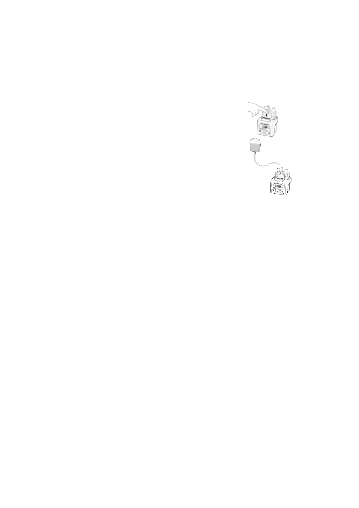
(10)
Remove chamber
Chamber can be easily removed by pressing the lock bar as
illustrated.
(11)
Exchange or replace the dual temperature probe
When the dual temperature probe is exchanged or replaced, be sure to turn off the power of the
Humidifier base. After exchange or replacement, re-activate the Humidifier base.
(12)
Safe Process to stop operation
Please follow below process for the operator to stop operation safety.
1) Remove the breathing circuit from the patient.
2) Press the power switch of the heater base for more than one (1) second to turn off the power.
3) Remove the power plug of the heater base from AC power supply.
4) Turn off the power switch of the gas supplying unit.
9. Maintenance & Repair
9.1Basic Checks
Visual inspection of the heater base and accessories should be performed monthly. Check the temperature probe sensors,
temperature sensor cables, all unit cables and connectors, and the power cord. Damaged items should be replaced if
necessary. For complete maintenance information, contact your sales provider.
9.2Dual Temperature Probe Check
It is recommended that the dual temperature probe be functionally tested on a routine basis (every 6 months) to ensure
that it is operating properly.
The following method is recommended:
1
Obtain a precision thermometer or other temperature measuring device accurate to within +/-0.5°C.
2
Place the thermometer (or equivalent device) and both of the temperature sensors into a container of
warm water (between 25°C and 45°C).
3
Allow time for equilibration of the thermometer and the dual temperature probe. Connect the dual
temperature probe to the heater base as recommended and turn the unit on. Compare temperature
readings. The display should be within +/-1.5°C of the thermometer. If not, probe should be replaced.

Instruction For Use PMH7000 Version 2
Revision 03 23 July 2019 Page 18 of 20
10. Reprocessing
PMH7000 humidifier bases and accessories should be cleaned, disinfected and sterilized according to the instructions in
the Cleaning, Disinfection and Sterilization Manual before use.
Components and
Parts
Material
Autoclave
Sterilization
Cleaning and Disinfectant
Solution
ETO Gas
@ 55°C
Dual Temperature
Probe
Housing: Polycarbonate
No
Yes
Yes
Base Unit
Housing: Polycarbonate
No
Yes
No
※ETO Gas Sterilization: Sterilization Time: 4 hours at 55°C, Aeration Time: min. 15 hours
Note:
CaviWipeTM (or equivalent) Disinfecting Towelettes to clean and disinfect all surfaces of the Humidifier base and Dual
Temperature probe.
Note:
Ensure that the heater plate surface is clean and free from excessive abrasions.
Warning ! DO NOT IMMERSE or STERILIZE main unit of PMH7000 Humidifier heater base.
Warning ! DO NOT STERILIZE or AUTOCLAVE the heater base unit.
11. Repair
Repair of the unit should be done only by a qualified technician.
Please contact your sales provider if there are any problems.
12. Disposal
Some authorities consider these materials are subject to special disposal.
Contact your local authority for the detailed information.
13. Trouble Shooting
The device has an alarm function, which shows any abnormal conditions during operation.
Each alarm shows the abnormal conditions by illuminating an LED on the front panel and sounding the alarm
Alarm sound can be muted by the mute button for 2 minutes, but the LED will keep flashing until the alarm condition itself is
removed.
LED Indicator
Alarm
Sound
Possible Cause
User Action
Patient Icon
(Abnormal high
temperature: Flashes
red)
Yes
1) Patient temperature≧set value
+2°C
2) No increase over +2°C in two
minutes after power on
Confirm first that there is no problem
on setting and breathing circuit. If the
alarm conditions are not restored, stop
using the unit and contact your sales
provider
Patient Icon
(Abnormal low
temperature :Flashes
yellow)
Yes
1) Patient temperature≦set value
-4C
Check dual temperature probe, and
restore the alarm condition.
Chamber Outlet Icon
(Abnormal high
Temperature: Flashes
red)
Yes
1) Chamber outlet
temperature≧set value+ 4°C
lasting for more than 20
minutes.
2) Chamber outlet temperature
reaches 10°C higher than set
temperature.
Confirm that there is no problem with
the setting. Review alarm conditions
and restore. If the alarm conditions are
not restored, stop using the unit and
contact your sales provider for repair.
Chamber Outlet Icon
(Abnormal low
Temperature: Flashes
yellow)
Yes
1) Chamber temperature≦set
value -4°C lasting for more than
20 minutes.
2) Chamber temperature reaches
10°C lower than the set
temperature.
Confirm the conditions of dual
temperature probe, and restore the
alarm condition.

Instruction For Use PMH7000 Version 2
Revision 03 23 July 2019 Page 19 of 20
Heater Wire Connection
Icon
(Heater wire abnormal:
Flashes red)
Yes
1) Heater Wire is not connected.
2) Heater Wire has come-off or
short-circuited.
1) Connect the heater wire firmly.
2) Replace the heater wire.
Temp Probe Connection
Icon
(Fault: Flashes red)
Yes
1) Dual Temp Probe is not
connected.
2) Dual Temp Probe has
disconnected or short-circuited
1) Connect the dual temp probe firmly.
2) Replace the dual temp probe.
Icon
(Unit Fault: Flashes red)
Yes
1) Chamber Temp doesn’t rise more
than 2°C for 30 minutes after
power-on.
2) Heater plate fault
3) Software memory error.
Remove the device from the breathing
system, and contact your sales provider
for repair.
All LED suddenly turn off.
No
Over heat protector is activated.
Remove the device from the breathing
circuit, and contact your sales provider
for repair.
The device is not
activated even though the
alarm condition is
restored.
Yes
Alarm state inter-lock is activated (It
is locked when alarm state
continues for > 10 minutes)
Turn off the device and restart it.
The device is not
powered on.
No
1) Device fused.
2) Heater base fault.
3) Overheat protector is activated.
1) Change the fuse.
2) Remove the device from the
breathing circuit, and contact your
sales provider for repair.
Temp panel is blank or
displaying “8.8.8.”or
other.
(Display is different
according to the state
when the power is on)
Yes
1) Failure of self-check
Remove the device from the breathing
circuit, and contact your sales provider
for repair.
* If an alarm state is left unresolved for 10 minutes, then the device displays “ ” and stops operating. The alarm
continues to sound intermittently. The Humidifier base requires turning off and on again to resume operation.
*The priority of each alarm condition is represented by the colour of the LED. Yellow indicates medium priority, RED is high
priority.
14. Compliant Accessories
The following accessories are available to order.
Part Number
Accessory Name
5600000
Electrical adaptor lead (Single heated wire system)
5601000
Electrical adaptor lead (Dual heated wire system)
7700000
Dual temperature probe assembly

Instruction For Use PMH7000 Version 2
Revision 03 23 July 2019 Page 20 of 20
Table of contents
Other Intersurgical Humidifier manuals

Popular Humidifier manuals by other brands


Skuttle Indoor Air Quality Products
Skuttle Indoor Air Quality Products 60-2, F60-2 Installation and operating insctructions

Aircare
Aircare EA1407 Use and care guide

Stulz
Stulz ENS Series Technical manual

Neptronic
Neptronic SKG3-110-1 N/P Installation instructions and owner's manuals

Fusic
Fusic FC-29 quick start guide

Weinmann
Weinmann CPAP 20e Description of the equipment and instructions for use