eyc-tech DPM11 User manual


www.eyc-tech.com
1
Contents
.......................................................................................2
...............................................................................................................3
..............................................................................................................3
..............................................................................................................4
........................................................................................4
5.1 Application Program Introduction ...................................................................4
5.2 Establish RS-485 connection ............................................................................4
5.3 Scan RS-485 connection...................................................................................7
5.4 Setting RS-485 ModBus Protocol ...................................................................11
5.5 Measurement Programming..........................................................................13
5.6 Linearity Computation ...................................................................................17
5.7 Export and Import Configuration...................................................................18
5.8 Device Information.........................................................................................19
5.9 Display and Data Log......................................................................................20
...................................................................................................24
6.1 Menu Flowchart.............................................................................................25
6.2 Abbreviation...................................................................................................27
............................................................................28

www.eyc-tech.com
2
⚫
⚫
⚫
⚫
⚫
⚫
⚫
⚫
⚫
⚫

www.eyc-tech.com
3
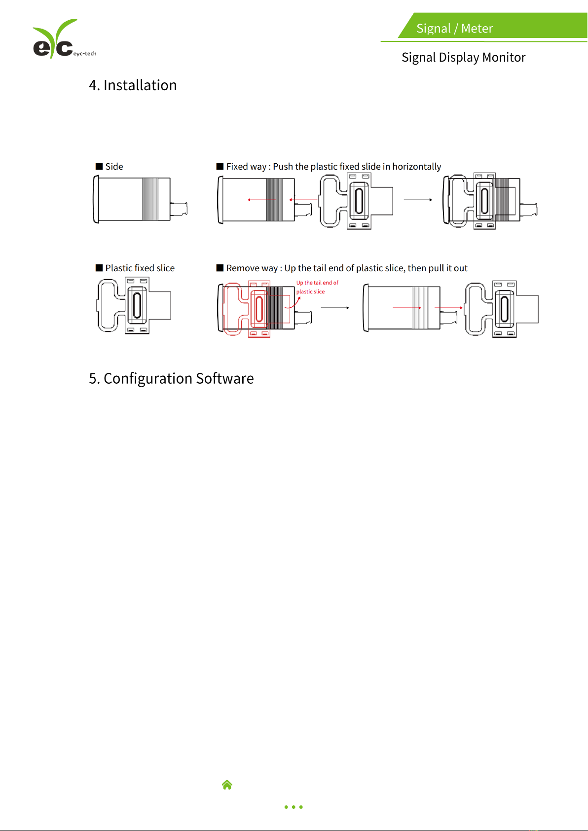
■Dimension
■Installation Dimension
www.eyc-tech.com
4
5.1 Application Program Introduction
User may download the configuration software on eyc-tech web site. Please
decompress the application prior to execute it. Operating System requirements:
above Windows XP. Other application program requirements: above Microsoft Office
2003. Hardware requirements: USB to RS-485 converter.
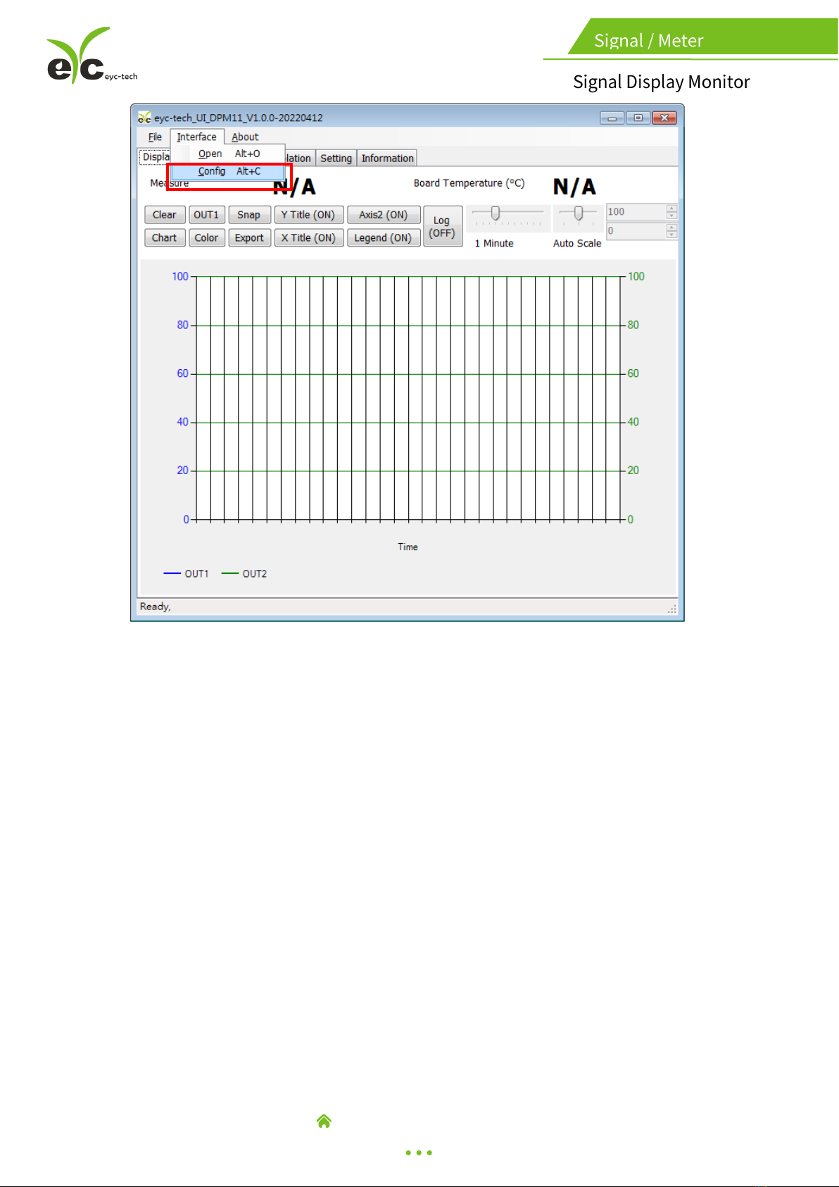
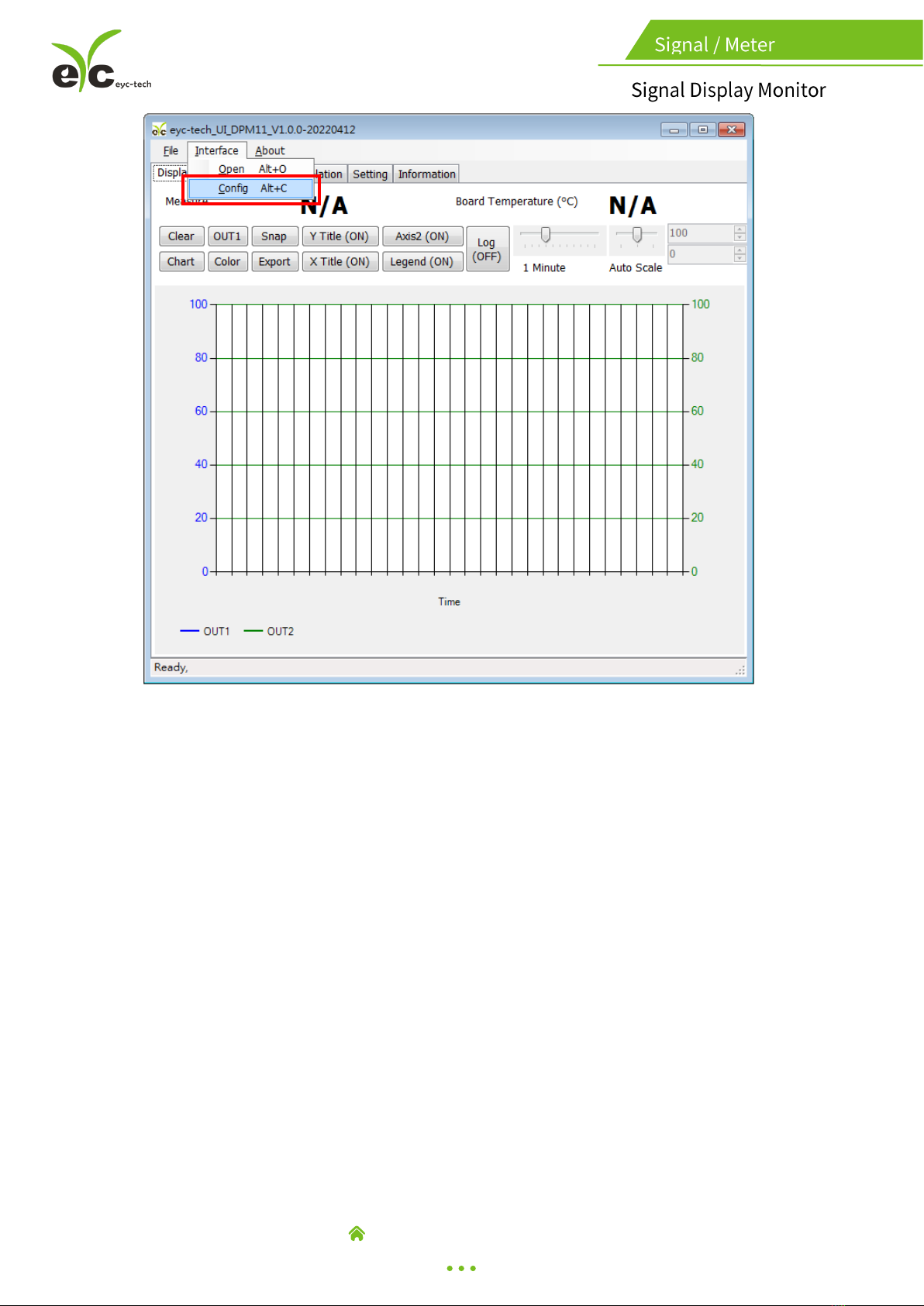
5.2 Establish RS-485 connection
1. Connect product to PC via RS-485 converter
2. Execute configuration software
3. Click "Interface > Config"
www.eyc-tech.com
5
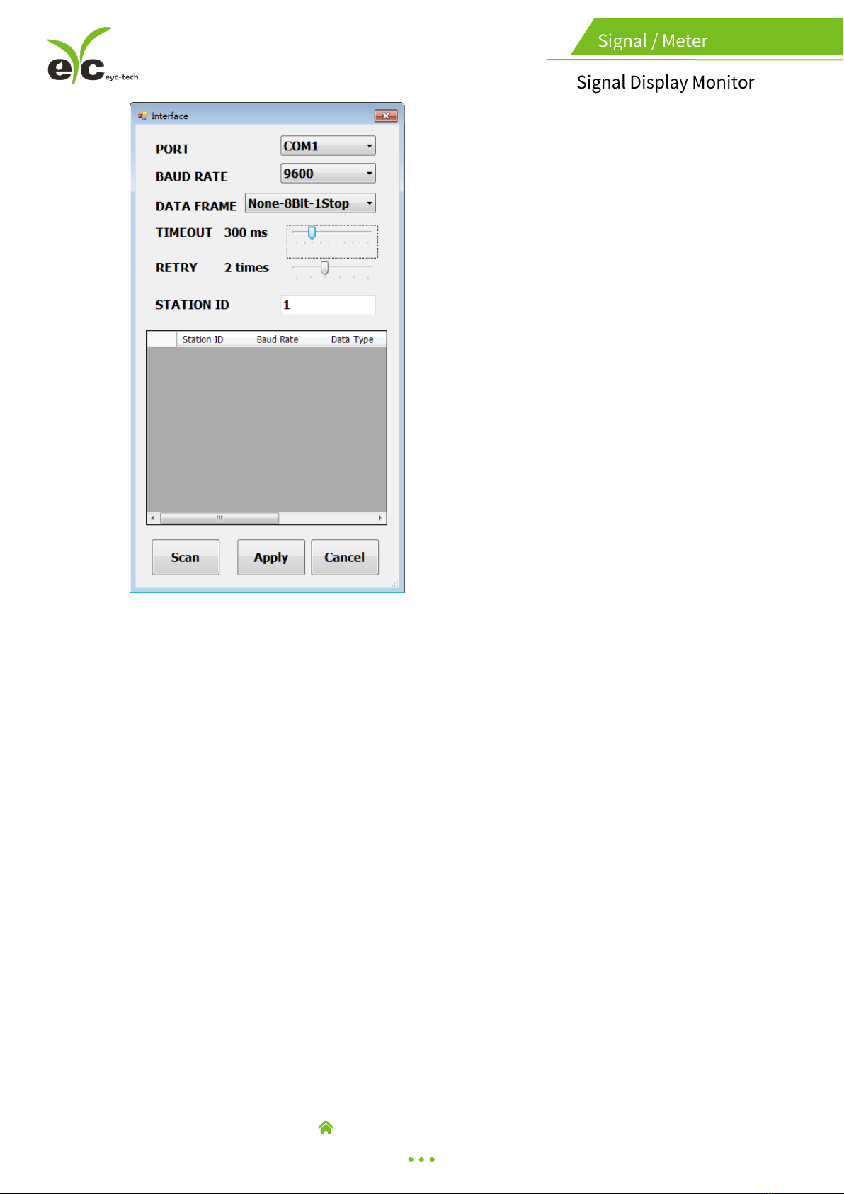
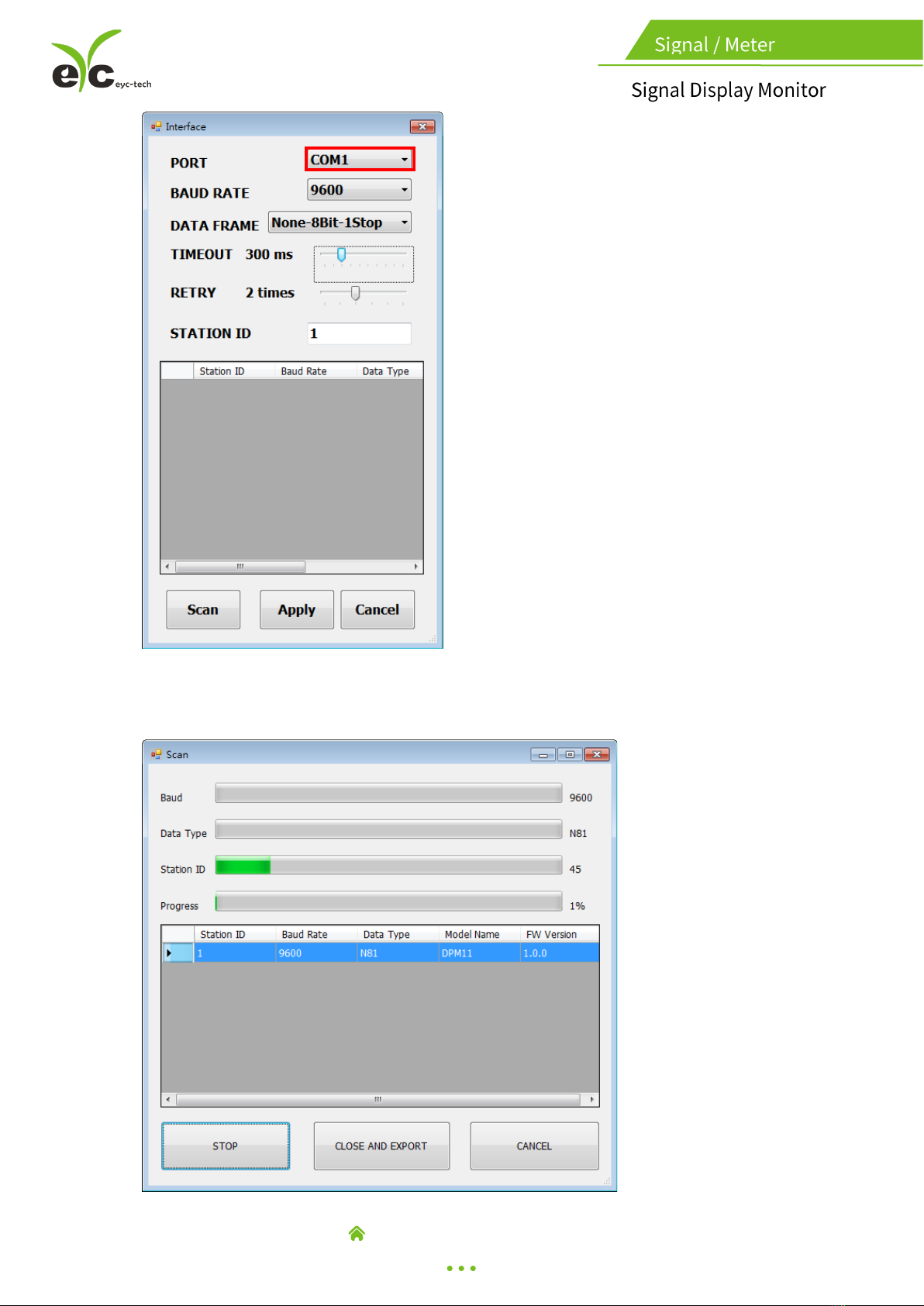
4. Select the corresponding values of com port as following :
a. Port: Please confirm the connection com port first
b. Baud Rate (DPM11 default 9600)
c. Data Frame (device default None Parity Check, 8 data bits, 1 stop bit)
d. Response Timeout (default 300ms)
e. Retry, trial cycles if communication error (default 2 times)
f. Station ID (default 1)
www.eyc-tech.com
6
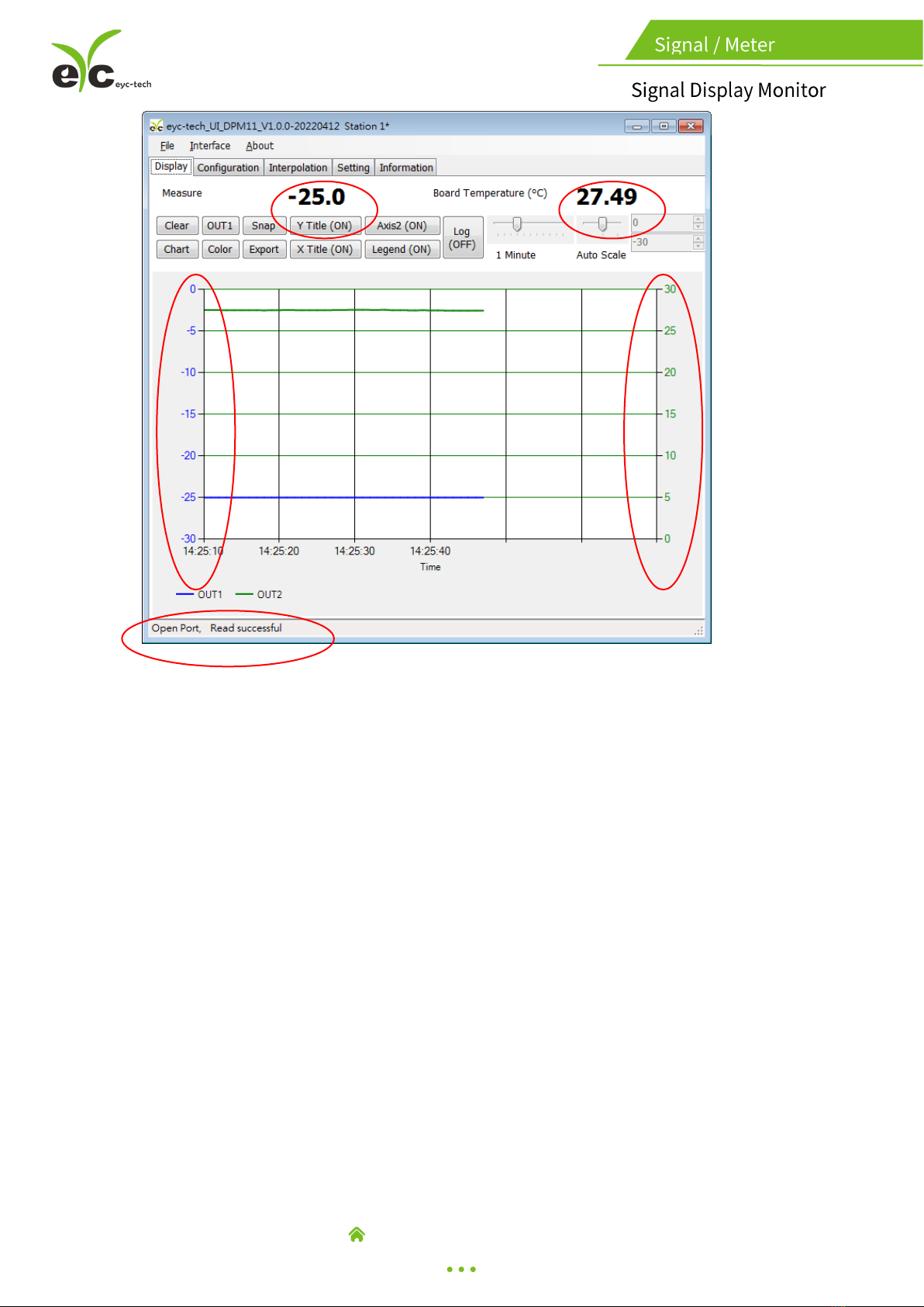
5. Click "Apply"
6. Connect successfully
a. Show value and trend chart of the measurement
b. Show value and tread chart of device mcu temperature
c. Show "Open Port, Read successful"
a.
b.
c.
d.
e.
f.
www.eyc-tech.com
7
5.3 Scan RS-485 connection
※Use scan function to connect when forgetting the connection information or
having more facilities.
1. Connect the product to PC via RS-485 converter
2. Execute configuration software
3. Click "Interface > Config"
a.
c.
a.
b.
b.
www.eyc-tech.com
8
4. Select the corresponding values of com port as fallowing:
www.eyc-tech.com
9
5. Click "Scan" to execute connection facilities
6. Scan connection facilities and set up
a. Select Station ID
b. Click "CLOSE AND EXPORT"
7. Click "Apply"
a.
b.
Table of contents


