EYELA CA-1330 User manual

Cool Ace
CA-1330
Low Temperature
Circulator Instruction
Manual
R00
Tokyo Rikakikai Co., Ltd.
This instruction manual is designed to use the product safely with keeping its best
performance.
Please keep this manual in a place easily accessible to every users.
IMPORTANT Be sure to read “Safety precautions” before use.

FORWARD
Thank you very much for your kind patronage of EYELA.
Get to know your EYELA products, but before using, to be sure to read this manual well.
EYELA cannot be held responsible for the malfunctions resulting from the use of EYELA
Products other than as specified in this manual.
WARRANTY
EYELA products are warranted against defects in materials and workmanship for a period
of year following the date of shipments.
EYELA will make repairs or replacements free of charge upon return to the factory,
Transportation paid, of the defective item except following cases.
This warranty does not cover finishes nor dose it cover damage resulting from accident,
misuse, abuse, tampering, servicing performed or attempted by unauthorized service agency.
The consumable parts are not warranted even if they are within the warranty period.
Manufacturer : Tokyo Rikakikai Co., Ltd.
TN Koishikawa Bldg.
1-15-17 Koishikawa, Bunkyo-ku, Tokyo 112-0002 Japan
Pone: 81/3-6757-3378
Fax: 81/3-3868-6571
Web site: www.eyelaworld.com
LIABILITY DISCLAIMER
Liability to Tokyo Rikakikai Co., Ltd. For any defect in this instrument is limited to the
Invoiced price of the defective instrument.
Tokyo Rikakikai Co., Ltd. Has no control over the set up, use, connection to other
Equipment, or data generated by means of EYELA products.
Therefore in no event shall Tokyo Rikakikai Co., Ltd.be liable for any incidental or
Consequential damages , losses, or liability which may result from improper use of its
Products, either in connection with other equipment or in the generation, reporting, or
Application of data and results.
SERVICE
1. Before asking our service agency, check your instrument again with trouble
shooting on this manual.
2. We shall repair the instrument subject to WARRANTY CLAUSE
3. Ask our authorized service agency for repairing.

To ensure the safety, this manual defines the information
on such matters as requiring particular care in the safety
as follows in terms of the importance and risk and attaches
the alert mark and signal word.
It is recommended to follow the instruction to ensure the
safe use of the product.
IMPORTANT SAFETY INFORMATION
1. Warning signal word
Alert mark
Signal word Definition
Wrong handling is assumed to cause the possibility of the death or heavy
injury of the user.
Wrong handling is assumed to cause the risk of injury of the operator or
physical damages.
Warning
Caution
このイメージは、現在表示できません。
We have undertaken thorough verification concerning the possible occurrence of risk in the course of use
of the product, but prediction of all and every kind of risk is extremely difficult. Namely, cautions contained
in this manual are not necessarily all of possible risks.
However, if the product is operated according to the procedure described in this manual, the safe
operation and work is ensured. Be sure to pay utmost care during handling of the product to prevent
accident or failure of the product.
The unit is not of an explosion-proof construction.
Take extreme care for handling flammable samples or
organic solvents not to spill them.
The unit uses H2 gas and shall be installed and
operated in a draft chamber.
This product will be used with part it is hot because of
its functions and features.
This product includes glass parts which might break
and cause personal injury or other accidents if handled
inappropriately.

※If damaged and illegible, be sure to change the warning
label to the new one.
Send the request for the new label to us.
For particularly important warning instructions, the warning
label is provided to the product main body.
The labelling position is shown below.
When using the product, be sure to pay due attention to the
description of the warning.
2. Warning Display on the Product
CAUTION
Do not touch the
cooling fin with your
bare hands.
It may cut your fingers.
Fire hazard
WARNING
Use extreme caution
when using Inflammable
and ignitable solvent.

Contents
1. For safe operation of the unit 1
2. Product overview
2-1 Applications 2
2-2 Specification 2
2-3 Data(reference)3
2-4 Name of parts 4
3. Names and functions of operating portion
3-1 Control panel 5
3-2 Safety・alarm features 6
4. Installation
4-1 Installation environment 8
4-2 Installation condition 8
4-3 Installation 9
4-4 Using the bracket to prevent
overturning 11
4-5 Utility connection 12
Introduction
Caster holder
Bracket to prevent
overturning
Hose nozzle Valve for adjusting
flow volume
Item Qty
1Main unit 1
2Valve for adjusting Flow volume
( R3/8 x Rc3/8) 1
3Hose nozzle (R3/8×O.D.Φ10.5 )2
4Caster holder 2
5Bracket to prevent overturning 2
6Instruction manual 1
Thank you for purchasing our
product.
This instruction manual explains installation,
operation, troubleshooting, maintenance and
inspection, and discarding procedures for the
Always read this manual before use to ensure
familiarization of the product.
Low Temperature Circulator
[Cool Ace]model: CA-1330
Check the type and quantity of items before setting up.
Details of items in the package
5. Operation
5-1 Preparation 13
5-2 How to operate the unit 16
5-3 Operation in the user setting mode 21
6. Consumption parts/Optional accessories 23
7. Troubleshooting 24
8. Maintenance・checkup
8-1 Operation test for residual current device 26
8-2 Cleaning and caring the product 26
9. Disposal of the product 28
10. After-sale Services 29

-1-
Hatched portions (top and sides)
Heated to high temperatures.
1
The top and exhaust port be heated to high
temperatures during operation.
Do not touch them.
When used under a table at the room temperature of 30℃or more, the top
and sides of the product may be heated with exhaust heat to high
temperatures.
Do not touch them to prevent burn.
For safe operation of the unit
This product is not designed with explosion-proof structure.
Use with extreme caution when handling it.
WARNING
Use with extreme caution when handling
inflammable or combustible solvent.
If you leave inflammable or combustible solvent (ethanol and etc.)
at room temperature or higher (lower for some solvent),
it may evaporate and catch fire with some fire sources, and cause
a fire and explode. Ventilate the space well before use.
CAUTION Do not touch cooling fin with bare hands
while performing maintenance work.
Edgy fin may cut your fingers.
Do not touch cooling fin with
bare hands.
CAUTION

-2-
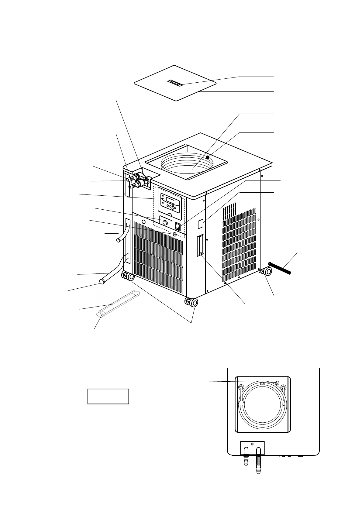
This is a cooling water circulator, which cools water
by means of the refrigerator inside the bath and
circulates cooling water by means of the circulation
pump to the outside to cool the evaporator, reactor,
the heating portion of various mechanical units
This product is of a low-floor type and can be stored
in a space under a table.
This is capable of cooling two 1L type evaporators
simultaneously.
2-2 Specification
※The performance is for the room temperature of 20℃, the rated supply voltage, 50 Hz, and the no-load state.
※1 For the room temperature of 35℃, the set temperature range can be up to -10℃.
※2 The cooling capacity is ±10%of the listed capacity.
※3 The circulation capacity is ±10%of the listed capacity.
※4 Power cord and other projections not included
2
Product name Low temperature circulator (Cool Ace)
Model CA-1330
Circulation system Circulation for sealed system
Performance
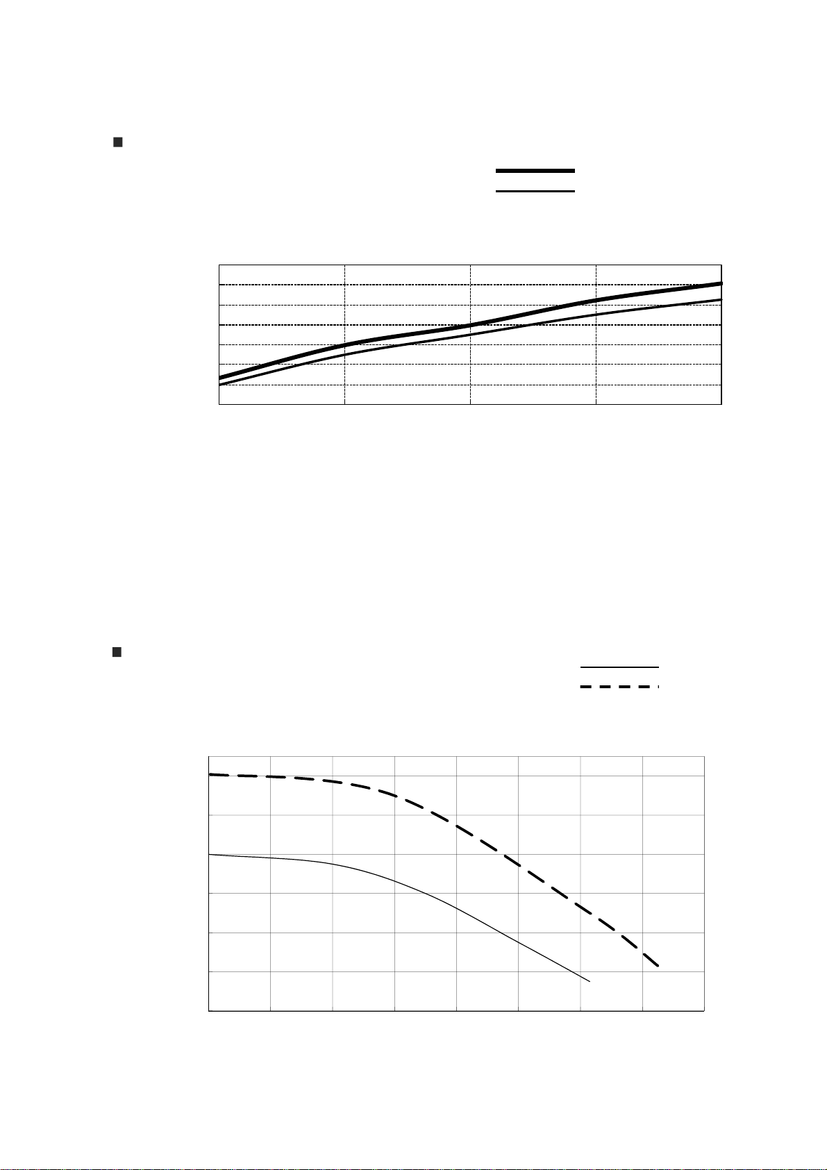
Temperature control range ※1-20℃~+20℃
Accuracy of temperature control ±2.0℃~
Cooling capability※21050Wat10℃
External circulation Capability※3
(50/60Hz) Max. flow volume 12/14L/min
Max. lifting height 9.5/13m
Functions
Temperature control system Refrigeration unit, ON-OFF control
Temperature setting・display Sheet key digital setting , LED digital setting(minimum digit:1℃)
Safety features Residual current device・excess current breaker , Self-diagnosis function
of the temperature controller, Over load relay holding circuit, Protection
timer for refrigeration unit, Thermal protector for circulation pump, High
pressure switch of the refrigeration unit
Optional parts External sensor terminal, communication terminal(for NVC3000)
Configuratio
n
Temperature controller Electronic digital setting・digital display
Temperature sensor Pt sensor (Pt100Ω)
Refrigeration unit・refrigerant Air cooling type 650W・R407C
Cooling coil Copper(Nickel coating)
Spec.
External circulation nozzle External diameter:10.5×Bore diameter: 7(R3/8)
Bath material, dimensions and
capacity SUS304, W270×H270×D175[mm], (MAX12.8L, liquid capacity
approx.10L)
Operating ambient temperature 5~35℃
Dimensions (main unit)(mm)※4 W460×D430×H570
Mass Approx. 48kg
Power input・rated power 5A AC220V±10% 50/60Hz
Operation presser max. 2.55MPa
Pollution degree 2
Over voltage category Ⅱ
Operation at a terrestrial altitude Max2000m above sea level
2-1 Applications
Product overview
Never attempt to disassemble or modify the
product.
Do not use the product for any purposes
other than those specified.
Modification or use for purposes other than those
specified may lead to an electric shock or a
malfunction.
Warning

-3-
0
200
400
600
800
1000
1200
1400
-20 -10 0 10 20
Liquid temperature (℃)
Cooling capacity)
Cooling capacity curve
Conditions ・220V 50Hz
・Circulation rate maximum
Room temperature at 20℃
・The cooling capacity is ±10%of the listed capacity.
・The capacity shown above is for the unit proper.
・The cooling capacity is degraded by about 14% when the unit is installed under the table as
compared to the case of installation outside the range of table.
The cooling capacity is degraded by 26% at -20℃.
※Measurement conditions for installation under the table: The unit is covered for 5 cm in the
backside, 3 cm on the top, 40 cm on the right side, and the left side.
Pump circulation capacity
Conditions ・220V
・Circulation solution Water
・Room temperature 20℃
・Nozzle outside diameter Φ10.5mm
50Hz
60Hz
・The circulation capacity is ±10%of listed capacity.
・The listed capacity is for the unit proper.
2-3 Data(reference)
Installed outside the of table
Installed under the table
Lift m
Flow L/min
2
4
6
8
10
12
14
0 2 4 6 8 10 12 14 16

-4-
2-4 Name of parts
Strainer
Top
Operation panel
Power cord
Cooling coil
Cooling-water
circulation bath
Drain hose
Drain plug
Bath cover
Caster (with stopper)
Ventilation
cover
Circulation WATER-OUT
nozzle outside the bath
Circulation WATER-IN
nozzle outside the bath
Earth leakage・
overcurrent breaker
Water level gauge
Flow control valve
Water pan (through hole)
Caster (without
stopper)
Drain cover
Power switch
Front
Bath grip
Grip
Ventilation
cover grip
Drain cover grip
Water pan drain hose
Comm. terminal※1
※1 This product can be connected with the vacuum controller, Model NVC-3000.

-5-
Run
Stop
Pump
Alarm
Refrigerator
Pump
Set
PV
Run/Stop
℃
3-1 Control panel
①
Names and functions of operating portion
3
②
③
④
⑤
⑥
⑦
⑧
⑨
⑩
⑪
№Name Function
①Power switch Turns on and off the power. ※Interlocked with ON/OFF of the service
outlet.
②Alarm LED Lights up when alarm happens.
③Circulation pump LED Lights up when turning on circulation pump switch.
④Refrigeration unit LED Lights up when turning on refrigeration switch.
⑤Control status indicating
LED Lights up when the control is on.
⑥Display Displays temperature or alarms.
⑦Run/Stop Key Starts or stops the control.
⑧ ▲ Key Increases the value of temperature in increments of 1℃by one
press at the temperature setting display. The continuous
pressing of key increases the value continuously.
⑨ ▼ Key Decreases the value of temperature in decrements of 1℃by one
press at the temperature setting display. The continuous
pressing of key decreases the value continuously.
⑩Set Key Changes the display of setting the value and measured value.
At the setting value display, the changed setting value is decided.
At the alarm display, the alarm display is cleared and it changes
to the normal display.
⑪Pump Key Turns on or off the circulation pump.

- 6 -
Safety features
3-2 Safety・alarm features
This product is equipped with the following safety features and alarm features.
If you face any trouble, please refer to “Troubleshooting" on page 24 and follow the instruction.
Safety device Operation Reasons why the device works.
Residual current
device Power is turned off. ・Electric leakage hazard occurs, or excess current flows.
High-pressure
switch for
refrigeration unit
Pressure rises abnormally while the
refrigeration unit is operated, and
alarm LED lights up, which stop
running refrigeration unit.
・Ambient temperature exceeds 35℃.
・Heat load was too heavy for cooling capability, which
made the temperature in the bath rise.
・Dirt adheres to air filter.
・Fan for refrigeration unit does not work.
Protection function
for refrigeration
unit’s over load
Refrigeration unit operates with
over loaded (over heated), which
made Alarm LED light up and stop
refrigeration unit.
・Refrigeration unit started up with over loaded.
・Low supply voltage
・Ambient temperature exceeds 35℃.
・Heat load was too heavy for cooling capability, which
made the temperature in the bath rise.
・Dirt adheres to air filter.
・Fan for refrigeration unit does not work.
Thermal protector
for circulation
pump
Circulation pump performs over
heat operation and stops operation.
(Recovers when the pump is
cooled
down.)
Over heat operation of circulation pump
・Circulation liquid has high viscosity.
・Foreign substance is sucked in.
・Ambient temperature exceeds 35℃.
・Piping resistance is high.(Valve is closed and etc.)
Self-diagnosis
function for
temperature
controller
Temperature controller gets in
Abnormal status, which made
alarm light up and stopped all the
controls.
The device recovers naturally if the
trouble can be sorted out.
・Temperature controller is in abnormal status because of
noise and etc.
・Ambient temperature exceeds 35℃.

Alarm features
7
Alarm name Alarm display and operation Cause
Operation conditions
・Temperature sensor is disconnected or
short-circuited.
Sensor alarm
・Alarm is displayed
・Alarm LED illuminates
・The control is stopped and the
circulation pump stops.
℃
Alarm
Pump
PV
LED ON
Refrigeration unit
alarm
・Alarm message blinks.
・Alarm LED illuminates
・The control is stopped and the
circulation pump stops.
℃
Pump
PV
Blinks
Operation conditions
・Refrigeration unit high pressure switch
works or the refrigeration unit overload relay
works.
Canceling the alarm
・The alarm can be canceled with the [Set]}
key when the refrigerator high-pressure
switch or the refrigerator overload relay is
reset.
℃
Pump
PV
Alternate display
of the alarm and the
measured temperature
Temperature
Upper limit alarm
・Alternate display of the alarm and the
measured temperature
・Alarm LED illuminates
・The control is stopped and the
circulation pump stops.
Operation conditions
・The temperature around the sensor exceeds
the upper limit.
Canceling the alarm
・Alarm can be cancelled by pressing the
Set key with the measured temperature
lower than the set upper limit.
※Default upper limit:+80℃
※The user can change the set upper limit.
(Refer to P.21, 5-3. Operation in the
User Setting Mode.)
℃
Pump
PV
Alternate display
of the alarm and the
measured temperature
Temperature
lower
limit alarm
・Alternate display of the alarm and the
measured temperature
・Alarm LED illuminates
・The control is stopped and the
circulation pump stops.
Operation conditions
・The temperature around the sensor exceeds
the lower limit.
Canceling the alarm
・Alarm can be cancelled by pressing the Set
key with the measured temperature higher
than the set lower limit.
※Default upper limit:-50℃
※The user can change the set lower limit.
(Refer to P.21, 5-3. . Operation in the
User Setting Mode.)
Alarm for recovery
from power failure
・Alternate display of the alarm and the
measured temperature
・Alarm LED illuminates
・Power failure recovery function
ON … Recovery to the state
immediately before Power OFF
Power failure recover function
OFF…Control, pump circulation OFF
℃
Pump
PV
Operation conditions
・During the temperature control operation
with setting Power Failure Recovery
function, [On] or [OFF], the power was off
and switched on.
Canceling the alarm
・The alarm can be canceled with the [Set]
key.
※The user can change the ON/OFF
selection of power failure recovery
function. (Refer to P.21, 5-3. Operation
in the User Setting Mode.)
Alarm
Alarm
Alarm
Alarm
Alternate display
of the alarm and the
measured temperature

-8-
4
The exhaust temperature of the
unit may exceed 60℃in certain
cases.
To keep the best performance of the product, leave
the space between product and wall, ceiling plane.
The distance between the product and wall, ceiling
plane must be longer than the one mentioned in the
right picture.
※Keep a distance of 3 cm or more between
the unit backside and the wall surface and 3
cm or more between the unit top and the
ceiling.
※The unit can be used with one of left or right
side blocked. In such an event, be sure to
keep a distance of 40 cm or more between
one of unit sides and the wall surface.
(※ For use at the room temperature of
30℃or below, the unit can be used if a
distance of 10 cm is secured between one
side and the wall surface.)
※Install the unit so that its front (with a
ventilation port) does not come under the
table.(See the table on P.10)
※With the unit installed with its side covered
40 cm under the table, the cooling capacity
is degraded by maximum 14% as compared
with the case of installation outside the
range of table.
At the -20℃setting, the cooling capacity is
degraded by maximum 25%.
CAUTION
CAUTION
4-2 Installation condition
4-1 Installation environment
Installation
●No direct sun light
●Ambient temperature must be from 5 to 35℃.
●Well-ventilated.
●No inflammable solid or liquid or gas around the unit.
●No dew condensation
●Lesser humidity and no dripping on the unit.
●Lesser dust
●Level and stable
(Check the weight of the product during operation.)
●Indoor use only
Do not place anything on top of the
product.
CAUTION
Keep enough space around the unit.
Be careful about the environment of
installation. In particular, pay due
attention on the location, air
conditioning, and ventilation.
CAUTION
Since air-cooled type refrigeration unit is
equipped with this product, heat is exhausted from
the unit.
Select the installation site that can be ventilated
well so that the ambient temperature won’t rise
because of exhausted heat. Using the product in
high ambient temperature may worsen the
operation efficiency or cooling capability. Also,
refrigeration unit will be hot and operate under
high pressure, which may cause malfunction.

-9-
4-3 Installation
(1) Unlock the lock of the stopper of the caster.
If you press and lift the lever of caster’s stopper,
lock can be unlocked (Only front two casters
have stoppers).
(2) Move the unit to the installation site.
※Traveling over steps or surface irregularities may cause
extreme impact on the casters, possibly resulting in
damage. To avoid such an event, lift up the product for
traveling.
Traveling of the unit with refrigerant left in it requires
utmost care because the adequate water level is close to
the top of the unit. In such an event, water may overflow
during traveling.
(3) At installation site, lock caster’s stopper.
Holding down the lever of caster can lock the
stopper.
(4)Put supplied caster holders (2 pieces) into the
caster to fix.
These holders fix and prevent the caster from
rotation and swiveling. Caster holder
Caster
FREE
LOCK
Caster
stopper
CAUTION
Install the unit with its
front matched to the
broken line.
3cm or more
CA-1330 Approx. 48kg
Be careful during transport of the
product because it is heavy.
CAUTION
As refrigeration unit is equipped with the main
unit, do not lay down the product or incline it
more than 15°when carrying.
Do not incline the main unit more
than 15°
Caster(With stopper : Front wheel)
Caster (No stopper
attached :Back wheel)

- 10 -
Typical installation
Good No good
※Both right and left sides not to
be blocked
※Right and left sides blocked
※Both sides and backside blocked
※Sides and backside blocked
※Backside blocked
※Unit front coming
under the table
5cm or more 40cm or more
5cm or more
5cm or more
40cm or more
40cm or more
※3 cm or more secured between
the unit top and the ceiling.る
※3 cm or more secured between
the unit top and ceiling
※3 cm or more secured between
the unit top and ceiling

- 11 -
4-4 Using the bracket to prevent overturning
This bracket to prevent overturning is for fixing as an earthquake countermeasure and for securing the
unit for assembling.
Fixing is made by means of bolts applied to the unit and floor surface.
※Foundation bolts (for M10) are to be provided by the customer. The bracket has not been
attached before shipment.
Fixing with foundation bolt
※Secure the bracket to prevent overturning to the unit in a direction
shown in the figure.
Hole for
foundation bolt
(12mm)
Unit mounting hole
Unit mounting slots
Unit fixing screws

4-5 Utility connection
12
Inappropriate connection may cause a fire or
electric shock hazard.
Check the voltage, phase and
capacity of power source before
connecting.
WARNING
Over-current may cause cable burn, fire.
Do not use the branching
socket or table tap.
WARNING
Model Required power source
Voltage Capacity
CA-1330 AC 220V
Single phase 15A
CAUTION
Remove the dirt on the grounding
adapter,
outlet and mains connector.
Dirt on these parts may cause tracking or fire.
WARNING
The unit must be earthed.
Without grounding the unit, the product may
cause electric shock hazard.
(1)Check the voltage, phase and capacity of
the power source. Required power source
is as shown in right table.
(2)Check the type of outlet at the installation site.
(Do not connect the mains connector yet.)
If the outlet has earth terminal, mains
connector can be connected.
Length Thickness
(O.D.) Mains plug Cable
cross-
sectional
area
2.8m About
9mm 3-pronged
with earth
terminal
1.5mm2
Do not use branching socket when connecting to
power source.
* The grounding adaptor is not supplied with this unit.

- 13 -
5-1 Preparation
Use the circulation refrigerant that does
not affect the circulation route material
inside the unit.
CAUTION
Materials of the system interior include copper
(plating), stainless steel, brass (plating), Teflon,
silicon rubber, Noryl resin, chloroprene rubber,
Duracon, and polypropylene. Always use the
circulation solution that does not affect these
substances. By nature, pure water with higher purity elutes the
material of parts in contact, and if used, may cause
troubles such as delamination of paints, pump failure,
etc. Always use either tap water or softened tap water.
CAUTION
Do not reduce the piping size or
elongate the hose for use.
Do not use the pure water
CAUTION
Operation
5
When using hose join that is not supplied with the
product, the bore diameter of the joint must be larger
than 6mm. Use the hose at appropriate length.High
piping resistance causes decrease in the circulation
rate, which in turn causes failure of sufficient mixing
inside the bath. In such an event, the cooling
efficiency may decrease and the temperature
distribution inside the bath may become
unsatisfactory. Excess load may also be applied to
the refrigerator and the circulation pump, resulting
in failure.
CAUTION
WARNING CAUTION
Use extreme caution when using
combustible or inflammable
solvent.
If you leave combustible or inflammable solvent
(ethanol and etc.) out at room temperature or higher
(lower for some solvent) , it may evaporate and catch
fire with some ignition source, and cause explosion.
Ventilate the space well while using these solvent.
Do not conduct closed operation or
idling of circulation pump.
These operation may cause malfunction. Lead the hose around while taking care
not to allow it to be buckled or crushed.
Buckled or crushed hose may cause faulty cooling of
a counterpart unit or hose disconnection from the
nozzle, resulting in water leakage.
90゜Elbow
Valve for adjusting
flow volume
Hose joint
Nozzle(WATER OUT)
Nozzle(WATER IN)
Connecting pipe and hose
(1) Screw hose joint, flow amount controlling valve
hose joint into the unit.
(The seal tape is wrapped around the
hose joint and the valve. )
Nozzle(WATER OUT)
Nozzle(WATER IN)

- 14 -
(2) Connect hose (bore diameter: 9mm) to
external circulation discharging nozzle,
water-in nozzle, device for cooling
(closing-up style) and etc. Fix the hose
tightly with hose band so that it won’t be
slipped.
(Hose and hose band are not included.)
※Use the hose that has appropriate
withstanding pressure, heat-resistant and
appropriate material, which can not be
soaked in solvent.
Also, the material of hose should not be
bended or squashed when pulling it around
the unit.
Drainage from drain hose for tray
※Container to catch discharged
water is not included.
Check the tray regularly. Pull the handle of drain
cover softly and pick up the cover to remove it.
Then, drain away the water after removing the
stopcock of the drain hose for tray.
Drain hose for tray
Drain stopcock for tray
Using the unit as an stand-alone low temp. bath
When using the unit as a stand-alone low temp. bath,
Connect bypass hose to discharge and water-in
nozzle. If you turn on circulating pump switch in
this status, stirring will be performed in the bath
and cooling capacity will be worsened.
Fix the hose tightly with hose band so that it won't be
Slipped ( hose and hose band are not included ).
Bypass hose
Drain cover

- 15 -
※Use the antifreezing solution when the unit is
to be used at +5℃or below. Note that ethylene
glycol
or Nybrine, if used, may have the higher viscosity
within the low temperature range, resulting in
reduction of the circulation amount or activation of
the safety device of circulation pump. Never use
them at 100% concentration.
(Be sure to confirm the temperature range of
antifreezing solution because the freezing
temperature
differs depending on the concentration.)
※The use of water at the set temperatures around
+5℃may cause freezing of the cooling coil,
resulting in deterioration of the cooling capacity.
※Make sure that there’s no foreign substance in
circulation liquid, which will cause malfunction.
(2)Make sure that water-out valve for adjusting flow
volume is closed.
(3)Set the bath cover on the main unit.
Connecting mains plug
Do not use the pure water
Always use either tap water or softened tap
water.
By nature, pure water with higher purity elutes
the material of parts in contact, and if used,
may cause troubles such as delamination of
paints, pump failure, etc.
Filling the cooling water
(1)Confirm that the drain plug has been applied and
remove the bath cover/ Fill water.
Water level in the
cooling water bath
Fill water till the cooling
coil is fully immersed.
Cooling coil
Water level gauge
Fill so that
the water
level cover
within a rage
shown with
arrows.
Make sure that power switch is turned off and
plug the mains plug into AC outlet.
Valve for adjusting flow volume
Close
Open
WATER IN
WATER OUT
Do not move the unit while liquid is in the bath.
This product is not in waterproof structure.
There is fear of electric shock and
an unexpected accident.
Table of contents
Other EYELA Fan manuals
Popular Fan manuals by other brands

Nuaire Group
Nuaire Group AXUS Series Installation and Maintenance

Lasko
Lasko 4820 Instructions and operating manual

Chore-Time
Chore-Time Hyflo Assembly manual

ProKlima
ProKlima FN-110192.1 instruction manual

Minka Group
Minka Group F516L-WH Instruction manual warranty certificate

Koncar
Koncar VARSK ABC Series manual