EYELA Cool Ace CA-2610 User manual

Tokyo Rikakikai Co., Ltd.
This manual includes important information concerning the maintenance of the
functionality of the product and safety use.
Please keep this instruction manual within easy reach of yourself whenever using the product.
Important
CA-2610
CA-2610 S
Instruction
Manual
Cool Ace
R00
Low
Temperature
Circulator
Please read carefully especially on
“Safety precautions” before use.

Safety precaution
When using this product, mishandling and
inflammable and combustible solution may cause
unexpected personal injury or accident. Also, due to
its function and characteristic, operation under high
temperature may worsen the function and cause
breakdown. However, if your have proper
information before use, you can avoid almost all
these troubles.
Therefore, this manual categorizes the level of
importance and danger as below with alert mark
and signal word. Please follow the instructions
and use the product safely.
1. Signal word for warning
Though we are trying to look into conceivable risk of using the product, it is very difficult for us to
expect all of it. It means that all the instructions in this manual do not cover all the types of risks that
may be caused by the product. However, if you follow the instructions, you surely can handle and
operate the product safely. Please use extreme care when handling this product and try to prevent
all the potential accidents and mechanical failures.
Alert mark
Signal word Definition
Mishandling the product may cause serious personal injury or
loss of life.
Mishandling the product may injure users or cause property
damage.
WARNING
CAUTION

* If you have trouble reading warning label because of
damage, please change the label and attach the new one.
Please contact us if you require new label.
2. Warning display on the product
For high priority danger, warning label is attached on the machine body.
The position of the label is as below. Please read the instruction carefully
whenever you use the machine.
Flammable warning
Warning
Use extreme care when
handling inflammable or
combustible solution.
The fin may hurt
yourself.
Caution
Do not touch cooling
fin with bare hands.

6. Options
6–1 Sealing up cover
(Circulation to open system) 22
6–2 High pressure pump 23
6–3 Pressure switch 24
6–4 Flow amount switch 27
6–5 External sensor and
output lead wire 30
6–6 Lead wire
for remote operation 31
7. Troubleshooting 32
8. Maintenance and check-up
8–1 Operation test
of electric leakage breaker 35
8–2 Cleaning and
caring the product 35
9. Disposal of the product 37
10. After-sale service 38
11. Consumable/Replacement
Parts/ Optional Parts List 39
Thank you for choosing the product of
1. Safety precautions 1
2. Outline of the product
2–1 Use application 2
2–2 Specification 2
2–3 Cooling capability curve 4
2–4 Circulating capability 4
2–5 Name of each part 5
3. Name and functions of operation portion
3–1 Control panel 6
3–2 Safety / Alarm function 7
4. Setup
4–1 Setup environment 10
4–2 Setup conditions 10
4–3 Setup 11
4–4 Utility connection 12
5. Operation
5–1 Preparation 13
5–2 How to operate 15
5–3 How to operate
control mode 18
Contents
Please check the type and quantity of each part before setting up the instrument.
Check-up list of packing
Introduction
This manual describes the procedure of setup,
operation, troubleshooting, maintenance,
check-up and disposal of Low Temperature
Circulator [Cool Ace], CA-2610, 2610 S.
Please read this manual carefully before use.
Contents Qty
1Main body 1
2Bath cover 1
3Hose-joint
(R1/2 x External diameter 16) 2
4Flow amount controlling valve
(R1/2 x Rc1/2) 1
5Hexagon nipple 1
6Caster holder 4
7Instruction manual 1
8Warranty 1
Caster holder
Flow amount controlling
valve
1/2
125
Bath cover
Hose-joint
Hexagon nipple

This product is not designed with explosion-proof construction.
Use care when handling the product.
WARNING
WARNING
1For safety use
Do not touch cooling fin with bare
hands during maintenance operation.
The edgy fin may cut your hands.
Do not touch cooling fin with bare
hands.
-1 -
Leaving inflammable and combustible
solution out at room temperature or higher,
it (ethanol and etc.) may evaporate, catch
fire and explode. Ventilate well before use
and use care when handling these
solutions.
Use extreme caution when using
inflammable and combustible solution.

2-1 Use application
2-2 Specification
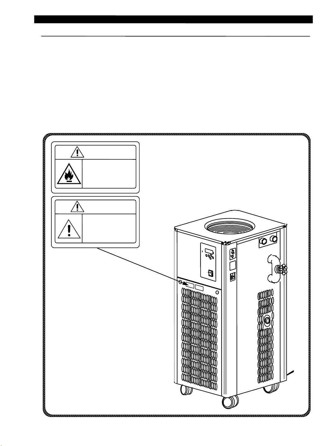
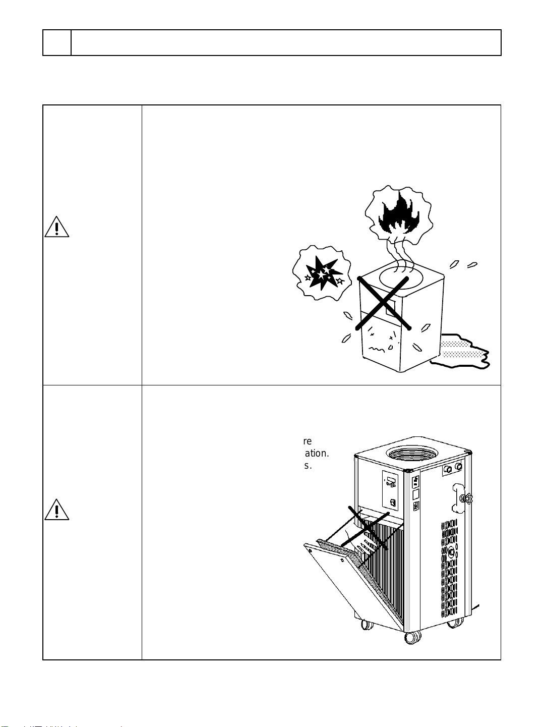
Do not remodel the product.
Make sure that it should not be used
out of intended use.
Remodeling and improper use may cause
electric shock or breakdown.
WARNING This is the cool water circulating machine to
cool down the liquid in the bath with using
cooling machine and circulate the liquid
externally by circulating pump, and to cool
down generating heat part of evaporator,
reaction bath and other devices.
Circulation to open system can be performed
when sealing up cover, which is one of the
options, is used.
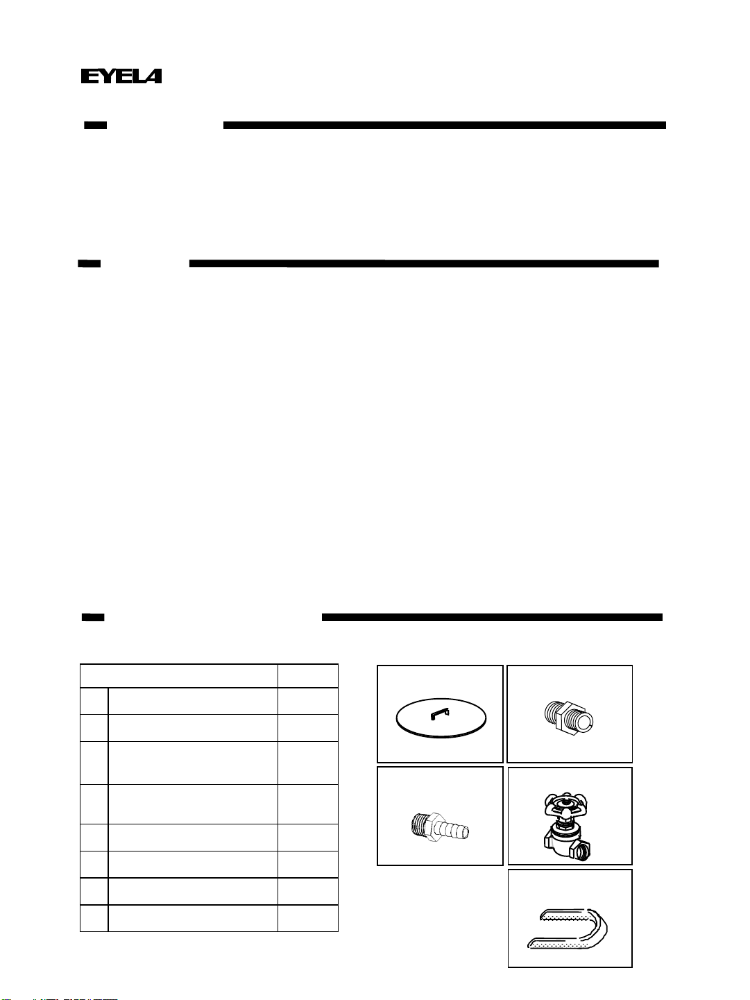
2Outline of the product
Product name Cooling water circulating device (Cool Ace)
Model CA-2610 CA-2610 S
Circulation system Suitable for seal-up circulation
Range of available ambient
temperature 5 to 35⁰C
Range of temperature
control -10 ~35⁰C
Accuracy of temperature
control ±2.0⁰C (Water)
Cooling capacity 3000W at 20⁰C (liquid temperature)
2500W at 10⁰C (liquid temperature)
External
circulation
capacity
Maximum
lifting range 9.5/13m(50/60Hz)
Maximum
flow rate 23.5/27ℓ/min (50/60Hz)
Temperature control
system Caterpillar tube capacity exchanging control + Controlling turning on / off cooling machine
Setting Temp., display Sheet key input・digital display, minimum digit 0.1⁰C
Safety device ad
function
Electric leakage・excess current breaker, self-testing function for temperature controller, Sensor alarm, over load of
cooling machine, high-pressure switch for cooling machine, timer for protecting cooling machine, circulating pump
thermal protector
Included function
Controlling flow amount
function
Alarm out function *5
Output terminal for indictor
External temperature sensor
terminal
Controlling flow amount function
Alarm output function *5
Output terminal for indicator
External temperature sensor terminal
Shutdown switch for emergency case
Remote operation terminal
Optional function Function for detecting pressure abnormality of
circulating water, Function for detecting flow amount decrease of
circulating water
Temperature controller Electronic digital setup・digital display
Temperature sensor Thermistor
Cooling machine・cooling
medium Output: 1100W (Rotary) • R407C
Circulation pump Magnet pump output 41/59W(50/60Hz)
Maximum flow amount: 27/31ℓ/min, Maximum lifting range 9.5/13m(50/60Hz)
Bath Whole capacity Approx. 16.5ℓ Actual capacity Approx. 14ℓ Material SUS304
Cooling coil Copper (Nickel plate)
External circulating nozzle Nozzle, Returning nozzle diameter: Rc1/2
External measurement 450 (W) (bypass valve+10(W)) x 515 (D) x 1010 (H)
Measurement of bath 280 (diameter) x 270 (depth)
Rated supply AC200V single phase 50/60Hz
Power source input 10A 2.0 kVA
Weight Approx. 84 ㎏
*2
*3
*1
*4
-2 -
Features
Functions
Configuration
Spec.

*1 The instrument does not incorporate heater.
Use antifreeze when using the heater at 5⁰C or less.
*2 Conditions
• Room temperature: 20⁰C • Water: 14 L
• Circulation amount: Maximum • Setting: 5 to 35⁰C
• Power source: AC200V 50/60Hz
• Heat load: Cooling capacity: smaller (approx. 90%)/ Cooling capacity: larger (approx. 110%)
• Cooling machine performs ON/OFF operation depending on use conditions (Room temperature,
load, type of secondary refrigerant and the condition of stirring in the bath) and the temperature may be
out of this range, because the cooling machine protection timer works.
• Cooling machine performs ON/OFF operation when preset temperature is from 4 to 10⁰C, and
the temperature may be from ±2 to ±5⁰C depending on use conditions (Room temperature, load, type
of secondary refrigerant and the condition of stirring in the bath), because cooling machine protection
timer works.
*3 Condition
• Room temperature: 20⁰C• Circulation flow: maximum • Power supply voltage: AC 200V 50Hz
• Cooling capacity is ±10%of indicated capacity.
• Cooling capacity varies depending on use condition such as room temperature, load, type of
secondary refrigerant and the condition of stirring in the bath.
*4 Condition
• Water temperature: 20⁰C
• Power supply voltage: AC 200V 50/60Hz
• Circulation capacity id ±10%of indicated capacity.
• Circulation capacity varies depending on the type of secondary refrigerant and etc.
*5 Alarm output is contact output (a-contact).
Contact capacity • AC 250V/DC 30V 3A Max.
-3 -

-4 -
* Circulation capability varies depending on the diameter of discharge nozzle, the
condition of piping, the type of secondary refrigerant and etc.
In case that the circulation is not sufficient, use high pressure pump HPP, which
is one of the options.
* When the circulation pump performs cutout operation, it may cause malfunction of
the pump. For this reason, use bypass valve in order to circulate during operation.
* Cooling capability change starts when the measured temperature
reaches at +4⁰C.
* Cooling capability varies depending on use conditions such as room
temperature, power supply voltage, type of secondary refrigerant, stirring
in the bath and etc.
50Hz
13
Liquid amount (L/min)
025510 15 20
10
5
30
Lifting range (m)
60Hz
2-4 Circulation capability
Condition • AC200V 50/60Hz
• Circulation liquid: Water Liquid temp.: 20⁰C
Refrigerant:Water, Room temperature :20⁰C
Refrigerant:Water, room temperature :35⁰C
Refrigerant:Ethanol, Room temperature :20⁰C
Refrigerant:Ethanol, room temperature :35⁰C
Liquid temperature (⁰C)
-10 010 20 30
0
500
1500
2500
4000
1000
2000
3000
3500
Cooling capacity (W)
2-3 Cooling capability curve (Reference)
Conditions
• AC200V 50Hz
• When bath is stirred. (Circulation amount: Maximum)

2-5 Name of each part
Electric leakage • excess
current breaker
Power cord
Discharge nozzle for
external circulation
(WATER OUT)
Returning nozzle for
external circulation
(WATER IN)
Control panel
Bath cover
Caster
(with stopper)
Shutdown switch for
emergency (2610 S)
Cooling water
circulating bath
Sensor selector switch
External sensor connector
Remote operation selector
(2600 S)
Remote output connector
(2600 S)
Cooling coil
Drain valve (2610 S)
Drain stopcock (2610)
External output connector
Back side
Over head view
Connector for flow
amount switch
Connector for
pressure switch
Screws for attaching flow
amount/pressure switch
(2 screws each)
Strainer
-5 -
Bypass valve
Front
Back

SV
PV
Alarm
⁰C
Refrigerator
Pump
Set Run
Stop
▼
▲
Pump
I
O
Temp.Cont.Valve
3-1 Control panel
3Name and function of operating portion
①Alarm LED
④Cooling machine
operation LED ⑨▲key
⑩▼key
⑥Setting LED
⑦Indicator
⑧Run/Stop Key
⑤Temperature LED
⑪Set key
⑫Pump key
⑬Power switch
②Electromagnetic
valve LED
No. Name Function
①Alarm LED Lights up when outputting alarm.
②Electromagnetic valve LED Lights up when electromagnetic valve for changing capacity is turned on.
③Circulation pump LED Lights up when circulation pump is turned on.
④Cooling machine
operation LED Lights up when cooling machine is turned on.
⑤Temperature LED Lights up when stopping or setting up control. Blinks during control.
⑥Setting LED Lights up when the actual temperature is preset one.
⑦Indicator Displays temperature, setup character and the description of alarm.
⑧Run/Stop Key Starts and stops control.
⑨▲key Available only for setup display. If you press the key, the value increases by
0.1. If you hold down the key, the value will be increased continuously.
Holding down the key longer than 3 seconds can increase the value by 1.0.
In case of control mode, the key changes displaying character.
⑩▼key Available only for setup display .If you press the key, the value decreases by
0.1. If you hold down the key, the value will be decreased continuously.
Holding down the key longer than 3 seconds can decrease the value by 1.0.
In case of control mode, the key changes displaying character.
⑪Set key
Changes over measured value and preset value. Preset value can be re-set
up with “▲key” and “▼key”.
Cancels alarm display when displaying alarm and changes to normal display.
If you hold down the key longer than 5 seconds, the key changes from
normal operation mode to control mode (or from control mode to actual
using mode).
⑫Pump key Turns ON/OFF circulation pump.
⑬Power switch Turns ON/OFF the power.
③Circulation pump
LED
-6 -

3-2 Safety・alarm function
This product is equipped with safety f and alarm
display function as below. In case of trouble, please refer to
"Troubleshooting" on page 32 and follow the
appropriate procedure.
Safety functions
-7 -
Safety device Operation Cause of the trouble
Electric leakage
breaker Turned off and cuts the power
supply. Electric leakage occurs. Or excess current
flows.
High pressure
switch of
cooling
machine
High pressure during the operation
of cooling machine is abnormally
high and the device lights up alarm
lamp and stops the operation of
cooling machine.
• Ambient temperature exceeds 35⁰C.
• Heat load is heavier than cooling capacity
and the temperature rises in the bath.
• Dirt adheres on air filter.
• Fan for cooling machine does not work.
Over load relay
maintaining
circuit of cooling
machine.
Due to over load (over
heat)operation of cooling machine
and etc., the device lights up alarm
lamp and stops operation of cooling
machine.
When it returns to the condition,
driving is automatically resumed.
• Operating ambient temperature exceeds 35⁰C.
• The switching of the power supply frequency
is incorrect.
• Power supply voltage exceeds 200 V ±20
V range.
• The refrigerator fans are not running.
• Not cooled due to too heavy load.
• Dust is attached to the air filter.
• Incorrect use of temperature display
correction
Circulation pump
thermal protector Circulation pump performs over heat
operation and gets stopped. (Will be
recovered automatically
when it is cooled down.)
Over load operation of circulation pump
• Viscosity of circulating liquid is high.
• Sucks foreign substance.
• Ambient temperature exceeds 35⁰C.
• Piping resistance is strong. (Cutout of valve
and etc.)
Temperature
control self-
testing function
Temperature controller does not
work properly and lights up alarm
lamp, and stops all the controls. Will
be recovered automatically after
sorting out the trouble.
• Temperature controller does not work
properly because of noise and etc.
• Ambient temperature exceeds 35⁰C.

Alarm name Alarm display and operation Reasons why alarm works
Maximum temperature
alarm
• Continues to control
• Buzzer beeps for 15 seconds.
• Alarm display
Operation conditions
Alarm works when the temperature in the chamber is
higher than "Preset temp. + maximum preset
temperature for alarm ." temporary. (Maximum preset
temperature for alarm is at 10.0
⁰C at factory default.)
Canceling alarm
• Alarm is canceled when measured temperature
reaches within the range of “Preset temp. + Maximum
preset temperature for alarm“ temporary.
• Alarm can be canceled by [Set] key.
* Maximum preset temperature for alarm can be
changed. (Please refer to "How to operate maximum
preset temperature for alarm" on page 19.)
Minimum temperature
alarm
• Continues to control.
• Buzzer beeps for 15 seconds.
• Alarm display
Operation condition
Alarm works when the temperature in the chamber is
lower than "Preset temp.-minimum preset temperature
for alarm" temporary. (Minimum preset temperature for
alarm is at 5.0
⁰C at factory default.)
Canceling alarm
• Cancels alarm automatically when measured
temperature is within the range of "Preset temp.-
minimum preset temp. for alarm".
• Alarm can be canceled by [Set] key.
* Minimum preset temperature for alarm can be
changed.
(Please refer to "How to operate minimum preset
temperature for alarm" on page 20.)
Blackout alarm
* 2610 S is not output.
• Continues and stops controlling
depending on setting for power recovery.
• Display for continuing control
・制御継続時の表示
• Display for stopping control
Operation condition
Alarm works when blackout occurs during control
(power was cut off without stopping control).
Canceling alarm
Can be canceled by [Set] key.
* Operation after power recovery can be changed.
(Please refer to "How to set up power recovery" on
page 21.)
Alarm function
SV
PV
⁰C
Refrigerator
Pump
Alarm
Temp.Cont.Valve
SV
PV
⁰C
Refrigerator
Pump
Alarm
Temp.Cont.Valve
Displays alternately
SV
PV
⁰C
Refrigerator
Pump
Alarm
Temp.Cont.Valve
SV
PV
⁰C
Refrigerator
Pump
Alarm
Temp.Cont.Valve
Displays alternately
SV
PV
⁰C
Refrigerator
Pump
Alarm
Temp.Cont.Valve
SV
PV
⁰C
Refrigerator
Pump
Alarm
Temp.Cont.Valve
Displays alternately.
-8 -
SV
PV
⁰C
Refrigerator
Pump
Alarm
Temp.Cont.Valve
SV
PV
⁰C
Refrigerator
Pump
Alarm
Temp.Cont.Valve
Displays alternately

Alarm name Alarm display and the description of
operation The reason why alarm works.
Alarm for cooling
machine
• Stops control and circulation pump.
• Buzzer beeps for 15 seconds.
• Alarm display.
Operation condition
High pressure switch for cooling machine works Or the
refrigerator circuit protector operated.
Canceling alarm
• Alarm can be canceled by [Set] key if high
pressure switch is recovered.
Sensor alarm
• Stops control and circulation pump.
• Buzzer beeps for 15 seconds.
• Alarm display
Operation condition
・Internal sensor broken.
• Sensor selector switch is on "OUT" side when
internal sensor controls. Or external sensor connector
is disconnected.
Canceling alarm
•Turn off the power switch once and cancel the
alarm by [Set] key.
Watch dog
• Reset microcomputer and try to restart
the control. Stops control if
microcomputer will not be back in normal
status. • Alarm display (undetermined)
Operation condition
• Temperature controller does not work properly
because of noise and etc.
• Ambient temperature exceeds 35⁰C.
Canceling alarm
• Change environment and power source before
operation.
SV
PV
⁰C
Refrigerator
Pump
Alarm
Temp.Cont.Valve
SV
PV
⁰C
Refrigerator
Pump
Alarm
Temp.Cont.Valve
SV
PV
⁰C
Refrigerator
Pump
Alarm
Temp.Cont.Valve
Alarm name Alarm display and the description of
operation The reason why alarm works.
Alarm for
abnormal
pressure of
circulation water
• Stops control and circulation pump.
* The refrigerator will continue to control.
• Lights up alarm lamp of the main part of
the switch.
• Buzzer beeps for 15 seconds.
•Alarm display
Operation condition
Pressure of circulation water reaches at preset
value of pressure switch.
Canceling alarm
• Turn off the power switch once and cancel the
alarm by [Set] key.
Alarm for
lowering flow
amount of
circulating water
Operation condition
Flow amount of circulation water reaches at
the preset value of flow amount switch.
Canceling alarm
• Turn off power source switch once and cancel
the alarm by [Set] key.
Alarm function (Option)
SV
PV
⁰C
Refrigerator
Pump
Alarm
Temp.Cont.Valve
-9 -

4-1 Setup environment
4Setup
- 10 -
CAUTION
Be careful of setup environment.
Especially, care should be taken on setup
location, air conditioning and ventilation.
Due to the utilization of air-cooling system cooling
machine, heat is exhausted from the unit. Use the
product at the location where is with good
ventilation and conditioning for preventing
ambient temperature from rising high.
If the ambient temperature rises high, the
operation efficiency will be worsened, which will
lower the cooling capacity as well. Also, high
temperature and high pressure operation of
cooling machine may cause breakdown.
60cm
20cm 40cm
4-2 Setup conditions
CAUTION
Making enough space around the unit.
To maintain the function of the project, leave
the space between the product and wall surface
and ceiling plane. Space should be larger than
the one shown on the right picture.
CAUTION
Do not put anything on the top of the
product. CAUTION
Heavy weight product -
Attention needs to be paid to carry.
CA-2610, 2610 S Approx. 84kg * Keep enough piping space on the right side.
Do not block airflow orifice.
●No direct sunlight.
●Range of ambient temperature is from 5 to 35⁰C.
●Good ventilation and air-conditioning or the
location which can be ventilated well.
●No inflammable solid, liquid and gas around the unit.
●No dew condensation
●Fewer humidity and dripping
●Fewer dust
●Even and stable
(Check the weight of the product during operation)
●Please use indoors.

4-3 Setup
- 11 -
1) Cancel the lock of caster's stopper.
To cancel the lock, push up the lever of caster's
stopper.
2) Move it to setup location.
* Moving the unit on uneven or bumpy place may
damage the caster. Please carry it when going
through these places.
3) Lock caster's stopper at setup location.
To lock the stopper, push up the lever of caster's
stopper.
4) Slide attached caster holders (4 pcs) into the
right beside of the body. Stop the rolling and
circling of caster and fix with these holders.
CAUTION
Do not tilt the main unit more than 15°.
Cooling machine is equipped with the main unit.
Do not lay the main unit down nor tilt more than
15°when carrying.
Caster holder
FREE
LOCK
Caster
stopper
Caster
Caster with stopper

- 12 -
(1) Check the voltage, phase and capacity of
power source connecting to the product.
The power supply to connect the product is as
shown on the right.
(2) Mains connector is not attached.
Direct wiring with distribution board or connect to
lock-type outlet as shown on the picture.
In the absence of grounding, consult with an
electrical work vendor and provide grounding
based on the type D grounding work.
Product Model Required power source
Voltage Capacity
CA-2610,2610 S AC 200V
Single phase 15A
Grounding 2P type
plug
(Hooking cap)
Required outlet (Lock type)
Earth pole
Power cord
Cable
Tip treatment Cable cross
section
Connection (Color)
Length (approx.) Thickness
(Outer
diameter)
L N E
CA-2610 3m Approx.
8.5mm
No plug
(Peel off the tip
only) 2.0mm2Black White Green
CA-2610S 10m
Power cord specification
*If the power supply capacity is low during start-up and
operation of the refrigerator, the power supply voltage drops,
leading to start-up failure, overcurrent, etc.
4-4 Utility connection
WARNING
Check the voltage, phase and
capacity of power source.
Wrong connection may cause fire or electric
shock.
WARNING
Connect earth cable properly.
Do not connect earth cable to gas pipe or water
pipe for preventing electric shock.
WARNING
Do not use branching socket and
power strip..
Current excess may burn cable or cause fire.
WARNING
Connect earth cable correctly.
To prevent electric shock accidents, never
connect the ground wire to the gas pipe or water
pipe.

5-1 Preparation for operation
5Operation
- 13 -
WARNING
Use extreme care when using
inflammable or combustible solution.
If inflammable or combustible solution (ethanol and
etc.) is left higher than room temperature (or lower than
room temperature for some solutions) , it may
evaporate, catch fire.
CAUTION
Use circulating liquid that does not affect
the material of circulating route.
Material of circulating route of the unit is made of
copper (coating), stainless, brass, Teflon, vinyl
chloride, POM, silicon rubber, denatured PPO and
ethylene-propylene rubber. Use circulation liquid that
does not affect these materials.
WARNING
Do not shorten the piping diameter or
extend the length of hose.
Do not use the hose joint of which its inner diameter is
less than 9mm when the using hose joint differing from
the attached one. Also, use hose with its minimum
necessary length.
CAUTION
Do not use pure water.
Please use tap water or softened tap water. Do not use
ultrapure water or ion exchange water. It dissolves
carbon dioxide in the air and turns into an acidic
solution, making it easier to corrode metals in the
circulation path. Failure of the cooling coil pinhole and
circulation pump, etc. may cause trouble.
1. Connecting to pipe and hose
(1) Screw hexagon nipple into the side of
discharging cooling water (OUT).
(Hexagon nipple and hose joint are rolled up with
tape.)
(2) Screw flow amount controlling valve into
hexagon nipple.
(3) Connect hose joint to the socket on the
returning cooling water side (IN) and flow amount
controlling valve.
(4) Connect hose (internal diameter: 15mm) both
on the returning cooling water side and
discharging cooling water side. Fix the hose
tightly with hose belt and etc. (Hose and hose belt
are not included in the package)
* Use the hose that is made of the materials,
which have appropriate pressure and heat-
resistant for preventing it from being affected by
solution.
* Operating in low temperature range will form
frost on the piping block and worsen the cooling
capacity depending on the length of the pipe.
Protect the pipe with using the tape and etc. for
the purpose of keeping the proper condition.
1/2
100
Socket Hexagon nipple Flow amount
controlling valve Hose-joint
Discharging cooling
water side (OUT)
Socket
Returning cooling water side (IN)
Hose-joint
Discharging
cooling water
Side (OUT)
Cooling
water
returning
side (IN)

- 14 -
When using this unit as a low temperature bath,
connect bypass hose to the nozzle of discharging
cooling water side and returning cooling water
side.
If you turn on circulation pump switch in this
condition, bath will be stirred and cooling capacity
will not be worsen.
Fix the hose with hose belt tightly.
(Hose and hose belt are not included.)
* Liquid will be flowed out from the returning side
in case that the flow amount controlling valve is
closed without connecting bypass hose.
2. Filling cooling water
(1) Check weather the drain stopcock is off from
drain hose when using model 2610, and check
whether the drain is "OPEN" when using model
2610 S.
(2) Pour water (approx. 14ℓ) into cooling water
circulating bath until whole cooling coil is almost
soaked.
* Use antifreeze liquid when using the bath lower
than +5⁰C. However, do not use 100% of
concentration of ethylene glycol or glycol -group
refrigerant, because the viscosity gets higher in
low temperature area and flow amount gets lesser,
also the safety unit (refer to page 7) of circulating
pump starts working. (Since the freezing
temperature differs depending on concentration,
check the temperature range of the antifreeze
liquid.)
* When using water at the temperature
approx.+5⁰C, it will be frozen on the pipe and
worsen the cooling capacity.
* Do not use the liquid that includes foreign
substance. It may cause breakdown.
(3) Check whether discharging amount controlling
valve is "CLOSE".
(4) Put bath cover on the main unit depending on
use condition.
3. Connecting mains connector
Plug mains connector into the outlet after
checking the power
switch is OFF. When not using the power plug,
connect directly to the main power supply.
Drain stopcock for 2610
Drain valve for 2610S
Drain
stopcock Drain hose
Main unit
side
Open
Close
Water level of cooling water
circulating bath
Using the unit as a low temperature bath
Cooling coil

Turn on electric leakage, excess current and power
switch. Measured temperature of the cooling
circulation bath will be indicated after the initial
display (5 seconds) (Measurement mode).
* Product-specific alphabets and numeric values are
displayed in “ “.
1. Setting up temperature
Preset temperature can be changed even when the
machine gets controlled or stops.
1) Setting up temperature (Setting mode)
Press [Set] key. Indicator changes to display
(blinking) temperature and your desired
temperature can be set.
• “Setting up LED (SV)” lights up.
* Temperature is set as the value you preset last
time. Factory default value is 10.0⁰C.
2) Changing preset temp.
Input your desired temperature with [▲] and
[▼] key.
* Every press of [▲] and [▼]key
increases/decreases by 0.1⁰C. If you hold down the
key, the value will be changed continuously, and if
you hold down the key for longer than 3 seconds,
the value will be changed by 1.0⁰C.
3) Confirming preset temperature
[Press [Set] key. Displayed temperature (blinking) is
confirmed and indicator changes to show measured
temperature display.
• “Setting LED (SV) ” lights off.
* If no key operation is done for more than 1 minute
during setting temperature, the indicator changes to
show measured temperature display. In this case,
please follow the same procedure again from 1) to
reset.
* LED status
Initial display
After showing initial
display for 5 seconds,
measured temp. will be
displayed.
1) Setting up temperature (Setting mode)
Press
「 」, “ “ Lights off
「 」, “ 」Lights up
「 」, “ 」Blinks
5-2 How to operate
2) Changing preset temp.
3) Confirming and deciding
preset temperature
- 15 -
Set Run
Stop
▼
▲
Pump
SV
PV
⁰C
Refrigerator
Pump
Alarm
Temp.Cont.Valve
Set Run
Stop
▼
▲
Pump
SV
PV
⁰C
Refrigerator
Pump
Alarm
Temp.Cont.Valve
Electric leakage・excess
current breaker Power switch
ON ON
Set Run
Stop
▼
▲
Pump
SV
PV
⁰C
Refrigerator
Pump
Alarm
Temp.Cont.Valve
Set Run
Stop
▼
▲
Pump
SV
PV
⁰C
Refrigerator
Pump
Alarm
Temp.Cont.Valve
Press
Set Run
Stop
▼
▲
Pump
SV
PV
⁰C
Refrigerator
Pump
Alarm
Temp.Cont.Valve
Press

2. Starting operation
1) Starting temperature control
Press [Run/Stop] key. Temperature control will be
started.
• “Temperature LED (⁰C)” blinks.
• "Electromagnetic valve LED (Temp.Cont.Valve)
lights up when electromagnetic valve for controlling
temperature is turned on.
• Cooling machine is turned on when the
temperature reaches at preset temperature +0.5⁰C.
"Cooling machine LED (Refrigerator)" lights up when
the cooling machine is ON. The machine is turned
off when measured temperature is approx.-1.5⁰C
lower than preset temperature, and "Cooling
machine LED (Refrigerator)“ lights off.
* Protection timer for cooling machine works for 180
seconds. The cooling machine does not re-start up
for 180 seconds after the machine gets stopped
temporary.
* At the time of starting the cooling machine and
adjusting the temperature, the operation sound
of the solenoid valve for switching the cooling
capacity is "clicked", but it is not abnormal.
2) Operating circulating pump
Press[Pump] key. Circulating pump starts working.
Gradually open the flow control valve when the
pump is activated to begin circulation to the outside.
• “Pump LED (Pump) lights up.
* Circulating pump does not operate simultaneously
with [Run/Stop] key.
3) Open bypass valve so that the bath can be stirred.
Please open the bypass valve enough to stir inside
the tank.
4) Adjustment of flow adjustment valve
Open valve for controlling flow amount little by
inches. It starts circulating externally. Make sure that
there's no leak at the connecting part of the hose.
* If circulating pump operates without closing bypass
valve and valve for controlling flow amount, the
pump may be broken down. Also, in case that the
circulation system may be blocked off, set bypass
valve "OPEN" to perform stirring in the bath and
control the valve for controlling flow amount for
avoiding trouble.
* When supplying water to circulation system, the
water level of cooling water circulating bath is
lowered. In case that the cooling coil is exposed, fill
the cooling water.
* When using water, it may be frozen over cooling
coil depending on preset temperature if stirring was
not performed in the bath properly. I this case, set
more amount for circulation of bypass valve. Use
antifreeze if freezing amount is huge.
1) Starting temperature control.
2) Operating circulating pump
Press
Once the cooling machine stops, it will not operate
for about 180 seconds from stop even if the
measured temperature is higher than the set
temperature by about 0.5 ºC.
Cooling machine protection timer function
- 16 -
Set Run
Stop
▼
▲
Pump
SV
PV
⁰C
Refrigerator
Pump
Alarm
Temp.Cont.Valve
Press
Set Run
Stop
▼
▲
Pump
SV
PV
⁰C
Refrigerator
Pump
Alarm
Temp.Cont.Valve
Flow adjustment valve
Open
3) Adjustment of flow adjustment valve
Open
Bypass valve
Circulating hose
This manual suits for next models
1
Table of contents
Other EYELA Fan manuals
Popular Fan manuals by other brands

Nuaire Group
Nuaire Group AXUS Series Installation and Maintenance

Lasko
Lasko 4820 Instructions and operating manual

Chore-Time
Chore-Time Hyflo Assembly manual

ProKlima
ProKlima FN-110192.1 instruction manual

Minka Group
Minka Group F516L-WH Instruction manual warranty certificate

Koncar
Koncar VARSK ABC Series manual