3
1. MODE N°1 : Charge from the original 10mm2 line / Smart Connect 50A
mode (SC)
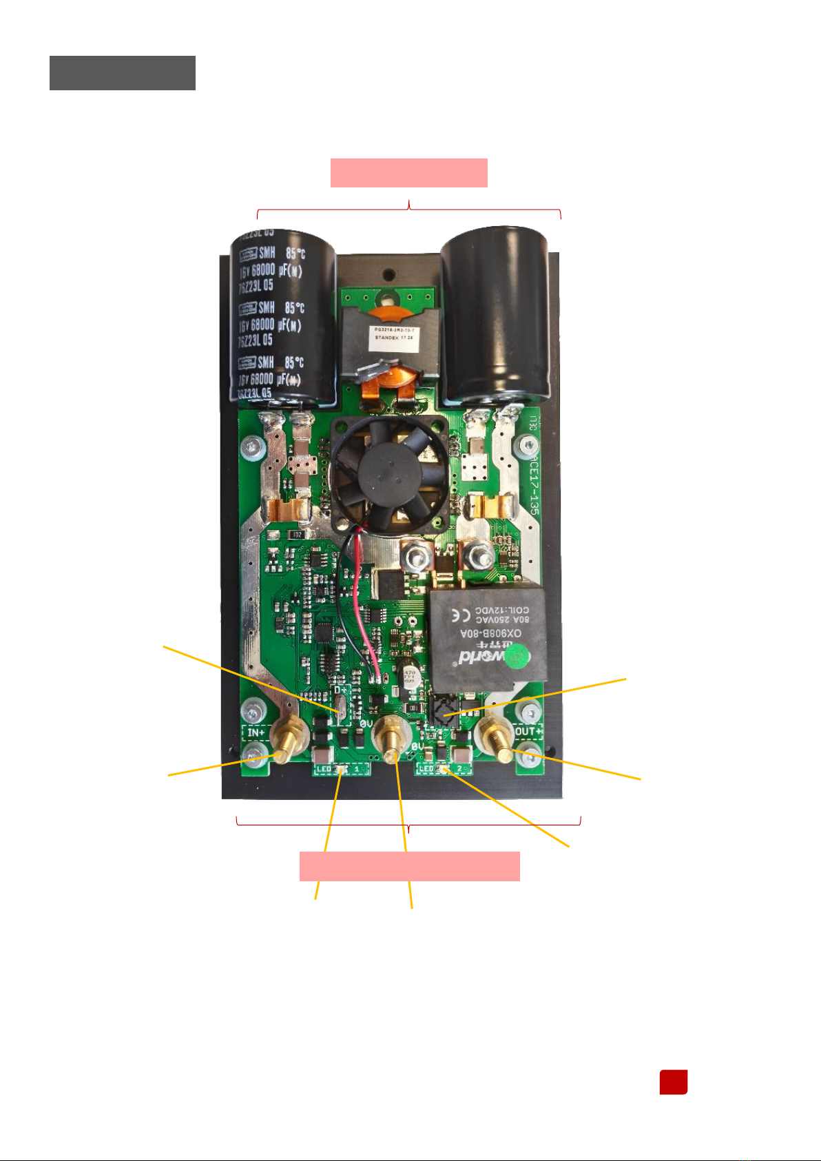
a. Connect the positive of the original line, coming from the EBL, to the IN+ terminal of the module.
b. Connect the positive of the auxiliary Lithium Battery (ENERGIE100) to the OUT+ terminal of the module.
c. Connect the negative of both, original line & lithium battery to the negative terminal of the MBB.
d. Prepare de “D+”line from the vehicle (6.35 blue faston lug) = « engine started » information. Connect the
« D+ » wire to the « D+ » terminal of the module
e. Check if the MBB setting is in the desired mode. Press the selection button on the module to check or to
change the setting.
f. To change the charging mode, if necessary, disconnect the D + from the module and follow the
instructions in nest paragraph.
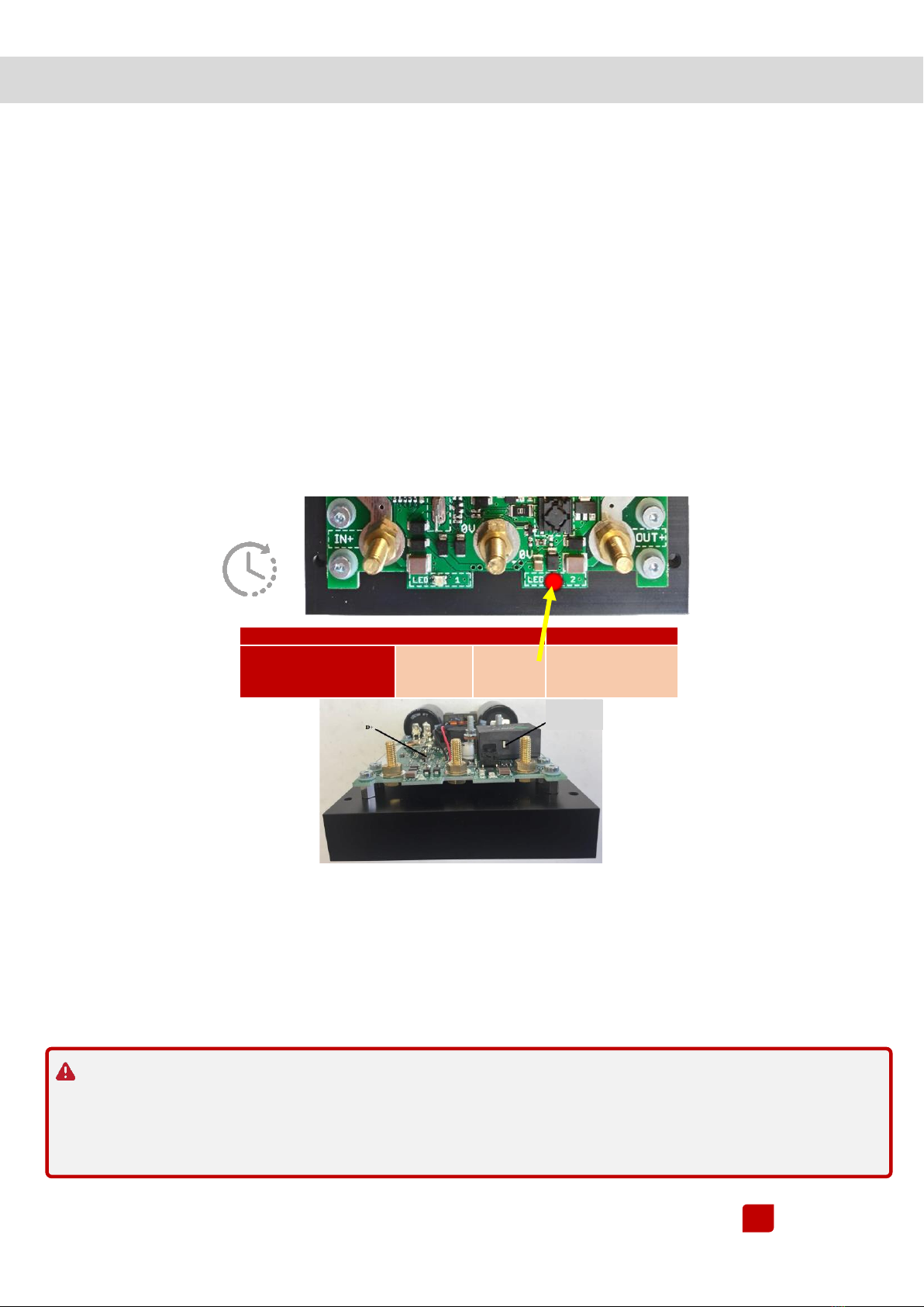
g. Press on the “SELECTION” button of the module (see picture).
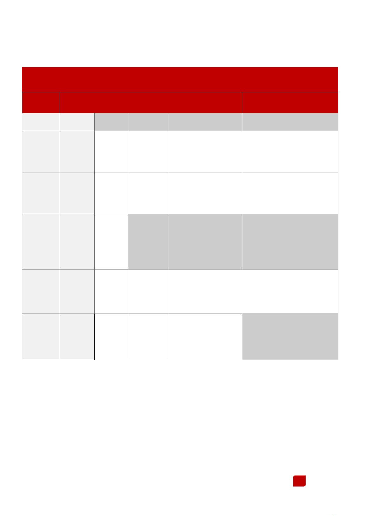
h. Release the SELECTION button : The state of LEDs "LED1" and "LED2" and the position of the switching relay
indicate the set mode according to the following table:
Each new pressure (2-3 seconds) on the SELECTION button will allow to change the charging mode
corresponding to the realized installation.
i. Reconnect the D+, if it was disconnected following instructions of paragraph h.
j. Start the engine to check the engine load and the engine battery coupling powering the cell of the
motorhome when the engine is running,
« BYPASS » SYSTEM
The MBB module MBB works in 2 Ways :
In « Smart Connect » mode (on the original line of the vehicle)
-If présence of D+ (engine on) = DC/DC charge from +IN to +OUT / 50A
-If cutoff of D+ (engine off) = bypass allowing the cell to be powered by the Lithium / 0-60A battery.
In dedicated line mode, the bypass is never activated. All consumers are connected directly to the battery.