eZi eZi-DA66 Operating manual

eZi-DA66 Installation Manual Revision 1.2 Page 1
Professional Multi-Room / 6 Source 6 Zone Audio S stem
User and Installation Manual
Home Audio Distribution System
eZi-DA66
eZi
-
DA66

eZi-DA66 Installation Manual Revision 1.2 Page 2
TABLE OF CONTENTS
SAFETY INSTRUCTIONS ........................................................................................................................................................................................................................................ 3
INTRODUCTION .................................................................................................................................................................................................................................................... 4
PACKAGE CONTENTS ............................................................................................................................................................................................................................................ 4
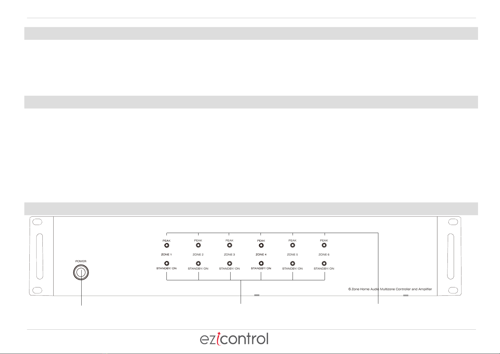
AMPLIFIER FRONT PANEL .................................................................................................................................................................................................................................... 4
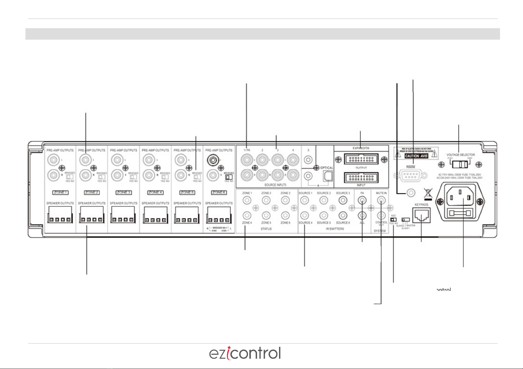
AMPLIFIER REAR PANEL ....................................................................................................................................................................................................................................... 5
KEYPADS ............................................................................................................................................................................................................................................................... 6
INFRARED REMOTE CONTROL ............................................................................................................................................................................................................................. 7
INSTALLATION INSTRUCTIONS - IMPORTANT ..................................................................................................................................................................................................... 8
SETTING THE KEYPAD MODE DIP SWITCHES ....................................................................................................................................................................................................... 8
KEYPAD WIRING ................................................................................................................................................................................................................................................... 9
KEYPAD CABLE INFORMATION .......................................................................................................................................................................................................................... 10
INSTALLATION OF KEYPAD HUB - EARTH .......................................................................................................................................................................................................... 10
INSTALLATION OF KEYPAD HUB – CAT5 ............................................................................................................................................................................................................ 10
SPEAKER INSTALLATION – IMPORTANT ............................................................................................................................................................................................................ 11
SPEAKER INSTALLATION – STEREO MODE SPEAKER INSTALLATION - BRIDGE MODE ............................................................................................................................ 11
SPEAKER INSTALLATION – PRE AMP OUT SPEAKER INSTALLATION – 100V LINE ..................................................................................................................................... 12
CONNECTING SOURCES ...................................................................................................................................................................................................................................... 13
INFRARED EMITTER OUTPUTS ........................................................................................................................................................................................................................... 13
12VDC TRIGGER OUTPUTS ................................................................................................................................................................................................................................. 14
12VDC TRIGGER INPUTS .................................................................................................................................................................................................................................... 15
MASTER SLAVE ................................................................................................................................................................................................................................................... 15
RS232 PORT ........................................................................................................................................................................................................................................................ 16
HD Ma rix RS232 PORT – Only available on eZi-DA66-HD models .................................................................................................................................................................. 16
SPECIFICATIONS ................................................................................................................................................................................................................................................. 16

eZi-DA66 Installation Manual Revision 1.2 Page 3
SAFETY INSTRUCTIONS
SAFETY WARNINGS AND INSTRUCTIONS
To avoid personal injur or damage to the equipment, please adhere to the following safet guidelines:
1. Do not expose this device to water or moisture of an kind. Do not place objects filled with liquids on or near this device.
2. Do not install this device in an enclosed space. Ensure that there is sufficient ventilation to keep the unit from overheating.
3. Do not place objects on this device or otherwise block the cooling vents.
4. Do not install near an heat sources, such as stoves, radiators, or fireplaces.
5. Do not place naked flames, such as candles, on or near this device.
6. Clean onl with a dr cloth. Do not use liquid cleaners or solvents to clean this device.
7. Unplug the unit during lightning storms or when the unit will be unused for a long period of time.
8. Do not allow the power cords to be walked on, pinched, tripped over, or otherwise damaged.
9. Do not attempt to defeat the grounded AC power plug b using a "cheater" plug adapter or modif ing the power cable. If the grounded
plug will not fit in our AC power outlet, please contact a professional electrician to replace the obsolete outlet.
10. Ensure that an cables that are run through the walls or between floors are properl rated for "in-wall" or "riser" use. Use of unrated
cables could contribute to the rapid spread of an fire and could invalidate insurance claims.
RISK OF ELECTRIC SHOCK
DO NOT OPEN
WARNING! TO REDUCE THE RISK OF FIRE OR
ELECTRIC SHOCK, DO NOT EXPOSE THIS
APPLIANCE TO RAIN OR MOISTURE.
CAUTION! TO REDUCE THE RISK OF SHOCK, DO
NOT REMOVE THE COVER, NO USER SERVICABLE
PARTS INSIDE. REFER SERVICE TO A QUALIFIED
SERVICE TECHNICIAN.

eZi-DA66 Installation Manual Revision 1.2 Page 4
INTRODUCTION
This manual is for EZI-DA66 and eZI-DA66-HD. Thank ou for purchasing the EZI-DA66 Home Audio Distribution S stem. The EZI-DA66 is a full
function distributed audio s stem, which combines the functions of a preamplifier, a full 6x6 audio matrix, and six 50-watt power amplifiers for
driving speakers in up to six separate zones. EZI-DA66-HD has a serial port to send commands to an HD matrix to allow HDTV source selection in each zone to follow
the selected zone source Additionall , up to three units can be combined to provide full signal switching and amplification to up to 18 different
speaker zones. For best results, please read and understand this manual thoroughl before installation, pa ing particular attention to the
safet warnings and guidelines. Keep this manual in a safe place for future reference.
PACKAGE CONTENTS
After receiving the product please inventor the contents to ensure ou have all the parts listed below. If an thing is missing or
damaged, please contact Customer Service for a replacement.
1x EZI-DA66 master controller/amplifier
6x Ke pad controllers
1x Ke pad hub
1x Infrared remote control
1x Expansion ribbon cable
1x Rack mounting kit
1x AC power cord with South African 3 Pin plug
1x User's manual
AMPLIFIER FRONT PANEL
Power On/Off/ Standby
Press to power the unit ON. Press again to
power the unit OFF. Note when Master
Controller is ON, each zone will remain in
Standby until the zone keypad is activated.
Zone ON/STANDBY LED
LEDs illuminate to indicate the status of each
zone. The LED will glow Blue when in Standby
and will glow White when activated.
Zone PEAK LED
LEDs illuminate to indicate input level of the connected source is
too high. Normal for LED to flash red occasionally. Steady or red
most of the time indicates input level should be reduced.

eZi-DA66 Installation Manual Revision 1.2 Page 5
AMPLIFIER REAR PANEL
Stereo line level pre-amp outputs for ever
zone. Connect powered sub-woofers or high
power zone amplifiers or commercial audio
amplifiers
.
6 x 50 watt stereo amplifiers
or 6 x100 watts in bridge mono
mode amplifiers.
Paging capabilit for Input
1 to broadcast to all zones
when 12Vdc is applied to
the PA - IN jack
Six stereo analog inputs
Expandable to 18 zones
with 3 x Multizone
Controller s stems.
RS232 Control – eZi-UHAP
or MZC emulation.
Dual Voltage Selector.
MUST BE 230V
12 high qualit amplifiers with 50 watts output
power @ 4ohms or 100 watts @ 8ohms in
bridge mono mode with removable terminal
block connectors
.
Zone activated 12Vdc
triggers x 6 IR Outputs 6 routed
& 1 common
12Vdc input paging
trigger
Mute the entire s stem with
the 12Vdc MUTE IN.
Use the 12Vdc CONTROL
OUTPUT to trigger source
equipment or home theatre
equipment
Auto gain control
(AGC)protects against
amp overload.
To Ke pad Hub for
6 ke pads.
AC 230V 50Hz
mains power
HD Matrix Serial Port
Onl on eZi-DA66-HD
models.

eZi-DA66 Installation Manual Revision 1.2 Page 6
KEYPADS
The Multizone Controller ke pads are available in white and are designed to be ver eas to use. Five backlit buttons access zone power on/off, volume
up/down, selection of sources 1-6, zone treble, zone bass, zone unmute and zone standb . The backlit LED displa provides visual feedback of levels and
source numbers. The Multizone Controller ke pad also provides an Infrared receiver which allows complete zone control via the included Multizone
Controller-RC hand held remote control. The Multizone Controller IR s stem also sends IR commands to the Multizone Controller master controller IR
output jacks for remote control of our source components. No programming necessar , just touch the ke pad and start pla ing music instantl !
NUMERIC LED DISPLAY
Ext/Mute/PA selection LED
Volume up/down LED
Source selection
LED
Infrared (IR) receiver
Down, volume, treble, bass, un
-
mute
Source 1
-
6 descending
Source 1
-
6 as
cending
Treble up/down LED
Bass
up/down LED
Up, volume, treble, bass,
Power on/off & mode select button
Hold for 3 seconds for zone on/off Press
repeatedl for volume, source, treble
and bass adjustment mode. Use the
select button with the volume up/down
buttons to adjust volume levels, treble
and bass levels.
Night Light, the select button emits a
soft glow at night when the zone is
powered off.

eZi-DA66 Installation Manual Revision 1.2 Page 7
INFRARED REMOTE CONTROL
Infrared (IR) emitter.
Zone power on/off.
Bass up/down.
Balance right.
Zone mute
Source selection 1-6
Treble up/down
Volume up/down
Balance left

eZi-DA66 Installation Manual Revision 1.2 Page 8
INSTALLATION INSTRUCTIONS - IMPORTANT
The Multizone Controller should be situated in a well-ventilated position. Never block the vents on the sides or top of the chassis. Proper ventilation is
essential. Do not expose the unit to excessive dust. Do not allow dust to build and block vent holes. Do not place the Multizone Controller above or below
heat-generating components such as audio amplifiers. Allow at least 50mm (1U) of space to the sides of the chassis with open air flow above and below.
Before making an connections ensure that eZi-DA66 is powered off and unplugged to prevent personal injur or equipment damage due to electrical
shock.
1. The Multizone Controller can be mounted in an equipment rack using the rack kit that is included.
2. Alwa s disconnect the AC power cord before making an connections to the Multizone Controller. Ensure the Voltage selector above the mains
socket is set on the correct voltage (220V) for South Africa.
3. Use good qualit 2mm
2
to 3mm
2
(12 to 14awg) conductor stranded copper speaker wire for all speaker connections.
4. Use good qualit cat5e or cat6 cable and RJ45 connectors for all Multizone Controller ke pads.
5. The Multizone Controller includes a central ke pad hub. All Multizone Controller ke pads will be home run back the hub. Keep the hub close the
Multizone Controller.
6. Wire all cat5e/cat6 cables exactl the same using TIA/EIA 568A wiring. Do not use crossover cables.
7. Controller ke pads must have their mode dip switches set properl before powering the s stem on.
8. Onl 1 ke pad is allowed per zone.
9. Set the three DIP switches on each ke pad to one of the six addresses listed below. Each Ke pad connected to the same Master
Controller/Amplifier must have a unique address.
10. The address is localized to each Master Controller/Amplifier device. If multiple Controllers are in use, each one will have its own set of ke pads with
the same address numbers as ke pads on the Master Controller.
11. The DIP switches work with ON=logic0 and OFF-Logic1. Zone1 = 001 = (1)ON (2)ON (3)OFF – see detailed explanation and diagram below:
SETTING THE KEYPAD MODE DIP SWITCHES
Each ke pad has a hand mode selection chart on the back as follows: Switch in the UP position is ON or LOGIC 0. Switch in the down position is OFF or
LOGIC1. Switch 1 is the Binar MSB or Most Significant Bit. Use binar value to set the Zone.
ZONE
SWITCH1
SWITCH2
SWITCH3
1 ON ON OFF
2 ON OFF ON
3 ON OFF OFF
4 OFF ON ON
5 OFF ON OFF
6 OFF OFF ON
ON
1 2 3

eZi-DA66 Installation Manual Revision 1.2 Page 9
KEYPAD WIRING
IMPORTANT: Use a screwdriver to install the ke pad.
Using a power drill can damage the ke pad.
The Multizone Controller ke pad should be mounted in an electrical back box using a screwdriver to tighten. Do not use a power drill to tighten the ke pad
screws. Over tightening can damage the ke pad.
Use a good qualit Cat5e/6 cable and crimp RJ45 jacks on each end of the cables. The RJ45 jack plugs into the back panel of the ke pads and the 6 x RJ45
jacks on the ke pad hub. The Multizone Controller ke pad hub is included in our Multizone Controller kit. Plug the RJ45 jacks into an available jack on
the Multizone Controller ke pad hub. Zone assignment is determined b the MODE dip switches on the back of the Multizone Controller ke pad.
Zone Ke pad
CAT5e/6 +/- 200m per run
CAT5e/6 Ke pad Hub +/-5m
Ke pad Hub

eZi-DA66 Installation Manual Revision 1.2 Page 10
KEYPAD CABLE INFORMATION
Long runs of CAT cable running to various parts of a house makes the s stem susceptible to EMI (Electro Magnetic Interference). The CAT
cables running from the DA-66 to each ke pad operate as antennae’s which in the presence of high EMI such as during a lightning storm
can lead to voltage spikes being introduced into the CAT cable. To mitigate this risk, a Ke pad HUB with surge protection is supplied with
each eZi-DA-66.
INSTALLATION OF KEYPAD HUB - EARTH
The Ke pad Hub is supplied with a lug on a 300mm fl lead. Connect the lug to an screw on the Ke pad Hub and the other end of the fl
lead to an earth point. Please ensure that the earth connection is tested to the earth of the installation – without a reliable earth
connection, the energ generated during a surge will not have a dissipation path resulting in damage to the eZi-DA66 and/or ke pads
INSTALLATION OF KEYPAD HUB – CAT5
The Ke pad Hub has 7 x RJ45 connectors each with heav dut surge protection circuitr connected to a common bus. Connect the ke pads
to the 6 x RJ45 connectors next to each other in order of Zone 1 to 6 from left to right. This is onl for ease of maintenance as the RJ45’s
are not zone dependant (common bus). Connect the RJ45 that is separate from the 6 x RJ45’s to the RK45 Ke pad of the eZi-DA66.
REMEMBER to power the unit off when connecting or changing the Ke pad Zone DIP switches

eZi-DA66 Installation Manual Revision 1.2 Page 11
SPEAKER INSTALLATION – IMPORTANT
IMPORTANT: The Multizone Controller amplifiers are capable of driving 4 Ω to 8 Ω speaker loads in stereo mode and 8 Ω loads in bridge mono mode.
Never connect more than two 8 Ω speakers wired in parallel to a single amplifier channel in stereo mode. Never connect more than one 8 Ω speaker to a
single channel in bridge mono mode. Never connect the Left & Right channels of the amplifier together. Never combine the – negative channels of the
amplifier together. Improper speaker installation can damage the amplifiers and void the warrant . If ou are unsure how to connect speakers to the
Multizone Controller alwa s contact a qualified technician or contact iLED before connecting speakers to the amplifiers.
SPEAKER INSTALLATION – STEREO MODE SPEAKER INSTALLATION - BRIDGE MODE
Use good qualit 2mm
2
to 3mm
2
(12 to 14awg) stranded copper speaker
wire that shows the – and +. Never run speaker wires parallel to AC wires. If
ou must cross AC wires alwa s cross at a 90-degree angle. The speaker
output terminal block connectors are removable. Remove the terminal
block connector and make sure that all connections are open b turning
each set screw counter clockwise. This insures that the speaker wire opening
is completel open. Trim approx. 6mm of insulation from the speaker wire
and twist the copper ends. Insert the speaker wires into the connector and
tighten the set screws. Alwa s connect Amplifier + to Speaker + and
Amplifier - to Speaker. Make sure the Bridged switch is set to NO. Repeat for
the remaining zones
Use good qualit 2mm
2
to 3mm
2
(12 to 14awg) stranded copper speaker
wire that shows the – and +. Never run speaker wires parallel to AC wires.
If ou must cross AC wires alwa s cross at a 90-degree angle. The speaker
output terminal block connectors are removable. Remove the terminal
block connector and make sure that all connections are open b turning
each set screw counter clockwise. This insures that the speaker wire
opening is completel open. Trim approx.. 6mm of insulation from the
speaker wire and twist the copper ends. Insert the speaker wires into the
connector and tighten the set screws. Connect Amplifier + to Speaker + and
Amplifier - to Speaker – using the terminals shown. Make sure the Bridged
switch is set to YES. Repeat for the remaining zones

eZi-DA66 Installation Manual Revision 1.2 Page 12
SPEAKER INSTALLATION – PRE AMP OUT SPEAKER INSTALLATION – 100V LINE
example powered sub woofer example 100v line
The eZi-DA66 Controller provides 6 x stereo unbalanced line
level PRE-AMP outputs which correspond to the 6 x zone
outputs. PRE-AMP outputs can be used to connect powered
subwoofers to a zone or additional amplifiers to expand the
available power in a large zone or multiple zones.
The eZi-DA66 Controller provides 6 x stereo unbalanced line level PRE-AMP
outputs which correspond to the 6 x zone outputs. PRE-AMP outputs can be
used to connect powered subwoofers to a zone or additional amplifiers to
expand the available power in a large zone or multiple zones
.

eZi-DA66 Installation Manual Revision 1.2 Page 13
CONNECTING SOURCES
The Multizone Controller provides 6 x stereo unbalanced line level source inputs which can be accessed b an zone. Input 1 can be used as a paging (all
zones) input or a part mode (all zones) input. When a source is connected to input 1 and 12VDC is applied to the PA-IN jack (3.5mm tip+ sleeve -), source 1
will be broadcast in all zones. If there is no DC voltage applied to the PA-IN jack then source 1 will act like all the other 5 sources and broadcast onl when a
zone selects source 1. Alwa s use good qualit shielded RCA cables to connect sources to the Multizone Controller and keep RCA cables as short as possible
to avoid RF interference.
INFRARED EMITTER OUTPUTS
This s stem has the abilit to repeat IR signals from each speaker zone to control the source devices. The IR signal from the Master Controller to the
source device requires IR emitters (not included) connected to the Master Controller via a 3.5mm TS plug. The IR repeater function supports single-band IR
signals in the 38KHz range onl . To install an IR emitter, insert the 3.5mm plug for the emitter into the appropriate IR emitter jack. Position the emitter
bulb so that it is within range and has a clear line-of-sight to the source device(s). If the emitter cord is not long enough, ou can use an 3.5mm TS or TRS
extension cable to extend its reach.

eZi-DA66 Installation Manual Revision 1.2 Page 14
12VDC TRIGGER OUTPUTS
6 x 12VDC trigger outputs which correspond to the 6 x Multizone Controller zones are provided. When a zone is powered ON b pressing and holding the
SELECT button on the Multizone Controller ke pad for 3 seconds the corresponding zone sends 12VDC to the trigger output jack. When the zone is
powered OFF the routed 12VDC signal is disengaged. Triggers can be used to automaticall power peripheral equipment ON/OFF with the Multizone
Controller zones. The Multizone Controller also provides a master control 12VDC trigger output which sends 12VDC to the CONTROL OUT jack when an
zone is powered ON. The 12VDC CONTROL OUT signal is disengaged when all zones are powered OFF.
3.5mm mono plug polarit TIP + / SLEEVE -

eZi-DA66 Installation Manual Revision 1.2 Page 15
12VDC TRIGGER INPUTS
•PA- IN. Insert 12VDC and Input 1 takes priorit over all other inputs and broadcasts to all 6 zones.
•MUTE – IN. Insert 12VDC and all zones will be muted.
MASTER SLAVE
To use
multiple eZi-DA66’s, connect them together using the ribbon cable supplied with each unit. Ensure that all the eZi-DA66’s are powered off and the
mains socket removed BEFORE connecting the ribbon cables
3.5mm mono plug polarit TIP + / SLEEVE -
1. Decide which device will be the Master
device. Slide the Master/Slave switch on
this unit to the Master position.
2. Plug one end of the included ribbon cable
into the Expansion Output port on the
back of the Master device. Plug the other
end into the Expansion Input port on the
back of the first slave device.
3. Slide the Master/Slave switch on the first
slave device to the Slave 1 position.
4. If connecting a third device, plug one end
of the included ribbon cable into the
Expansion Output port on the back of the
first slave device. Plug the other end into
the Expansion Input port on the back of
the second slave device.
5. Slide the Master/Slave switch on the
second slave device to the Slave 2
position.
Mas er/Slave
selec

eZi-DA66 Installation Manual Revision 1.2 Page 16
RS232 PORT
DB9 Female RS-232 serial port connection located on the back panel of the Multizone Controller provides 2 wa serial communications. Refer to eZi-DA66
RS232 serial protocol document for detailed instructions. The RS232 port pins are shown below with a few examples of cables.
HD MATRIX RS232 PORT – ONLY AVAILABLE ON EZI-DA66-HD MODELS
DA-66-HD models have a s ereo mini jack serial por moun ed below the DB9 main serial port. This provides control of external HD video matrix
switchers. Each time a source is changed in a zone from the ke pad or external RS232 command, the serial command for the selected matrix switcher will
be transmitted on this port allowing the HD video to follow . Refer to eZi-DA66-HD RS232 serial protocol document for detailed instructions.
SPECIFICATIONS
RMS Power @ 8Ohms 25 watts x 12 Trigger S stems ON Voltage +12v DC
RMS Power @ 4Ohms 50 watts x 12 Trigger External Mute Voltage +12v DC
RMS Power @ 8 Ohms Bridged 100 watts x 6 Infrared Frequenc 38kHz
S/N Ratio >85dB A Weighted Input Connectors 3.5mm Stereo, RCA, SPDIF
THD <0.1% Output Connectors Terminal Block 3.5mm mono
Frequenc Response 20Hz-20kHz Power Suppl Set to 230V/50Hz
Input Impedance >47K Ohms Dimensions in mm 430W x 89H x 416D
Input Sensitivit 250mV Weight 11kg
Amplifier Protection Overload/Short Circuit/Thermal Warrant 1 ear from invoice
eZi-DA66 RS232 DB9 Female Cable from eZi-DA66 to BC2/BC4 Phoenix Cable from eZi-DA66 to BC1/BC2 DB9
Pin Function DB9 Male Phoenix block DB9 Male DB9Female
2
Rx - Data in 2
-------------- 3 2
-------------- 3
3
Tx - Data Out 3
-------------- 2 3
-------------- 2
5
Signal Ground 5
-------------- 1 5
-------------- 5
iLED Part Number RS232-DB9-F iLED Part Number RS232-Crossover
eZi-DA66-HD RS232 Mini Jack Stereo Female
Pin Function
TIP
Tx - Data Out
R1
Rx - Data In
R2
Signal Ground
TIP – TX – Da a Ou
RING1
–
RX
–
Da a In
RING2 – Signal
Table of contents
Popular Amplifier manuals by other brands

PowerAcoustik
PowerAcoustik PWR 260 instruction manual

T L Audio
T L Audio ITUBE CARBON EDITION user manual

Audiosystem
Audiosystem HX 360.2 owner's manual

VOX Amplification
VOX Amplification VOX Adio Air BS owner's manual

MEDIA TECHNOLOGY SYSTEMS
MEDIA TECHNOLOGY SYSTEMS DS Series manual

Mark Bass
Mark Bass LITTLE MARK NINJA COMBO Series owner's manual