2
S20
meccanica
FADINI
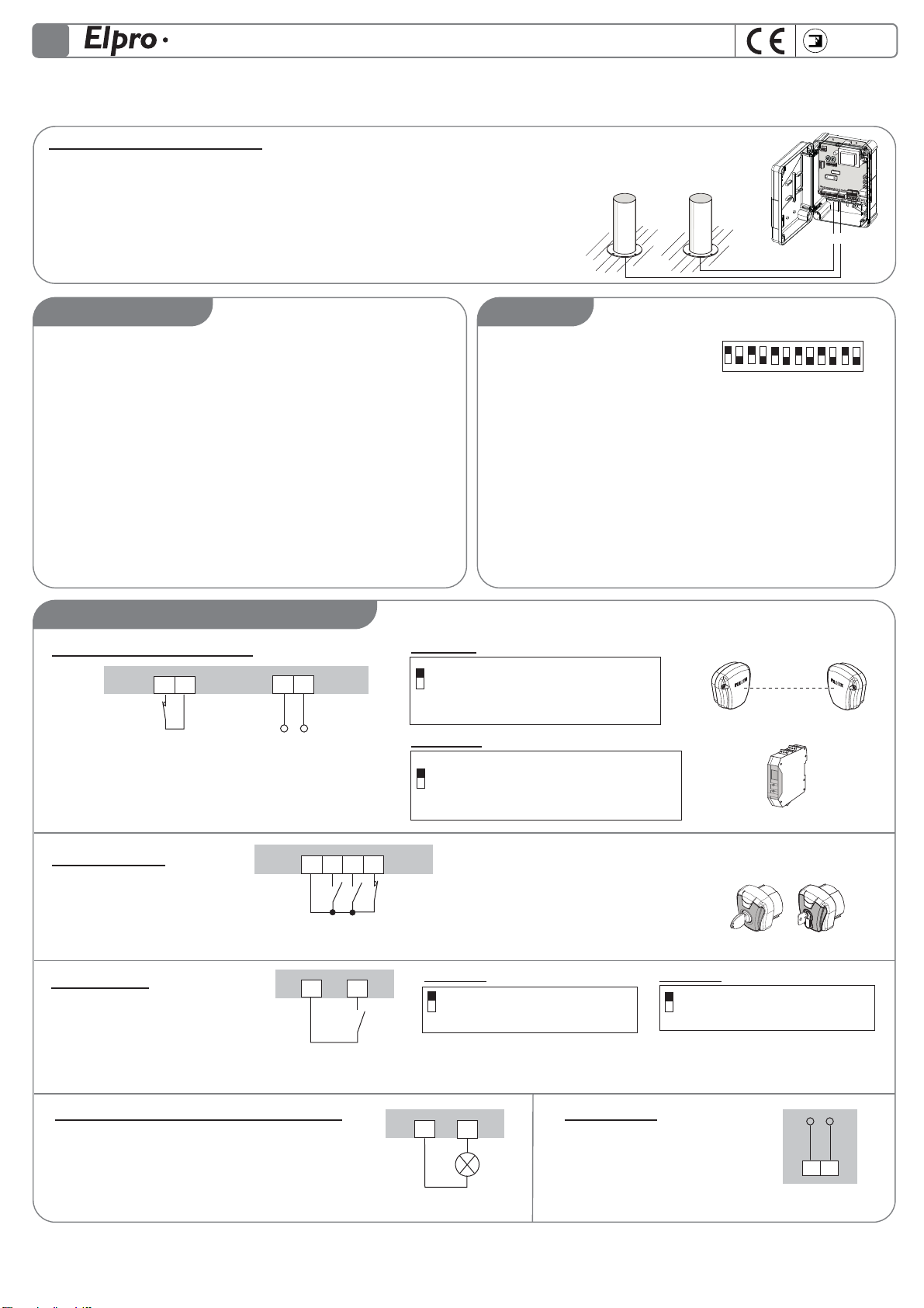
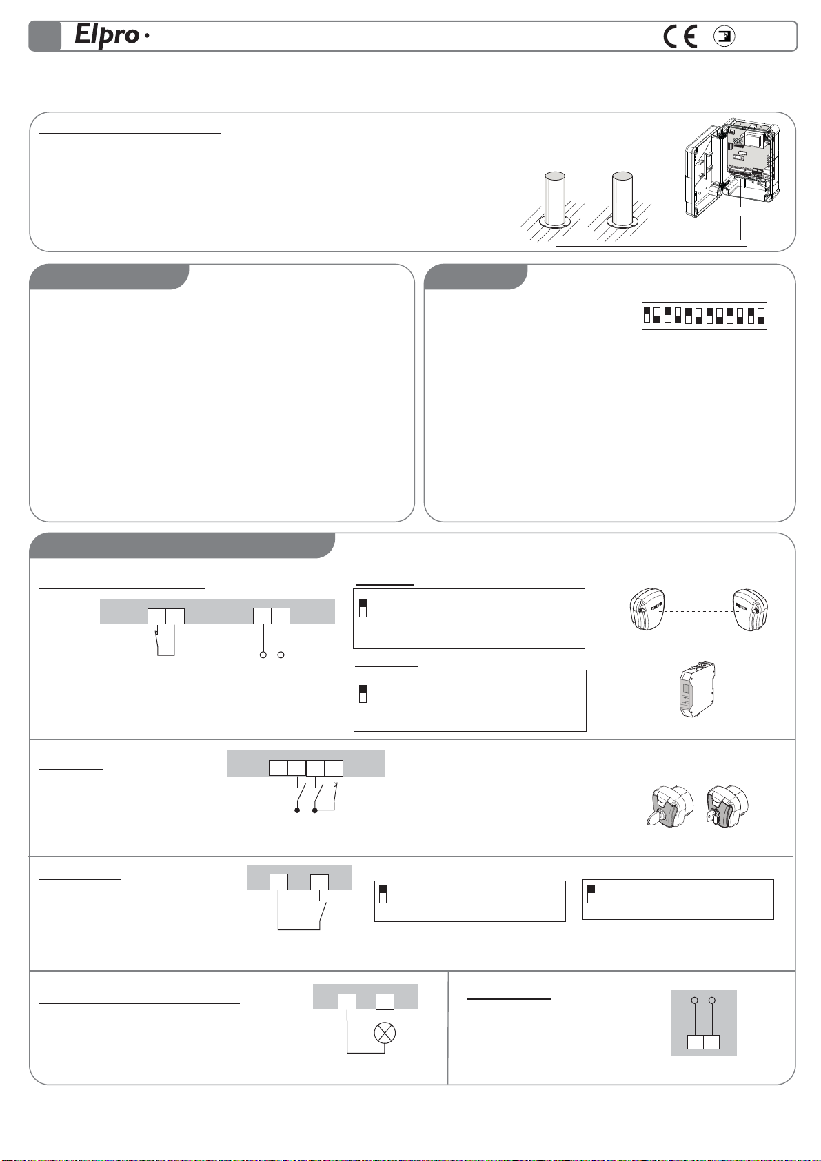
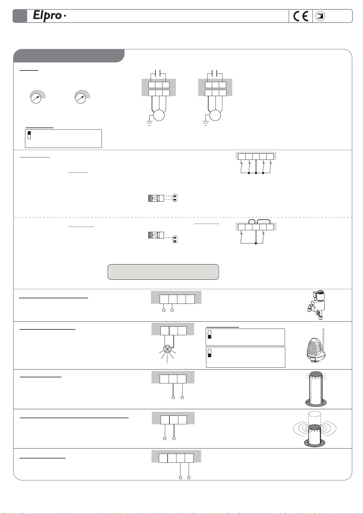
PROGRAMMATORE FINO A 2 DISSUASORI A SCOMPARSA CON O SENZA FINECORSA
I
AVVERTENZE GENERALI PER LA SICUREZZA DELLE PERSONE
INTRODUZIONE
Questa automazione è stata progettata per un utilizzo
esclusivo per quanto indicato in questo libretto, con gli
accessori di sicurezza e di segnalazione minimi richiesti e con i
dispositivi FADINI. □Qualsiasi altra applicazione non
espressamente indicata in questo libretto potrebbe provocare
disservizi o danni a cose e persone. □Meccanica Fadini snc non
è responsabile per eventuali danni derivati da usi impropri e
non specicatamente indicati in questo libretto; non risponde
inoltre di malfunzionamenti derivati dall'uso di materiali e/o
accessori non indicati dalla ditta stessa. □La ditta costruttrice si
riserva di apportare modiche ai propri prodotti senza
preavviso. □Tutto quanto non espressamente indicato in
questo manuale di istruzioni non è permesso.
PRIMA DELL'INSTALLAZIONE
Prima di qualsiasi intervento valutare l'idoneità dell'ingresso da
automatizzare, nonché la sua condizione e la struttura. □
Accertarsi che non si verichino situazioni di impatto,
schiacciamento, cesoiamento, convogliamento, taglio,
uncinamento e sollevamento, tali da poter pregiudicare la
sicurezza delle persone. □Non installare il prodotto nelle
vicinanze di fonti di calore ed evitare il contatto con sostanze
inammabili. □Tenere lontano dalla portata di bambini
qualsiasi dispositivo (trasmettitori, lettori di prossimità,
selettori, ecc.) atto ad avviare l'automazione. □Il transito nella
zona di luce di passaggio deve avvenire unicamente con
l'automazione ferma. □Non consentire a bambini e/o persone
di stazionare nei pressi dell'impianto con l'automazione in
movimento. □Per garantire un livello adeguato di sicurezza
dell'impianto è necessario utilizzare fotocellule, bordi sensibili,
spire magnetiche e sensori di presenza per mettere in sicurezza
l'intera area interessata al movimento del cancello. □Servirsi di
strisce giallo-nere o di adeguati segnali per identicare i punti
pericolosi dell'installazione. □Togliere sempre l'alimentazione
elettrica all'impianto se si eettuano interventi di
manutenzione e/o pulizia. □In caso di asportazione
dell’attuatore, non tagliare i li elettrici, ma toglierli dalla
morsettiera allentando le viti di serraggio dentro la scatola di
derivazione.
INSTALLAZIONE
L'intera installazione deve essere eettuata da personale
tecnico qualicato, in osservanza della Direttiva Macchine
2006/42/CE e in particolare le norme EN 12445 ed EN 12453. □
Vericare la presenza, a monte dell'impianto, di un interruttore
di linea 230 V - 50 Hz magneto-termico dierenziale da 0,03 A.
□Utilizzare corpi di prova idonei per le prove di funzionamento
nella rilevazione della presenza, in prossimità o interposti, ai
dispositivi di sicurezza come fotocellule, bordi sensibili, ecc. □
Eseguire una attenta analisi dei rischi, utilizzando appositi
strumenti di rilevazione di impatto e schiacciamento del bordo
principale di apertura e chiusura, secondo quanto indicato
nella normativa EN 12445. □Individuare la soluzione più
indicata per eliminare o ridurre tali rischi. □Nel caso in cui il
cancello da automatizzare fosse dotato di un ingresso
pedonale, è opportuno predisporre l'impianto in maniera tale
da interdire il funzionamento del motore quando l'ingresso
pedonale è utilizzato. □Fornire indicazioni sulla presenza
dell'impianto realizzato con l'applicazione di targhe
segnaletiche con marcatura CE sul cancello. □L'installatore è
tenuto ad informare ed istruire l'utilizzatore nale circa l'uso
corretto dell'impianto; ciò avviene rilasciandogli una
documentazione rmata denita fascicolo tecnico,
comprensiva di: schema e componenti dell'impianto, analisi
dei rischi, verica degli accessori di sicurezza, verica delle
forze di impatto e segnalazione dei rischi residui.
INDICAZIONI PER L'UTILIZZATORE FINALE
L'utilizzatore nale è tenuto a prendere visione e ricevere
informazioni unicamente per quanto concerne il
funzionamento dell'impianto e diviene lui stesso responsabile
del corretto uso. □Deve stipulare un contratto di
manutenzione ordinaria e straordinaria (su chiamata) con
l'installatore/manutentore.
□Qualsiasi intervento di riparazione deve essere eettuato
solo da personale tecnico qualicato. □Conservare sempre il
presente manuale di istruzioni.
AVVERTENZE PER IL BUON FUNZIONAMENTO
DELL'IMPIANTO
Per una resa ottimale dell’impianto nel tempo e secondo le
normative di sicurezza, è necessario eseguire una corretta
manutenzione e un adeguato monitoraggio dell’intera
installazione per l’automazione, per le apparecchiature
elettroniche installate e anche per i cablaggi ad esse eettuate.
□Tutta l’installazione deve essere eseguita da personale
tecnico qualicato, compilando il documento di verica e
collaudo ed il registro di manutenzione indicato nel libretto
normative di sicurezza (da richiedere o scaricare dal sito
www.fadini.net/supporto/downloads). □Per l'automazione è
consigliato un controllo di manutenzione almeno ogni 6 mesi,
mentre per apparecchiature elettroniche e sistemi di sicurezza
un controllo mensile di manutenzione. □Meccanica Fadini snc
non è responsabile dell'eventuale inosservanza della buona
tecnica di installazione e/o del non corretto mantenimento
dell'impianto.
SMALTIMENTO DEI MATERIALI
Gli involucri dell’imballo come cartone, nylon, polistirolo, ecc.
possono essere smaltiti eettuando la raccolta dierenziata
(previa verica delle normative vigenti nel luogo
dell'installazione in materia di smaltimento riuti). Elementi
elettrici, elettronici e batterie possono contenere sostanze
inquinanti: rimuovere e adare tali componenti a ditte
specializzate nel recupero dei riuti, come indicato nella
direttiva 2012/19/UE. Vietato gettare nei riuti materiali nocivi
per l’ambiente.
Meccanica Fadini s.n.c.
Direttore Responsabile
DICHIARAZIONE DI CONFORMITÀ UE
Fabbricante: Meccanica Fadini snc
Indirizzo: Via Mantova, 177/A - 37053 Cerea - VR - Italy
dichiara sotto la propria responsabilità che:
Programmatore elettronico ELPRO S20
è conforme alla pertinente normativa di armonizzazione dell’Unione:
- Direttiva Compatibilità Elettromagnetica 2014/30/UE
- Direttiva Bassa Tensione 2014/35/UE
Cerea, 19/04/2017
istr_elpro_s20_I.ai 2 10/05/2017 09:17:48