fafnir VISY-ICI 485 Guide

Technical Documentation
Release: 2016-09
Revision: 1
Article No.: 207150
FAFNIR GmbH •Schnackenburgallee 149 c •22525 Hamburg, Germany •Tel.: +49-40-398207-0 •Fax: +49-40-390-6339
VISY-ICI 485
Communications adapter for connecting VISY-Input 8
and VISY-Output 4 to VISY-Command

Page 2/11 VISY-ICI 485

VISY-ICI 485 Page 3/11
Table of Contents
1Introduction ............................................................................................. 4
2Installation ............................................................................................... 4
2.1 Safety precautions................................................................................................4
2.2 Assembly .............................................................................................................5
2.3 Connections, LEDs and DIP switch........................................................................6
2.4 Connection to the VI-... interface card..................................................................6
2.5 Connecting VISY-Input 8 / VISY-Output 4.............................................................7
2.6 Power supply LED.................................................................................................8
2.7 Communication LEDs ...........................................................................................8
3 Configuration........................................................................................... 9
3.1 RS-485 network – bias and termination................................................................9
3.2 Reference to more detailed instructions................................................................9
4 Technical data ........................................................................................ 10
5 List of figures ......................................................................................... 10
6 List of tables........................................................................................... 10
7 Appendix ................................................................................................ 11
7.1 EC Declaration of Conformity.............................................................................11
© Copyright:
Reproduction and translation only with the written consent of the
FAFNIR company.
FAFNIR reserves the right to carry out product alterations without prior notice.

Page 4/11 VISY-ICI 485
1Introduction
The VISY-ICI 485 is a communications adapter to connect VISY-Input 8 and VISY-Out-
put 4 components to the VISY-Command.
The connection is established by an RS-485 interface. The interface is galvanically isolated
from the rest of the circuit, and therefore from the VI-… interface card, by optocouplers
and a DC/DC converter. Galvanic isolation improves the reliability of the communication.
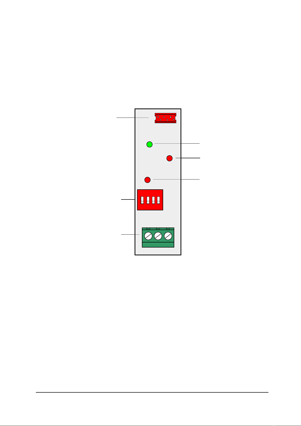
For a convenient integration into VISY-Command, the printed circuit board (PCB) of the
VISY-ICI 485 is mounted on a module carrier for subsequent installation on DIN rails.
2Installation
2.1 Safety precautions
The following safety precautions must be observed during installation of the VISY-ICI 485
communications adapter:
•The VISY-ICI 485 is designed for operation only with the VI-… interface card.
•Modifications to the VISY-ICI 485 are prohibited without the prior consent of the
manufacturer.
•The installation and configuration of the VISY-ICI 485 communications adapter
must be carried out only by expert, authorised personnel. Specialised knowledge
must be obtained by regular training.
•Operators, installers and service technicians must comply with all applicable safety
regulations. This also applies to any local safety regulations and accident
prevention regulations not stated in this technical documentation.
The safety instructions in this manual are labelled as follows:
If you do not observe these safety instructions, the risk of an accident
exists or the VISY-X system could be damaged.
Useful information in these instructions, that should be observed, is
printed in italics and marked with this symbol.

VISY-ICI 485 Page 5/11
2.2 Assembly
The VISY-ICI 485 is designed to be mounted on the DIN rail only.
Hold the module carrier of the VISY-ICI 485 at an angle to the rail and fit the mounting
foot onto the rail in such a way that one side of the module carrier is secured. Then press
the other side of the module carrier onto the rail until this side snaps into place and the
module carrier is firmly locked.
Figure 1: Assembly
The VISY-ICI 485 can be used only in conjunction with the VI-...
interface card (version VI-4 or later).
Mount the VISY-ICI 485 to the left of the VI-… interface card
on the DIN
rail.
The module carrier can be released from the DIN rail only by prising out
the mounting foot with a screwdriver.
VISY-ICI 485
VI-4 interface card

Page 6/11 VISY-ICI 485
2.3 Connections, LEDs and DIP switch
The VISY-ICI 485 has one connection for power supply and communication and another
one for connecting VISY-Input 8 and VISY-Output 4. Operating states are indicated by
three light-emitting diodes (LEDs). The connections and LEDs are arranged as follows:
Figure 2: Connections, LEDs and DIP switch
2.4 Connection to the VI-... interface card
Connect the VISY-ICI 485 to the VI-... interface card using the 6-pole ribbon cable
supplied (see Fig. 1). This ribbon cable provides the power supply and the data
communication link to the VISY-ICI 485.
Transmit LED
(red)
Power supply LED
(green)
Receive LED
(red)
DIP switch
Power supply
and communication
(from the VI-... interface card)
GND A B
O
N
1 2 3 4
Screw terminal
for connecting
VISY-Input 8 / VISY-Output
4

VISY-ICI 485 Page 7/11
2.5 Connecting VISY-Input 8 / VISY-Output 4
The VISY-ICI 485 supports the simultaneous operation of up to eight VISY-Input 8 and
eight VISY-Output 4 components. The components are connected to terminal A, B and
GND of the 3-pole screw terminal (galvanically isolated interface). An RS-485 network is
formed when the components are operated in conjunction with the VI-... interface card
(also connected to the VISY-ICI 485). The optimum configuration for the RS-485 network
is a linear topology (daisy chaining of all network subscribers). Ring or star topologies
should be avoided.
For the wiring of VISY-Input 8 / VISY-Output 4 components, a 3-core cable including
signal ground (GND) is recommended in order to improve immunity to interference.
Figure 3: Connecting VISY-Input 8 / VISY-Output 4
If shielded lines are used, the shield should be placed on the PE connection to prevent
interference coupling. If the shield cannot be fitted on both sides, it is possible to work
with a shield fitted to one side in the VISY-Command.
If shielded lines are used, do not place the line shield on signal
ground (GND).
Please note that the longer the line length, the greater the probability of
equipotential currents flowing through a line shield earthed on both sides.
Where necessary, an additional equipotential bonding conductor must be
provided between the connected devices in accordance with local rules
and regulations.
GND A B
GND A B
GND A B
VISY-ICI screw terminal
VISY-Input 8/ Output 4

Page 8/11 VISY-ICI 485
2.6 Power supply LED
The power supply LED lights up green whenever the VISY-ICI 485 is being supplied with
power. For location, see Fig. 2.
LED (green)
Meaning
on
VISY-ICI 485 supplied with power
off
VISY-ICI 485 not supplied with power
Table 1: Power supply LED
2.7 Communication LEDs
The two communication LEDs light up red whenever data are being transmitted or
received. For locations, see Fig. 2.
LED (red)
Meaning
on
Transmitting/receiving data
off
Not transmitting/receiving data
Table 2: Communication LEDs

VISY-ICI 485 Page 9/11
3Configuration
3.1 RS-485 network – bias and termination
Using the DIP switches, it is possible to bias the communication lines with a defined rest
potential and activate the terminating impedances.
By default, a bias is applied to the RS-485 network in order to improve reliability of
communication.
Under normal circumstances, communication in the RS-485 network should be
troublefree without the need for terminating impedance activation because the data rate
is relatively low.
The following table shows the possible functions depending on DIP switch configuration:
DIP switch
Function
1
2
3
4
OFF
OFF
OFF
OFF
no termination and no bias
ON
OFF
OFF
OFF
with series termination 120 Ω/ 100 nF
ON
OFF
OFF
ON
with termination resistance 120 Ω
OFF
ON
ON
OFF
with bias (factory default)
ON
ON
ON
OFF
with series termination 120 Ω/ 100 nF and bias
ON ON ON ON
with termination resistance 120 Ωand bias
Table 3: DIP switch
All switch positions not shown in the table are unauthorised and will
result in communication faults.
3.2 Reference to more detailed instructions
As is customary for the VISY-X System, all VISY-Input 8 / VISY-Output 4 components to
be connected need to be configured using the VISY-Setup configuration software. You
will find detailed information of the components and their configuration in the following
instruction manuals:
•Technical Documentation VISY-Setup 4 (English) – Art. No. 207158
•Technical Documentation VISY-Input 8 (English) – Art. No. 207166
•Technical Documentation VISY-Output 4 (English) – Art. No. 207131

Page 10/11 VISY-ICI 485
4Technical data
Ambient temperature:
0 °C to +40 °C
Power supply:
5 VDC,
≤
35 mA (from the VI-... interface card), connection
cable included
Serial interface:
RS-485, galvanically isolated, 3-pole screw terminal with
signal ground (GND),
for connecting VISY-Input 8 / VISY-Output 4
Operation indicator:
green LED
Communication indicator:
red LEDs: one for transmit, one for receive
Housing:
module carrier for mounting on DIN rails
Dimensions:
h 76 x w 24 x d 47 [mm]
5List of figures
Figure 1: Assembly..........................................................................................................5
Figure 2: Connections, LEDs and DIP switch.....................................................................6
Figure 3: Connecting VISY-Input 8 / VISY-Output 4 .........................................................7
6List of tables
Table 1: Power supply LED ..............................................................................................8
Table 2: Communication LEDs.........................................................................................8
Table 3: DIP switch..........................................................................................................9


FAFNIR GmbH
Schnackenburgallee 149 c
22525 Hamburg
Germany
Tel.: +49 / 40 / 39 82 07–0
Fax: +49 / 40 / 390 63 39
E-mail: info@fafnir.com
Web: www.fafnir.com
Table of contents
Other fafnir Adapter manuals