FAG PUMP1000-4L-CONTROL User manual

Hand pump
PUMP1000-4L-CONTROL
User manual

2
BA 20
Schaeffler Group Industrial
Safety guidelines and symbols
High product safety
Our products correspond to the current level of research and
technology. If the bearing arrangement is designed correctly,
the products are handled and fitted correctly and as agreed and
if they are maintained as instructed, they do not give rise to any
direct hazards.
Follow instructions
This publication describes standard products.
Since these are used in numerous applications, we cannot make
a judgement as to whether any malfunctions will cause harm to
persons or property.
It is always and fundamentally the responsibility of the designer
and user to ensure that all specifications are observed and that all
necessary safety information is communicated to the end user.
This applies in particular to applications in which product failure and
malfunction may constitute a hazard to human beings.
Definition of guidelines
and symbols
The warning and hazard symbols are defined along the lines of
ANSI Z535.6–2006.
The meaning of the guidelines and symbols is as follows:
Warning
If these safety guidelines are not observed, death or serious injury
may occur.
If these safety guidelines are not observed, damage or
malfunctions in the product or the adjacent construction will occur.
Note
There follows additional or more detailed information that must be
observed.
Numbers within a circle are item numbers.

Schaeffler Group Industrial BA 20 3
Page
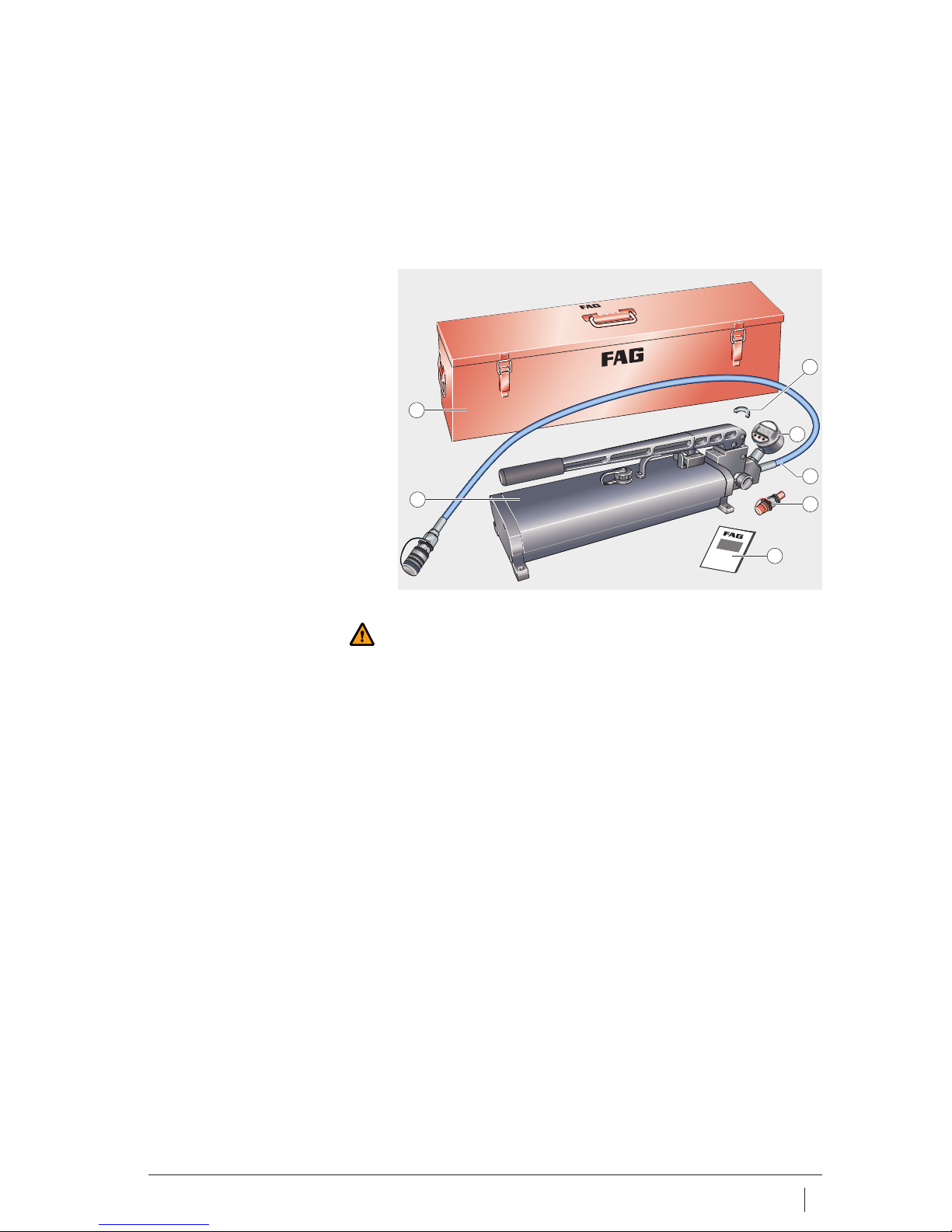
Features Scope of delivery ....................................................................... 5
Design and
safety guidelines
Intended purpose ...................................................................... 6
Qualified personnel................................................................... 6
Protective equipment ................................................................ 6
Hydraulic oil .............................................................................. 7
Maximum pressure.................................................................... 7
Ambient conditions ................................................................... 7
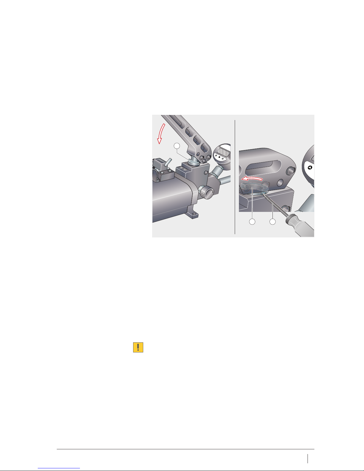
Initial operation Checking the hand pump........................................................... 8
Setting the stroke volume.......................................................... 9
Spacer ring .......................................................................... 9
Mounting the spacer ring ..................................................... 9
Dismounting the spacer ring ................................................ 9
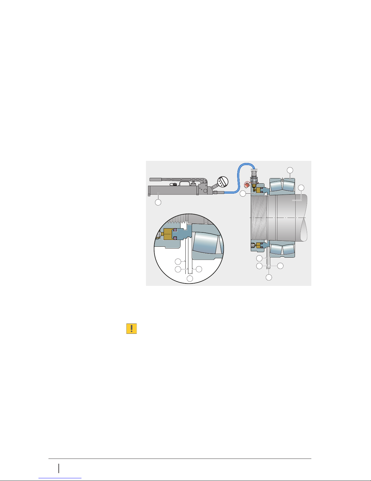
Operation Mounting the rolling bearing...................................................... 10
Mounting the hydraulic nut........................................................ 10
Connecting the hand pump ....................................................... 11
Venting the hand pump ....................................................... 11
Connection .......................................................................... 11
Venting the hydraulic nut........................................................... 11
Setting the start position ........................................................... 12
Determining the start pressure............................................. 12
Building up the start pressure.............................................. 12
Setting the end position ............................................................ 13
Determining the number of strokes ...................................... 13
Moving the rolling bearing to the end position ..................... 14
Dismounting the hand pump ..................................................... 14
Releasing the pressure ........................................................ 14
Removing the hand pump .................................................... 14
Maintenance ............................................................................. 15
Changing the oil................................................................... 15
Cleaning the tank................................................................. 15
Hand pump

4BA 20 Schaeffler Group Industrial
Page
Technical data Ordering designation................................................................. 16
EU Declaration of Conformity..................................................... 17
Digital manometer Features .................................................................................... 18
Operation.................................................................................. 18
Control keys ........................................................................ 18
Control diagram................................................................... 19
Maintenance ............................................................................. 20
Changing the battery ........................................................... 20
Dismantling......................................................................... 20
Mounting............................................................................. 20
Technical data........................................................................... 21
Ordering designations............................................................... 21
Troubleshooting ................................................................................................. 22
Value table Displacement distance, number of strokes................................ 24
Hand pump

Schaeffler Group Industrial BA 20 5
Features The hand pump and accessories are supplied in a sturdy metal case
made from sheet steel. The metal case and parts should be checked
immediately for any damage during transit. The carrier should be
informed of any damage without delay.
Scope of delivery The items included in delivery are shown in Figure 1.
Warning
If the hand pump or accessories are damaged, they must not be
used. Do not attempt to carry out repairs. Any repair work required
should be carried out by Schaeffler KG, Schweinfurt.
Metal case
Hand pump
Spacer ring (half ring),
HYDNUT50 to 150
Digital manometer
High pressure hose
with coupling sleeve
Coupling nipple
User manual
Figure 1
Scope of delivery
1
2
3
5
4
7
6
00015F98
Hand pump

6BA 20 Schaeffler Group Industrial
Hand pump
Design and
safety guidelines
Intended purpose The hand pump PUMP1000-4L-CONTROL is used to operate
FAG hydraulic nuts. These are used to mount rolling bearings on
a tapered seat, Figure 2.
Note
The hand pump can also be used for dismounting,
see BA 007, FAG Hand Pump Sets.
Qualified personnel The hand pump must only be used by qualified personnel.
A person defined as qualified personnel:
■is authorised to use the hand pump
■has all the necessary knowledge
■is familiar with the safety guidelines
■has read and understood this manual.
Protective equipment Protective equipment is intended to protect personnel against
health hazards.
When working with the hand pump, the following protective
equipment must be used at all times:
■protective goggles
■gloves or oil-based cream.
Tapered seat
Rolling bearing
Hydraulic nut
Hand pump
Figure 2
Mounting
3
2
1
4
00015F99

Schaeffler Group Industrial BA 20 7
Hydraulic oil The only hydraulic oils that can be used are:
■any hydraulic oils with a viscosity of 32 mm2/s at +40 °C.
Only clean hydraulic oil should be used.
If the oil is not clean, this may lead to blockage of the filter fitted.
Warning
Hydraulic oil can cause irritation to skin and respiratory passages.
Skin contact should therefore be avoided, vapours and fumes
should not be inhaled. Eyes must be protected against hydraulic oil.
Maximum pressure The hand pump delivers a pressure of up to 1000 bar. The maximum
pressure that can be used with a hydraulic nut is 800 bar.
Warning
800 bar must never be exceeded.
The manometer must be monitored continuously during operation.
Ambient conditions The hand pump should be used under the following ambient
conditions:
■The surface underneath must be even and capable
of supporting loads
■Temperature: 0 °C to +60 °C
■Humidity: max. 90%, no condensation.
Ensure that the ambient conditions are maintained throughout
the operating period.

8BA 20 Schaeffler Group Industrial
Hand pump
Initial operation This manual describes the initial operation of the hand pump,
for information on the initial operation of hydraulic nuts
see BA 004, FAG Hydraulic Nuts.
Checking the hand pump Before any use, check the hand pump and the accessories to be
used, Figure 3.
The hand pump can only be put into operation if all the following
questions can be answered with “yes”:
■Is the hand pump free from corrosion, cracks and damage?
■Is the tank completely filled with a suitable hydraulic oil,
see page 7?
■Is the escape valve easy to move and free from damage?
■Is the battery in digital manometer in acceptable condition
(if not, see the section Changing the battery, page 20)?
■Is the high pressure hose free from damage and kinks?
■Is the high pressure hose suitable for at least 1000 bar?
■Is the required stroke volume set
(see the section Setting the stroke volume, page 9)?
Warning
If the hand pump or accessories are damaged, they must not be
used. Do not attempt to carry out repairs. Any repair work required
should be carried out by Schaeffler KG, Schweinfurt.
Hand pump
Tank
Tank lid
Escape valve
Spacer ring (half ring),
HYDNUT50 to 150
Digital manometer
High pressure hose
Figure 3
Checking for initial operation
2
1
3
4
5
7
6
00015F97

Schaeffler Group Industrial BA 20 9
Setting the stroke volume The stroke volume of the hand pump can be adjusted as a function
of the hydraulic nut used.
Spacer ring The spacer ring (half ring) restricts the stroke and thus reduces
the stroke volume. The volume without a spacer ring (half ring)
is 0,9 cm3 per stroke, when the spacer ring (half ring) is mounted,
0,2 cm3of hydraulic oil is pressed into the hydraulic nut on
a complete stroke.
The spacer ring (half ring) should be mounted when using:
■HYDNUT50 to HYDNUT150.
Mounting the spacer ring A small flat blade screwdriver is recommended as a mounting tool,
Figure 4:
■Insert the spacer ring (half ring) (position A, )
■Press the arm of the hand pump down almost to the stop
■Rotate the spacer ring (half ring) by 180° into position B, .
Dismounting the spacer ring ■Press the arm down almost to the stop
■Rotate the spacer ring (half ring) by 180° into position A,
■Move the arm upwards
■Remove the spacer ring (half ring).
Do not replace the spacer ring (half ring) during operation of
the pump. Any inaccuracies in the displacement distance can
damage the bearing.
Spacer ring (half ring),
position A
Spacer ring (half ring),
position B
Screwdriver
Figure 4
Spacer ring (half ring)
P
0 0 0 0
1
2 3
00015F9A

10 BA 20 Schaeffler Group Industrial
Hand pump
Operation The mounting operation begins with mounting of the rolling bearing
on the tapered seat, Figure 5. Slide the rolling bearing gently onto
the shaft or slide the mounting sleeve into the original position.
A suitable hydraulic nut is then screwed onto the shaft and the hand
pump is connected. The hand pump is then operated until
the pressure to reach the start position is achieved. The hand pump
is now operated (number of strokes in accordance with the table)
until the rolling bearing has been driven up the required
displacement distance and the end position is achieved.
The pressure is then released and the hydraulic oil flows back into
the pump, after which the pump can be removed.
Note
In order to avoid delays during mounting, we recommend that
the initial pressure and the number of strokes is determined before
the start of mounting.
Mounting the rolling bearing Slide the rolling bearing gently onto the shaft. In this way,
it is possible to avoid sliding the rolling bearing on further than
the start position.
If the rolling bearing is slid on further than the start position,
the radial clearance is too small.
Mounting the hydraulic nut Locate the hydraulic nut on the tapered shaft or withdrawal sleeve.
Screw a coupling nipple into the hydraulic nut.
Hand pump
Hydraulic nut
Rolling bearing
Tapered seat
Original position
Start position
Displacement distance
End position
Figure 5
Mounting
5
8
6
5
8
7
7
6
4
3
2
1
00015F9B

Schaeffler Group Industrial BA 20 11
Connecting the hand pump Check whether the spacer ring (half ring) should be mounted,
see the section Spacer ring, page 9. First mount or remove the
spacer ring (half ring) as necessary and the hand pump should only
be connected after this has been done.
Warning
Only use the hand pump if the tank is completely filled with
hydraulic oil. Otherwise, air may be sucked in and compressed.
Venting the hand pump Before connecting the hand pump to the hydraulic nut,
vent the hand pump, Figure 6:
■Provide a collection container
(not included in the delivery)
■Screw the coupling nipple and sealing ring into
the hydraulic nut
■Place the hand pump on a rigid, horizontal surface,
since it is only possible to prevent air being sucked in when
the hand pump is horizontal
■Close the aeration screw completely,
then open it (one revolution)
■Close the escape valve
■Hold the high pressure hose vertically upwards
■Operate the hand pump until oil emerges without air bubbles.
Connection ■Fit the sleeve on the coupling nipple .
Warning
The high pressure hose must be suitable for a pressure of at least
1000 bar. Do not extend the arm of the hand pump. Check whether
the sleeve and coupling nipple are completely coupled.
Observe a minimum bending radius for the high pressure hose of
70 mm.
Venting the hydraulic nut Operate the hand pump until the hydraulic nut is completely vented,
see BA 004, FAG Hydraulic Nuts.
Coupling nipple
Sealing ring
Hydraulic nut
Sleeve
Collection container (hydraulic oil)
High pressure hose
Escape valve
Aeration screw
Figure 6
Venting the hand pump
78
2
3
1
5
6
4
00015F9C

12 BA 20 Schaeffler Group Industrial
Hand pump
Setting the start position The rolling bearing is displaced from the original position to the start
position. The hand pump is of a twin stage design.
At low pressure, a large quantity of oil is pressed into the hydraulic
nut, while above 10 bar this quantity is significantly smaller,
see the section Technical data, page 21.
Determining the start pressure The start pressure can be determined, for example,
using the Schaeffler software FAG Mounting Manager.
A user manual for the software is available on the Internet.
After calling up FAG Mounting Manager, the necessary data are
entered, Figure 7. The start pressure for reaching the start position
is then displayed.
Warning
Do not loosen the connectors on the hand pump if the unit is still
pressurised. Do not add any more oil.
Building up the start pressure Once the start pressure has been built up, the rolling bearing is in
the start position, Figure 5, page 10.
Keep the aeration screw open (one revolution):
■Close the escape valve, Figure 3 , page 8
■Set the digital manometer to zero, then monitor continuously
■Operate the hand pump until the start pressure is reached.
Do not exceed the start pressure. If the start pressure is exceeded,
the bearing must be dismounted and then remounted.
Internet address
Designation of bearing
Start pressure
Displacement distance
Figure 7
FAG Mounting Manager
00016047
1
2
3
4

Schaeffler Group Industrial BA 20 13
Setting the end position The end position is reached when the rolling bearing has been
moved the displacement distance. The displacement distance can
be read off, for example, in FAG Mounting Manager.
Determining the number of strokes The number of strokes can be read off on the basis of
the displacement distance and the hydraulic nut used, Figure 8,
and the value table, starting from page 24.
Example The following hydraulic nut is used for mounting of bearings:
■HYDNUT160.
When using HYDNUT160, any spacer ring present must be
dismounted, see the section Spacer ring, page 9.
The software FAG Mounting Manager determines the displacement
distance as follows:
■0,94 mm.
The next highest displacement distance is 1,01 mm and the number
of strokes is as follows, see the value table:
■10 strokes for mounting with hydraulic support
■12 strokes for mounting without hydraulic support.
Next highest displacement distance
Number of strokes
Figure 8
Value table, excerpt
160 smm 0,52 0,57 0,63 0,69 0,76 0,84 0,92 1,01 1
x1– 5 6 6 7 7 8 9 10 11
x2– 6 7 7 8 9 10 10 12 13
170 smm 0,55 0,61 0,67 0,73 0,81 0,89 0,97 1,07 1
x1– 6 6 7 8 9 9 10 11 13
x2– 7 7 8 9 10 11 12 13 15
180 smm 0,57 0,63 0,69 0,76 0,83 0,92 1,01 1,11 1
x1– 7 7 8 9 10 11 12 13 14
x2– 8 8 9 10 11 12 13 15 16
190 smm 0,61 0,67 0,74 0,81 0,89 0,98 1,08 1,19 1
x1– 8 9 10 10 12 13 14 15 17
x2– 9 10 11 12 13 15 16 18 19
200 smm 0,64 0,7 0,77 0,85 0,94 1,03 1,13 1,25 1
x1– 9 10 11 12 13 14 16 17 19
x2–10 11 12 14 15 16 18 20 22
210 smm 0,7 0,77 0,85 0,93 1,02 1,13 1,24 1,36 1
x1–11 12 13 14 15 17 19 20 23
x2–12 13 15 16 18 19 21 23 26
220 smm 0,7 0,77 0,85 0,93 1,02 1,13 1,24 1,36 1
x
1
–11 12 14 15 16 18 20 22 24
1
2
00016064

14 BA 20 Schaeffler Group Industrial
Hand pump
Moving the rolling bearing
to the end position
The hand pump is operated to bring the rolling bearing into the end
position, Figure 9.
Warning
800 bar must not be exceeded. Do not loosen the connectors on
the hand pump if the unit is still pressurised.
Do not add any more oil.
Keep the aeration screw open (one revolution):
■Close the escape valve , set the stroke counter to 0
■Monitor the digital manometer
■Move the hand pump from the upper stop to the lower stop
until the stroke counter shows the number of strokes.
Operate the escape valve by hand only. On each occasion,
the arm must be moved up to the upper stop and then down.
Do not exceed the number of strokes. If the number of strokes is
exceeded, the bearing must be dismounted and then moved back
to the start position.
Dismounting the hand pump Before the hand pump is removed, it must be unpressurised.
Releasing the pressure ■Slowly open the escape valve
■Monitor the digital manometer .
Removing the hand pump ■Once the unit is unpressurised, remove the sleeve from
the coupling nipple
■Close the sleeve using the end cap .
Escape valve
Digital manometer
High pressure hose
End cap
Sleeve
Coupling nipple
Hydraulic nut
Upper stop
Lower stop
Stroke counter
Figure 9
End position, dismounting
2
31
10
7
5
6
8
9
4
00015F9D

Schaeffler Group Industrial BA 20 15
Maintenance The use of unsuitable replacement parts and oils can damage
the hand pump and may lead to hazards occurring for the user.
Always use original replacement parts sets from Schaeffler KG.
Only use oils recommended by us, see the section Hydraulic oil,
page 7.
Changing the oil Check the hydraulic oil six months after the last oil change.
Replace contaminated oil.
One year after the last oil change, replace the oil even if it is not
contaminated:
■Empty the tank completely
■Check the tank and clean it if necessary
■Fill the tank completely with fresh oil, pump 50 times,
then fill up with fresh oil.
Note
Dispose of oil, contaminated cloths and similar materials in
the correct manner.
Cleaning the tank Clean the tank if there are stubborn deposits on the walls of
the tank:
■Empty the tank completely
■Fill the tank with petroleum ether
■Rock the filled tank
■Empty the tank completely
■Vent the tank.
Note
Dispose of petroleum ether, contaminated cloths and similar
materials in the correct manner.

16 BA 20 Schaeffler Group Industrial
Hand pump
Technical data
Hand pump
Ordering designations Replacement parts, Figure 10 and
table Ordering designation PUMP1000-4L-CONTROL.
Ordering designation
PUMP1000-4L-CONTROL
Component Technical data
Threaded connector G1/4
Oil container capacity 4l
Delivery volume ⬍10 bar 4cm
3per stroke with spacer ring (half ring);
18 cm3per stroke without spacer ring (half ring)
Delivery volume ⬎10 bar 0,2 cm3per stroke with spacer ring (half ring);
0,9 cm3per stroke without spacer ring (half ring)
Maximum oil pressure 1000 bar
Mass ⬇24 kg (including metal case)
Pump body
Oil container
Digital manometer
Spacer ring (full ring)
Spacer ring (half ring)
Stroke counter
Wear parts (set)
Figure 10
Replacement parts
OPENCLOSE
2
1
3
4
5
67
00016066
Component Ordering designation
Complete hand pump PUMP1000-4L-CONTROL
(incl. digital manometer in metal case)
Pump body PUMP1000-4L.BODY
Oil container PUMP1000-4L.TANK
Digital manometer PUMP1000.MANO-DIGI
Spacer ring (full ring) PUMP1000-4L-CONTROL.RING-0,2ML
Spacer ring (half ring) PUMP1000-4L-CONTROL.RING-0,9ML
Stroke counter PUMP1000-4L-CONTROL.COUNTER
Wear parts PUMP1000-4L.SPARE-KIT

Schaeffler Group Industrial BA 20 17
Hand pump
EU Declaration of Conformity Declaration of Conformity for hand pump PUMP1000-4L-CONTROL.
Figure 11
EU Declaration of Conformity
0001645D

18 BA 20 Schaeffler Group Industrial
Hand pump
Digital manometer The digital manometer PUMP1000-4L-CONTROL.MANO is part of
the hand pump and is already mounted when the hand pump is
supplied.
Features A ceramic sensor records the pressure and shows the value on
a four digit LED display. The accuracy is 0,5%.
The manometer is powered by a 9 V battery and has a peak value
memory.
Operation The device is operated using three membrane keys on the front,
Figure 12.
Switching on, switching off
Control keys The specific function of the key depends on whether the user
changes between different menu items or is within a single menu
item, see table.
Function of control keys
1)
When the value is confirmed, the system moves to the next menu item.
LED display
Down key
key
Up key
Battery symbol
Battery compartment cover
Hexagonal nut M27
Figure 12
Digital manometer
P
6
4
5
3
1
2
7
00015F65
Key Function
Device is switched on
2⫻Device is switched off
P
P
Key Select menu item Set value
Next menu item Reduce value
Previous menu item Increase value
–Confirm value1)
–Cancel value
Jump to function –
P
&
&
P

Schaeffler Group Industrial BA 20 19
Control diagram The navigation and setting options are shown in the control
diagram, Figure 13.
Footnotes for Figure 13 1)
Peak value memory off.
2)
Recording of maximum values.
3)
Recording of minimum values.
4)
Factory setting = 5.
5)
Automatic zeroing.
6)
New password, example.
LCD display
Peak value memory
Enter password
Automatic zeroing
Change password
Figure 13
Control diagram
&
P
P P
P
P
P
P
P
P
&
&
P
&
P
1⫻P = ON
1
2
3
4
5
2⫻P = OFF
1)
2)
3)
4)
6)
5)
00015F67

20 BA 20 Schaeffler Group Industrial
Hand pump
Maintenance Contaminated hydraulic oil can make maintenance necessary at
Schaeffler KG. If clean hydraulic oil is always used, maintenance is
restricted to changing the battery.
Changing the battery If the voltage of the battery falls below 7 Volt, the battery symbol
is shown, Figure 14. Lift the battery cover outwards and change
the battery.
Replace a used battery promptly by a fresh battery if the battery
symbol is shown. Replace a damaged battery cover and seal
promptly, since the ingress of hydraulic oil will destroy the device.
Always mount and dismount the digital manometer using
the hexagonal nut, never the housing, Figure 12, page 18!
Dismounting To replace a digital manometer that is damaged or in need of
maintenance:
■Ensure that the hand pump is unpressurised
■Unscrew the digital manometer (right hand thread) using
a wrench (A/F27).
Mounting To mount a new or repaired digital manometer:
■Use a new sealing ring, Figure 12, page 18
■Mount the digital manometer (right hand thread) using
a wrench (A/F27).
Battery symbol
Battery cover
9V battery
Figure 14
Changing the battery
1
2
3
00015FA3
Table of contents
Other FAG Water Pump manuals
Popular Water Pump manuals by other brands

Pfeiffer Vacuum
Pfeiffer Vacuum HiPace 30 operating instructions

vacuubrand
vacuubrand RE 9 Instructions for repair

Wilo
Wilo Rexa UNI Installation and operating instructions

BBC Elettropompe
BBC Elettropompe ECOSOM 4/80 Instruction and installation manual

Xylem
Xylem Goulds AquaBoost VS instruction manual

Graco
Graco 19D873 manual

Rothenberger
Rothenberger ROAIRVAC R32 2.0 CL Instructions for use

Sagola
Sagola DM1/300 Instruction manual / spare parts list

Piusi
Piusi VISCOMAT 60/2 AC Installation, use and maintenance

evenes
evenes EV-ZUP 15 manual

Beretta
Beretta Hydro Unit M Installation and owner's manual

Meganex
Meganex MEG36300 instruction manual