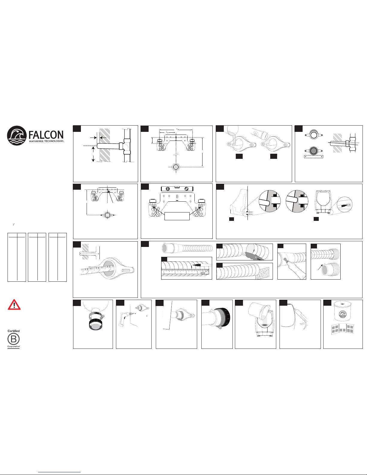
manuals.online logo
Brands
  1. Home
  2. •
  3. Brands
  4. •
  5. Falcon
  6. •
  7. Toilet
  8. •
  9. Falcon F1000 User manual

Falcon F1000 User manual

the drain line.
A.Hang the bowl on the bracket and check tail pipe alignment,
then remove the bowl and adjust the bracket as needed.
Re-hang and re-check bowl alignment with
Tail pipe should align with center of drain line.
B. Mark anchor holes then remove
bowl without moving hangerbracket.
A.Find the drain nipple depthon the Tube B. Cut the tube at the groove using a sharp
utility knife to ensure a square, flat cut.
C.Clean burrs from the cutend by using
emery paper.
D.Apply lubricant to the outside of the rubberbushing and
ribbed inside area.
E.Insert the tube andbushing with arrow tab at the top.
Applylubricant to tailpipe of housing.
USE UTILITY KNIFE TO CUT CAULK then
use a putty knife and mallet to remove the
bowl. Remove hangerbrackets, scrape off
caulk, and clean the wall.
.
DETERMINE THE DRAIN NIPPLE DEPTH
by measuring the distance betweenthe back
of the sanitary tee (orelbow) to the front
edge of the nipple.
IMPORTANT: Use adrain machine to remove
build-up inside pipes. Clean up to 25 feet deep
then flush with water to remove cutting debris.
Never install on copper DWV.
A.Clean face of existing wall flange.
B. Install the brass flangewith the clear inspection disc.
C.Slowly pour water into the drain.
D. Use a flashlight to check the pitch/slope No water
should be present in the inspection disc or nipple.
E.Remove flangeafter inspection.
ADJUST DRAIN TO ACHIEVE PITCH only if
standing water is present (code requires ¼"drop
per foot of drain line for proper pitch). Seal wall
according to code.
PLACE THE SEAL INTO THE
FLANGE withthe ribs facing
out. Install the flange with
washers and hex nuts, but
do not tighten completely.
HANG THE BOWL, inserting
tailpipe into bushing, then
install anchor screws with
washers.TIGHTEN FLANGE
BOLTS AND GEAR CLAMP.
POUR 5
GALLONS
OF WATER
as rapidly as
possible into housing
to ensure good flow and no
leaks or standing water.
INSTALL THE GEAR
CLAMP with screw
head at bottom, but
do not tighten.
DRILL HOLES with 5/16”
masonry bit for the lower
anchor screws and insert
plastic anchors.
The information in this document is
subject to change without notice.
©2015 Falcon Waterfree Technologies,
LLC. All rights reserved.
FalconWaterfree.com CAULK THE BOWL TO THE
WALL if there isgoodflow
andno leaks or standing
water.
CARTRIDGE
INSTALL
per the cartridge instruction
sheet.
•Check rough-in height to achieve 24"
rim height (17" rim height for ADA).
•Check slope. Downhill slope, per code,
is essential because waterfree urinals
require gravity flow for drainage.
•Check DWV material. Suitable materials
include cast iron, PVC, ABS, and
galvanized steel.
• Never install on copper DWV due to
copper’s susceptibility to corrosion.
•Shut off water supply and cap the nipple
with the ¾" chrome cap (provided).
•Measure drain nipple depth (in inches)
to find trim length(in inches)
•13
78" or more DO NOT CUT TUBE
•3¾" or less DO NOT USE TUBE
BEFORE STARTING INSTALLATION
TUBE CUTTING CHART
F1000
RETRO-FIT INSTALLATION
WATERFREE URINAL
service@falconwaterfree.com
CUSTOMERCARE
2" side cutter blade
Cut away wall
Lift drain line & brace
with mending plate
Install additional
screws here
INCORRECT
Not centered
CORRECT
Centered
11 10
12
CARTRIDGE
INSTRUCTIONS
CAUTIONAfter removing any urinal from the
drainline, it’s normal for certain naturally occurring
but potentially hazardous sewer gasesto escape
through the opening until the waterless cartridge
is installed properly into the waterless urinal. If you
need to leave an open drain line unattended after
removing the urinal from the wall, temporarily wedge paper towels or a
rag into the drainhole to reduce any outflow of sewer gases, and remove
the paper towels or rag prior to completing the urinal or cartridge
installation.Never smoke, have an open flame, or place your nose or
mouth near open drain lines or waterless urinal housings into which
a cartridge is not yet properly installed.You also can wearabreathing
mask when removing or installing any waterless urinal or cartridge to
reduce potential exposure to any such gases.
OR LESS TRIM
13 ¾" ¾"
13 ½ ½
13 ¼ ¼
13 1
12 ¾ 1¾
12 ½ 1½
12 ¼ 1¼
12 2
11 ¾ 2¾
11 ½ 2½
11 ¼ 2¼
11 3
10 ¾ 3 ¾
10 ½ 3 ½
OR LESS TRIM
10 ¼" 3 ¼"
10 4
9 ¾ 4 ¾
9 ½ 4 ½
9 ¼ 4 ¼
95
8 ¾" 5 ¾
8 ½ 5 ½
8 ¼ 5 ¼
86
7 ¾ 6 ¾
7 ½ 6 ½
7 ¼ 6 ¼
77
OR LESS TRIM
6 ¾" 7 ¾"
6 ½ 7 ½
6 ¼ 7 ¼
68
5 ¾ 8 ¾
5 ½ 8 ½
5 ¼ 8 ¼
59
4 ¾ 9 ¾
4 ½ 9 ½
4 ¼ 9 ¼
410
21½
Install plastic anchor
and screw here
15 16
4
14
7
3
13
9
6
2
11 1210
8
5
1
1234
Arrow
tab UP
1234
A
C
BDE
B
C D
AB
existing bearing rods
LEVEL THE BRACKET THEN MARK, drill and install
two additional plastic anchors and screws. If pre-
can be used, screws are
not necessary.
MEASURE & MARK THE ROUGH-IN is in-wall
drill hole, then install the hangerbracket with
one plastic anchor and screw.
carrier is not used. Use a 5/16” masonry bit to
Cutting Chart (left). Measure and mark the
specified trim length on the insert tube at
the nearest 1/4” groove.
310-209-7250
CARRIER STUD PLACEMENT If using in-wall
carrier, setbearing rods as shown above.
SET DRAIN LINE HEIGHT 16 ¾” from
finished floor (standard 24” rim) or 9¾” for
ADA installation. Threadednipple should
extend ½ to ¾”from wall.
TIGHTEN
COMPRESSION
NUT AND GEAR
CLAMP.
PLACE THE GEAR CLAMP
and compression nut onto
the housing tailpipe.
½" to ¾"
9¾" for ADA
installation
standard 24" rim
finished floor
16 ¾"
Drain
2½
6 ⁄
13 ⁄
21½
the drain line.
A.Hang the bowl on the bracket and check tail pipe alignment,
then remove the bowl and adjust the bracket as needed.
Re-hang and re-check bowl alignment with
Tail pipe should align with center of drain line.
B. Mark anchor holes then remove
bowl without moving hangerbracket.
A.Find the drain nipple depthon the Tube B. Cut the tube at the groove using a sharp
utility knife to ensure a square, flat cut.
C.Clean burrs from the cutend by using
emery paper.
D.Apply lubricant to the outside of the rubberbushing and
ribbed inside area.
E.Insert the tube andbushing with arrow tab at the top.
Applylubricant to tailpipe of housing.
.
DETERMINE THE DRAIN NIPPLE DEPTH
by measuring the distance betweenthe back
of the sanitary tee (orelbow) to the front
edge of the nipple.
A.Clean face of existing wall flange.
B. Install the brass flangewith the clear inspection disc.
C.Slowly pour water into the drain.
D. Use a flashlight to check the pitch/slope No water
should be present in the inspection disc or nipple.
E.Remove flangeafter inspection.
ADJUST DRAIN TO ACHIEVE PITCH only if
standing water is present (code requires ¼"drop
per foot of drain line for proper pitch). Seal wall
according to code.
HANG THE BOWL, inserting
tailpipe into bushing, then
install anchor screws with
washers.TIGHTEN FLANGE
BOLTS AND GEAR CLAMP.
POUR 5
GALLONS
OF WATER
as rapidly as
possible into housing
toensure good flow and no
leaks or standing water.
DRILL HOLES with 5/16”
masonry bit for the lower
anchor screws and insert
plastic anchors.
CAULK THE BOWL TO THE
WALL if there isgoodflow
andno leaks or standing
water.
INSTALL CARTRIDGE
per the cartridge instruction
sheet.
Cut away wall
Lift drain line & brace
with mending plate
Install additional
screws here
INCORRECT
Not centered
CORRECT
Centered
11 10
12
CARTRIDGE
INSTRUCTIONS
21½
Install plastic anchor
and screw here
15 16
4
14
7
3
13
9
6
2
11 1210
8
5
1
1234
Arrow
tab UP
1234
A
C
BDE
B
C D
AB
existing bearing rods
LEVEL THE BRACKET THEN MARK, drill and install
two additional plastic anchors and screws. If pre-
can be used, screws are
not necessary.
MEASURE & MARK THE ROUGH-IN is in-wall
drill hole, then install the hangerbracket with
one plastic anchor and screw.
carrier is not used. Use a 5/16” masonry bit to
Cutting Chart (left). Measure and mark the
specified trim length on the insert tube at
the nearest 1/4” groove.
The information in this document is
subject to change without notice.
©2015 Falcon Waterfree Technologies,
LLC. All rights reserved.
FalconWaterfree.com
•Check rough-in height to achieve 24"
rim height (17" rim height for ADA).
•Check slope. Downhill slope, per code,
is essential because waterfree urinals
require gravity flow for drainage.
•Check DWV material. Suitable materials
include cast iron, PVC, ABS, and
galvanized steel.
• Never install on copper DWV due to
copper’s susceptibility to corrosion.
•Shut off water supply and cap the nipple
with the ¾" chrome cap (provided).
•Measure drain nipple depth (in inches)
to find trim length(in inches)
•13
78" or more DO NOT CUT TUBE
•3¾" or less DO NOT USE TUBE
BEFORE STARTING INSTALLATION
TUBE CUTTING CHART
F1000
NEW CONSTRUCTION INSTALLATION
WATERFREE URINAL
310-209-7250
service@falconwaterfree.com
CUSTOMERCARE
CAUTIONAfter removing any urinal from the
drainline, it’s normal for certain naturally occurring
but potentially hazardous sewer gasesto escape
through the opening until the waterless cartridge
is installed properly into the waterless urinal. If you
need to leave an open drain line unattended after
removing the urinal from the wall, temporarily wedge paper towels or a
rag into the drainhole to reduce any outflow of sewer gases, and remove
the paper towels or rag prior to completing the urinal or cartridge
installation.Never smoke,have an open flame, or place your nose or
mouth near open drain lines or waterless urinal housings into which
a cartridge is not yet properly installed.You also can wearabreathing
mask when removing or installing any waterless urinal or cartridge to
reduce potential exposure to any such gases.
OR LESS TRIM
13 ¾" ¾"
13 ½ ½
13 ¼ ¼
13 1
12 ¾ 1¾
12 ½ 1½
12 ¼ 1¼
12 2
11 ¾ 2¾
11 ½ 2½
11 ¼ 2¼
11 3
10 ¾ 3 ¾
10 ½ 3 ½
OR LESS TRIM
10 ¼" 3 ¼"
10 4
9 ¾ 4 ¾
9 ½ 4 ½
9 ¼ 4 ¼
95
8 ¾" 5 ¾
8 ½ 5 ½
8 ¼ 5 ¼
86
7 ¾ 6 ¾
7 ½ 6 ½
7 ¼ 6 ¼
77
OR LESS TRIM
6 ¾" 7 ¾"
6 ½ 7 ½
6 ¼ 7 ¼
68
5 ¾ 8 ¾
5 ½ 8 ½
5 ¼ 8 ¼
59
4 ¾ 9 ¾
4 ½ 9 ½
4 ¼ 9 ¼
410

Popular Toilet manuals by other brands

Saniwise F8 user manual

Saniwise

Saniwise F8 user manual

DURAVIT SensoWash i operating instructions

DURAVIT

DURAVIT SensoWash i operating instructions

Croydex Ontario WL602086H manual

Croydex

Croydex Ontario WL602086H manual

Gordon Ellis & CO NOBI CLASSIC Instructions for use

Gordon Ellis & CO

Gordon Ellis & CO NOBI CLASSIC Instructions for use

MAINLINE ML100W INSTALLATION INSTRUCTIONS CARE AND MAINTENANCE

MAINLINE

MAINLINE ML100W INSTALLATION INSTRUCTIONS CARE AND MAINTENANCE

Kohler S-TRAP K-23188T-ITHC installation instructions

Kohler

Kohler S-TRAP K-23188T-ITHC installation instructions

Geberit AquaClean Mera Comfort 146.210.11.1 installation manual

Geberit

Geberit AquaClean Mera Comfort 146.210.11.1 installation manual

Kohler REVE K-24766T-S installation instructions

Kohler

Kohler REVE K-24766T-S installation instructions

Helvex OP RIVOLI PLUS installation guide

Helvex

Helvex OP RIVOLI PLUS installation guide

essential Lily EC1014 manual

essential

essential Lily EC1014 manual

noken Smart Line 100159543-N386000053 manual

noken

noken Smart Line 100159543-N386000053 manual

BATHCO Oropesa 4565 manual

BATHCO

BATHCO Oropesa 4565 manual

clivus multrum NL2 owner's manual

clivus multrum

clivus multrum NL2 owner's manual

Kohler CABERNET WATER-GUARD K-3401 installation instructions

Kohler

Kohler CABERNET WATER-GUARD K-3401 installation instructions

SUNWIND Superstolen 700085 user manual

SUNWIND

SUNWIND Superstolen 700085 user manual

Kohler VEIL+ K-5401T-3-0 Homeowner's guide

Kohler

Kohler VEIL+ K-5401T-3-0 Homeowner's guide

Uberhaus CALISI instructions

Uberhaus

Uberhaus CALISI instructions

verotti IN.200X user manual

verotti

verotti IN.200X user manual

manuals.online logo
manuals.online logoBrands
  • About & Mission
  • Contact us
  • Privacy Policy
  • Terms and Conditions

Copyright 2025 Manuals.Online. All Rights Reserved.