Fast & Fluid Management GA350 User manual

V. 1.0 www.fast-fluid.com
www.fluidman.com
Manual GA350

2
© Fast & Fluid Management B.V.
This manual or parts thereof may not be reproduced, stored in a retrieval system, or transmitted, in any form or by any means,
electronic, mechanical, photocopying, recording, nor otherwise, without the prior written permission of Fast & Fluid
Management B.V.
This manual could contain technical inaccuracies or typographical errors.
Fast & Fluid Management B.V. reserves the right to revise this manual from time to time in the contents thereof without the
obligation of Fast & Fluid Management B.V. to notify any person of such revision or change.
Details and values given in this manual are average values and have been compiled with care. They are not binding, however,
and Fast & Fluid Management B.V. disclaims any liability for damage or detriments suffered as a result of reliance on the
information given herein or the use of products, processes or equipment to which this manual refers. No warranty is made that
the use of the information or of the products, processes or equipment to which this manual refers will not infringe any third
party’s patents or rights. The information given does not release the user from making their own experiments and tests.

Table of Contents GA350 V. 1.0
3
Table of Contents
1 About this manual.........................................................................................................5
1.1 How to work with the manual............................................................................................5
1.2 Record of changes............................................................................................................5
2 Safety .............................................................................................................................7
2.1 Intended use .....................................................................................................................7
2.2 Liability..............................................................................................................................7
2.3 User qualification for installation .......................................................................................7
2.4 CE certification..................................................................................................................7
2.5 Safety symbols on the machine........................................................................................8
2.6 Safety symbols in the manual...........................................................................................8
2.7 Disposal of the machine ...................................................................................................9
3 Operator manual .........................................................................................................11
3.1 Description......................................................................................................................11
3.1.1 Overview of the machine ....................................................................................11
3.1.2 Overview of the control panel .............................................................................12
3.1.3 Type plate: serial number ...................................................................................12
3.1.4 Type plate: details...............................................................................................12
3.2 Operation ........................................................................................................................13
3.2.1 Turning on the machine - if cradle is in correct position .....................................13
3.2.2 Turning on the machine - if cradle is not in correct position ...............................13
3.2.3 Turning on the machine when the machine is in hybernation.............................13
3.2.4 Normal mix procedure ........................................................................................13
3.2.5 Placing the can ...................................................................................................14
3.2.6 Start the machine................................................................................................16
3.2.7 Remove the can..................................................................................................17
3.2.8 Stop the operation manually...............................................................................17
3.2.9 Choose the mix speed ........................................................................................18
3.2.10 Choose the mix time ...........................................................................................18
3.2.11 Adjust default mix time........................................................................................19
3.3 General cleaning: after every operation..........................................................................19
3.4 Periodic maintenance: weekly ........................................................................................19
3.5 Periodic maintenance: monthly.......................................................................................19
3.6 Remove spilled paint ......................................................................................................20

Table of Contents GA350 V. 1.0
4
4 Installation ...................................................................................................................21
4.1 Unpack the machine .......................................................................................................21
4.1.1 Remove the cardboard .......................................................................................21
4.1.2 Remove the plastic protection and foil................................................................21
4.1.3 Remove the transport brackets...........................................................................22
4.1.4 Dispose of the packaging material......................................................................22
4.2 Put the machine in position.............................................................................................22
4.2.1 Move the machine from the pallet.......................................................................22
4.2.2 Move the machine to the final location ...............................................................22
4.2.3 Level the machine...............................................................................................23
4.3 Finish the installation ......................................................................................................23
5 Troubleshooting..........................................................................................................25
5.1 General troubleshooting procedure ................................................................................25
5.2 Contact service ...............................................................................................................25
5.3 Troubleshooting guide ....................................................................................................25
5.3.1 Errors ..................................................................................................................25
5.4 Reset after an emergency stop.......................................................................................25
5.5 Restart the machine........................................................................................................26
6 Technical data .............................................................................................................27
6.1 General specifications ....................................................................................................27
6.2 Dimensions and mass ....................................................................................................27
6.3 Ambient conditions .........................................................................................................27
6.4 Noise level ......................................................................................................................28
6.5 Safety classifications ......................................................................................................28
6.6 Electrical specifications...................................................................................................28
6.7 Electrical diagram ...........................................................................................................29

About this manual GA350 V. 1.0
5
1 About this manual
The manual shows the information necessary to:
-install
-operate
-perform basic maintenance
-correct small problems
The GA350 and all its versions are referred to in the manual as
the ’machine’.
This manual contains the original instructions. The original
language of the manual is English.
1.1 How to work with the manual
1. Familiarize yourself with the structure and content.
2. Read the safety chapter in detail and make sure you
understand all the instructions. See § 2.
3. Carry out the actions completely and in the given sequence.
1.2 Record of changes
/i
Edition Editor Check Date Description
1.0 MP MB/TB 05/2014 First edition

About this manual GA350 V. 1.0
6

Safety GA350 V. 1.0
7
2 Safety
2.1 Intended use
The machine is designed to mix paint in a can. Any other use of the machine is strictly forbidden.
2.2 Liability
Our machines and accessories are fully compliant with the CE regulations. Any modification can result in not
fulfilling the CE safety requirements and is therefore not allowed. Fast & Fluid Management B.V. will not accept
any responsibility in case of modifications to machines and/or accessories.
The mixer cannot be used in an environment where explosive vapours may occur (ATEX zone). Paints that
contain flammable solvents can be mixed, as long as they packed in a suitable UN approved container.
Fast & Fluid Management B.V. is not liable if you do not follow the rules below:
- Place machine in a well-lit and well ventilated room.
- Mind the minimal requirement of the building structure of the load capacity of the floor.
- Do not use a damaged machine. When you have doubts, contact your supplier. See § 5.1.
- Do not use extension cords.
- The machine is for indoors use only.
- Install and connect the machine according to the instructions in this manual.
- Observe all local safety regulations.
- Connect the machine to a grounded wall socket.
- Keep the machine in good condition. Make sure that defective parts are immediately replaced.
- This machine may only be used for commercial settings. The machine is not a household appliance.
- Make sure that the machine is installed as prescribed in this manual
- Replace parts only with original Fast & Fluid Management B.V. spare parts.
All maintenance beyond the scope of this manual must be carried out by a qualified service technician that Fast
& Fluid Management B.V. has trained and certified.
2.3 User qualification for installation
Only install the machine if you have written permission from the supplier of the machine.
2.4 CE certification
The machine is CE certified. This means that the machine complies with the essential requirements concerning
safety. The directives that have been taken into consideration in the design are available on www.fast-fluid.com.
WARNING
Read the manual before you install or use the machine. Failure to do so can
result in personal injury, death or property damage.
Safety GA350 V. 1.0
8
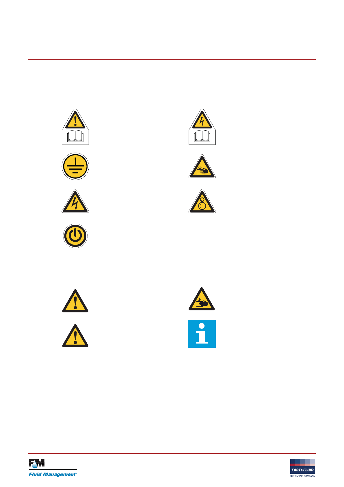
2.5 Safety symbols on the machine
/i
2.6 Safety symbols in the manual
/i
Read the manual. Electrical hazard. Read the manual.
Central earthing point. Pinch hazard.
Electrical hazard. Rotating parts.
On-Off
WARNING
Can cause personal injury.
WARNING
Pinch hazard.
CAUTION
Can cause damage to the machine.
Note
Shows further information.

Safety GA350 V. 1.0
9
2.7 Disposal of the machine
1. Sort the machine, the accessories and the packaging for
environmentally friendly recycling.
2. Do not dispose of the machine into domestic waste. Dispose
of the machine according to local regulations.

Safety GA350 V. 1.0
10

Operator manual GA350 V. 1.0
11
3 Operator manual
3.1 Description
3.1.1 Overview of the machine
A: Door
B: Casing
C: Control panel. See also § 3.1.2.
D: Emergency stop
E: Wheel
F: Adjustable foot
G: Can plate (bottom)
H: Can table
I: Drain orifice
J: Can plate (top)
K: Type plate. See also § 3.1.4.
L: Net entry
M: Main switch
A
D
C
E
E
M
F
B
J
G
H
I
K
L
M
Operator manual GA350 V. 1.0
12
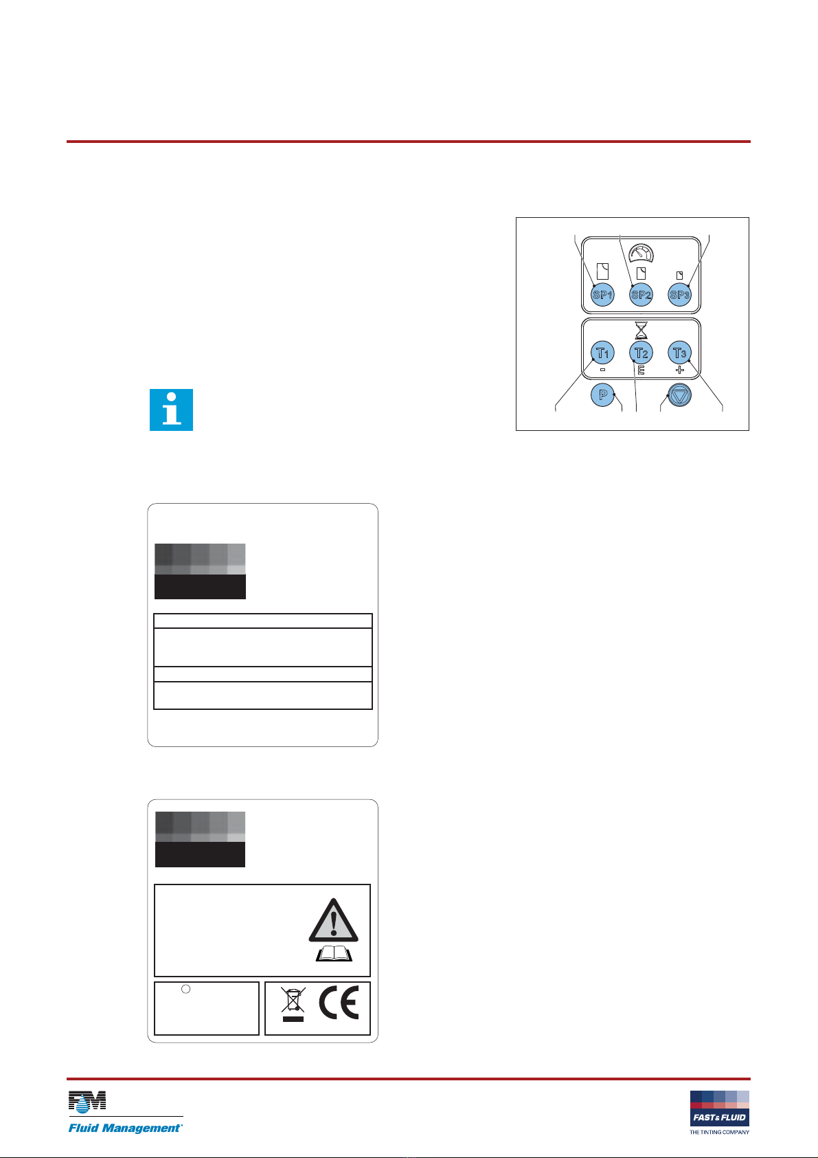
3.1.2 Overview of the control panel
A: SP1 key (mix speed 1)
B: SP2 key (mix speed 2)
C: SP3 key (mix speed 3)
D: T1 key (mix time 1)
E: T2 key (mix time 2)
F: T3 key (mix time 3)
G: Program key
H: Stop key
3.1.3 Type plate: serial number
3.1.4 Type plate: details
Note
The function of the T1 to T3 keys changes when you
adjust the default values of the machine.
See also § 3.2.9 and § 3.2.10.
A B C
D EG H F
Fast & Fluid Management B.V.
IDEX Dispensing
P.O. Box 220
2170 AE Sassenheim
The Netherlands
THE TINTING COMPANY
FAST FLUID
&
Model
XXXXX-XXX
Prod. Week XX-XXXX
Serial No.
XXXXX-XX-XXXXXX
Fast & Fluid Management B.V.
IDEX Dispensing
P.O. Box 220
2170 AE Sassenheim
The Netherlands
THE TINTING COMPANY
FAST FLUID
&
XXX
V
XX
Hz
XXX
W
Model XXXXX-XXX
Serial no. XXXXX-XX-XXXXXX
Prod. week XX-XXXX
Mass XXX XX
Fuse XX XX
Design
c
Made in XXXXXXXXX
Operator manual GA350 V. 1.0
13
3.2 Operation
3.2.1 Turning on the machine - if cradle is in correct position
1. Connect the power cable to the grounded wall socket.
2. Make sure that the emergency stop is released.
3. Set the Main switch to ‘ON’. When the machine is on, you
hear two ‘beeps’ and the display shows ‘rdY’.
4. Press any key. The machine is operational, the display shows
‘rdY’.
3.2.2 Turning on the machine - if cradle is not in correct position
1. Connect the power cable to the grouned wall socket.
2. Make sure that the emergency stop is released.
3. Set the Main switch to ‘ON’. When the machine is on, you
hear two ‘beeps’ and the display shows ‘...’.
4. Press any key. When the machine is operational, the display
shows ‘rdY’.
3.2.3 Turning on the machine when the machine is in hybernation
When the machine is in hybernation, the display shows ‘.’
1. Push the Stop key. When the machine is operational, the
display shows ‘rdY’.
2. Or immediately choose the correct speed and time key to start
the machine.
3.2.4 Normal mix procedure
1. Place the can. See § 3.2.5.
2. Clamp the can.
3. Choose the requested mix speed and time. See § 3.2.9 and
§ 3.2.10.
4. Start the machine, See § 3.2.6.
5. Wait till you hear "beep".
6. Remove the can. See § 3.2.7.
WARNING
Only push the emergency stop in the case of a safety emergency.
CAUTION
Make sure that the machine is empty or that a can is clamped.

Operator manual GA350 V. 1.0
14
3.2.5 Placing the can
Pull out the can table
1. Open the door.
2. Pull up the handle (A) to unlock the can table (B).
3. Pull out the can table until you hear a ‘click’. The can table is
locked.
Place the can
1. Put one or more cans (A) in the centre of the can table, or in
a pattern that has its gravitational centre in the middle of the
can table.
2. If the can plates are too close to each other, use the handles
to turn the upper can plate upwards until you can place the
can.
3. If you mix more than one can at the same time, make sure
that the can handles can not move. Use self-adhesive tape,
for example.
B
A
1
2
A A
A A
A
A
12
34
WARNING
It is possible that the can is heavy. Use the
correct lifting tool when appropriate. Obey the
local regulations.
CAUTION
Make sure that all cans have the same height.
Do not stack cans upon each other.

Operator manual GA350 V. 1.0
15
If you mix one can:
1. Retain the can handle with an elastic band or self-adhesive
tape.
Push the can table
1. Pull up the handle (A) to unlock the can table.
2. Push the can table (B) inwards until you hear a ‘click’. The can
table is locked.
Clamp can
1. Use the handles to move the can plates towards each other.
2. If you feel resistance, turn the upper can plate another quarter
turn.
B
A
B
A
1
2
1
2

Operator manual GA350 V. 1.0
16
3. Lift the handles and move the handles inwards.
4. Push the lock button to secure the handles.
5. Close the door.
3.2.6 Start the machine
1. Select the speed by pushing the SP1, SP2 or SP3 key. See
§ 3.2.9.
2. Select the mix time by pushing the T1, T2 or T3 key. See
§ 3.2.10.
3. The machine starts automatically.
1
2
1
2
3
Note
The display shows the time in seconds that
remain before you can open the door.
Note
While the machine operates, you can adjust
the mix speed with the SP1, SP2 and SP3
keys. The machine shows the chosen speed
every several seconds.
Note
While the machine operates, you can adjust
the mix time with the + and - keys.

Operator manual GA350 V. 1.0
17
3.2.7 Remove the can
1. Open the door.
2. Turn the lock button counterclockwise to loosen the handles.
3. Move the handles upwards.
4. Use the handles to unclamp the can.
5. Pull up the handle (A) to unlock the can table (B).
6. Pull out the can table until it is locked into the outer position.
7. Remove the elastic band.
8. Remove the can.
3.2.8 Stop the operation manually
1. Push the Stop key.
2. Wait until the door is unlocked. The display shows ‘rdY’.
3. If necessary, remove the can. See § 3.2.7.
1
22
2
1
B
A
1
2
Operator manual GA350 V. 1.0
18
3.2.9 Choose the mix speed
/i
1. While the machine operates, the display shows the last-
chosen speed every several seconds (SP1, SP2 or SP3).
2. Push a SP key to select the required speed.
3.2.10 Choose the mix time
/i
1. Push a T-key or combination to choose the mix time.
Note
You can choose the mix speed when the display
shows ‘rdY’.
Note
While the machine operates, you can adjust the mix
speed with the SP1, SP2 and SP3 keys. The
machine shows the chosen speed every several
seconds.
Note
If you choose the wrong speed, the machine will
adjust the speed automatically.The display will
show ’SCx’. The x is the new value for the speed.
Key Mix speed (Rpm) Recommended weight (Kg)
SP1 110 20-35
SP2 140 8 - 19
SP3 200 0 - 7
Key pushed Mix time [s]
T1 30
T2 120
T3 240
T1 + T2 at the same time 30 + 120 = 150
T1 + T3 at the same time 30 + 240 = 270
T2 + T3 at the same time 120 + 240 = 360
Note
The table shows the default values.
Operator manual GA350 V. 1.0
19
3.2.11 Adjust default mix time
1. At the same time, push the Program key and the T1, T2 or T3
key. Hold for 2 seconds.
2. Push the + or - key to adjust the mix time for T1, T2 or T3.
3. To save the new mix time, push the E-key.
4. If you do not want to save the new mix time, push the Stop
key.
3.3 General cleaning: after every operation
1. Clean the machine with a cloth and remove all spilled paint or
other liquid.
3.4 Periodic maintenance: weekly
1. Remove the paint. Refer to § 3.6.
2. Grease the spindles.
3.5 Periodic maintenance: monthly
1. Remove paint and dirty grease. Add new grease.
2. Grease the axle and other sliding parts.
Note
You can adjust the default mix time when the
display shows ‘rdY’.
CAUTION
Do not use cleaning agents based on organic
solvents to clean painted or plastic parts of the
machine.
CAUTION
Do not use cleaning agents based on organic
solvents to clean painted or plastic parts of the
machine.
WARNING
Check the MSDS of the Colorants about
personal protection measures required for
handling the colorant.
CAUTION
Do not use cleaning agents based on organic
solvents to clean painted or plastic parts of the
machine.

Operator manual GA350 V. 1.0
20
3.6 Remove spilled paint
Do this procedure when paint is spilled inside the machine.
1. Make sure that the machine is stopped. See § 3.2.6 or § 3.2.8.
2. Put a reservoir (A) below the drain orifice (B).
3. Remove the cap (C) from the drain orifice. The spilled paint
comes out of the machine.
4. Dispose of the spilled paint according to local regulations.
5. Install the cap to the drain orifice.
6. Clean the machine. See § 3.3.
C
B
A
B
CAUTION
Make sure that the reservoir is big enough to
hold all the spilled paint.
Table of contents
Other Fast & Fluid Management Mixer manuals


