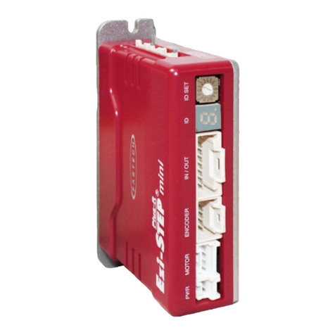
Fastech Ezi-servo plus-R User manual

www.fastech.co.kr
User Manual
Text
( Rev.08.06.23)

www.fastech.co.kr
2
1. Safety Pre-cautions
-Table of Contents -
1. Safety Pre-cautions ....................................................... 5
2. Specifications of the Drive ............................................... 8
2.1 Characteristic Table .................................................................. 8
2.2 Dimensions........................................................................... 11
3. Specifications of the Motor ...............................................12
3.1 EzM-20 Series........................................................................ 12
3.2 EzM-28 Series........................................................................ 13
3.3 EzM-35 Series........................................................................ 14
3.4 EzM-42 Series........................................................................ 15
3.5 EzM-56 Series........................................................................ 17
3.6 EzM-60 Series........................................................................ 19
3.7 EzM-86 Series........................................................................ 21
4. Characteristics of Motor Torque............................................22
4.1 Ezi-SERVO-PR......................................................................... 22
4.2 Ezi-SERVO PR-MI ...................................................................... 24
4.3 Ezi-SERVO-ALL........................................................................ 25
5. Configuration of the Controller............................................26
5.1 Combination of Motor and Drive ....................................................... 26
5.2 Controller Configurtion .............................................................. 31
5.3 External Wiring Diagram .............................................................. 34
6. External Name and Function Setting of Ezi-SERVO-PR .........................40
6.1 Appearance and Part Name ............................................................. 40
6.2 Status Display LED ................................................................... 41
6.3 Drive ID Switch Selection (SW1) ...................................................... 41
6.4 Communication Speed and Terminal Resistance Select Switch(SW2) ........................ 41
6.5 Motor Connection (CN3) ............................................................... 42
6.6 Encoder Connection (CN2) ............................................................. 42
6.7 Power Connection(CN4) ................................................................ 42

www.fastech.co.kr
3
1. Safety Pre-cautions
6.8 I/O Signal Connection (CN1) .......................................................... 42
6.9 Communication Connecttion (CN5) ...................................................... 43
7. External Name and Function Setting of Ezi-SERVO-PR-MI ......................44
7.1 Appearance and Part Name ............................................................. 44
7.2 Drive ID Switch Selection (SW1) and 7-segmant......................................... 44
7.3 Communication Speed and Terminal Resistance Select Switch(SW2) ........................ 44
7.4 Motor Connection (CN3) ............................................................... 45
7.5 Encoder Connection (CN2) ............................................................. 45
7.6 Power Connection(CN4) ................................................................ 45
7.7 I/O Signal Connection (CN1) .......................................................... 46
7.8 Communication Connection (CN5) ....................................................... 46
8. External Name and Function Setting of Ezi-SERVO-ALL42 / ALL56...............47
8.1 Appearance and Part Name ............................................................. 47
8.2 Terminal Resistance Select Switch(SW1) ............................................... 47
8.3 Drive ID Switch Selection (SW2) ...................................................... 47
8.4 Communication Speed Select Switch(SW3) ............................................... 47
8.5 I/O Signal Connection (CN1) .......................................................... 48
8.6 Power Connection(CN2) ................................................................ 48
8.7 Communication Connection (CN3, CN4) .................................................. 48
9. External Name and Function Setting of Ezi-SERVO-ALL60 ......................49
9.1 Appearance and Part Name ............................................................. 49
9.2 Terminal Resistance Select Switch(SW1) ............................................... 49
9.3 I/O Signal Connection (CN3) .......................................................... 49
9.4 Power Connection(CN1) ................................................................ 50
9.5 Communication Connection (CN5, CN6) .................................................. 50
10. Control I/O Signal .......................................................51
10.1 Signal Cabling (Ezi-SERVO-PR type) .................................................. 51
10.2 Signal Cabling (Ezi-SERVO-ALL type) ................................................. 52
10.3Connection Circuit ................................................................... 53
10.4 Input Signal........................................................................ 55
10.5 Output Signal....................................................................... 64

www.fastech.co.kr
4
1. Safety Pre-cautions
11. Operation................................................................68
11.1 Power Supply Timing ................................................................. 68
11.2 Servo ON Operation .................................................................. 68
11.3 Operation Mode...................................................................... 68
12. Other Operation Functions ................................................70
12.1 Position Table(PT) Operation Example ................................................ 70
12.2 Jog Operation Example ............................................................... 70
12.3 Origin Return....................................................................... 71
12.4 Stop Operation...................................................................... 75
12.5 Trigger Pulse Output ................................................................ 75
12.6 Push Motion......................................................................... 77
13. Communication Function ...................................................81
13.1 Connection with the PC .............................................................. 81
13.2 Communication Interface Circuit ..................................................... 83
14. Protective Function ......................................................84
14.1 Alarm Type.......................................................................... 84
14.2 Acquiring Alarm Information ......................................................... 84
14.3 Alarm Check and Release ............................................................. 85
14.4 Alarm Log........................................................................... 86
15. Parameter................................................................87
15.1 Parameter List...................................................................... 87
15.2 Encoder Setup....................................................................... 88
15.3 Parameter Description ............................................................... 89
Appendix.....................................................................94

www.fastech.co.kr
5
1. Safety Pre-cautions
1. Safety Pre-cautions
Manual Version ; [ver08.06.23]
Provided Firmware version : 6.x.063.50 ~
Provided GUI version : 6.25.1.628 ~
Fisrt Edition : Oct 02, 2008
Revised Edition : Mar 20, 2018

www.fastech.co.kr
6
1. Safety Pre-cautions

www.fastech.co.kr
7
1. Safety Pre-cautions
Notes on Installation
1) This product has been designed for indoor uses. The ambient temperature of the room
should be 0℃~55℃.
2) If the temperature of the case is 50℃or higher, radiate heat outside to cool down.
3) Do not install this product under direct rays or near magnetic or radioactive
objects.
4) If more than 2 drives are installed in a line, keep the interval of 20mm or more
vertically and 50mm or more horizontally at least.

www.fastech.co.kr
8
2. Specifications of the Drive
2. Specifications of the Drive
2.1 Characteristic Table
1) Ezi-SERVO-PR

www.fastech.co.kr
9
2. Specifications of the Drive
2) Ezi-SERVO-PR-MI

www.fastech.co.kr
10
2. Specifications of the Drive
3) Ezi-SERVO-ALL

www.fastech.co.kr
11
2. Specifications of the Drive
2.2 Dimensions
1) Ezi-SERVO-PR
2) Ezi-SERVO-PR-MI
3) Ezi-SERVO-ALL
For more information, refer to ‘3.Specifications of Motor’.

www.fastech.co.kr
12
3. Specifications of the Motor
3. Specifications of the Motor
3.1 EzM-20 Series
1) Specifications
2) Dimensions

www.fastech.co.kr
13
3. Specifications of the Motor
3.2 EzM-28 Series
1) Specifications
2) Dimensions

www.fastech.co.kr
14
3. Specifications of the Motor
3.3 EzM-35 Series
1) Specifications
2) Dimensions

www.fastech.co.kr
15
3. Specifications of the Motor
3.4 EzM-42 Series
1) Specifications
2) Dimensions (Ezi-SERVO-PR and Ezi-SERVO-PR-MI)

www.fastech.co.kr
16
3. Specifications of the Motor
3) Dimensions (Ezi-SERVO-ALL)

www.fastech.co.kr
17
3. Specifications of the Motor
3.5 EzM-56 Series
Ezi-SERVO-PR drive only.
1) Specifications
2) Dimensions (Ezi-SERVO-PR and Ezi-SERVO-PR-MI)

www.fastech.co.kr
18
3. Specifications of the Motor
3) Dimensions (Ezi-SERVO-ALL)

www.fastech.co.kr
19
3. Specifications of the Motor
3.6 EzM-60 Series
Ezi-SERVO-PR drive only.
1) Specifications
2) Dimensions (Ezi-SERVO-PR and Ezi-SERVO-PR-MI)

www.fastech.co.kr
20
3. Specifications of the Motor
3) Dimensions (Ezi-SERVO-ALL)
Other manuals for Ezi-servo plus-R
2
This manual suits for next models
2
Table of contents
Other Fastech Controllers manuals
