Fastfame 8VTAV User manual

Copyright 2000 Publishing. All Rights Reserved.
This manual, software and firmware described in it are copyrighted by their respective owners
and protected under the laws of the Universal Copyright Convention. You may not reproduce,
transmit,transcribe,storeinaretrievalsystem,ortranslateintoanylanguage,inanyformorby
anymeans,electronic,mechanical,magnetic,optical,chemical,biological, molecular, manual,
orotherwise, any part ofthispublication without the expresswrittenpermission of the publisher.
All products and trade names described within are mentioned for identification purpose only.
No affiliation with or endorsement of the manufacturer is made or implied. Product names and
brands appearing in this manual are registered trademarks of their respective companies.
The information published herein has been checked for accuracy as of publishing time. No
representation or warranties regarding the fitness of this document for any use are made or
implied by the publisher. We reserve the right to revise this document or make changes in the
specificationsoftheproduct described therein at any time without notice and without obligation
to notify any person of such revision or change.
Printed in Taiwan.
User Manual V1.0

2
8VTAV User’s Manual
Item Checklist
Before you begin installing your motherboard, please make
sure that the following materials have been shipped:
This mainboard comes in a sturdy cardboard shipping
carton, which should contain the following items:
• The main board.
• This user manual.
• One Floppy disk drive cable.
• One Ultra DMA/66 IDE cable.
• Software utilities.
If you discover damaged or missing items, please contact your
retailer.
User’s manual Version: 1.0
Release Date: JUN 2000

3
8VTAV User’s Manual
CONTENTS
1 Introduction ..................................................................... 4
1-1Introduction .......................................................................................4
1-2 Specifications....................................................................................4
1-3 PACKAGE CHECKLIST ....................................................................6
1-4 Block Diagram ..................................................................................7
1-5 Main Board Layout with Default Setting .............................................8
1-6 Static Electricity Precautions ............................................................9
2 Installation Procedures .................................................10
2-1 Setting System Jumpers ................................................................. 10
2-2 System Memory (DIMM) .................................................................12
2-3 Central Processing Unit (CPU) ........................................................13
2-4 Expansion Cards.............................................................................15
2-5 External Connectors........................................................................15
2-6 Power Connection Procedures ........................................................24
3 AWARD BIOS Setup ........................................................25
3-1Introduction .....................................................................................25
3-2 MAIN MENU ...................................................................................28
3-3 STANDARD CMOS SETUP............................................................. 30
3-4 ADVANCED BIOS FEATURES SETUP ...........................................33
3-5 CHIPSET FEATURES SETUP.........................................................38
3-6 POWER MANAGEMENT SETUP ...................................................41
3-7PNP/PCICONFIGURATION ............................................................46
3-8 Defaults Menu .................................................................................48
3-9 CPU SPEED SEETING ...................................................................49
3-10INTERGRATEDPERIPHERALS ....................................................50
3-11PCHEALTHSTATUS.....................................................................53
3-12PASSWORDSETTING .................................................................54
3-13IDEHDDAUTODETECTION.........................................................55
3-14 Exit Selecting................................................................................55
4 Software Driver Install ...................................................56
4-1UPDATEDPRODUCTINFORMATION .............................................56
4-2 Install Audio Driver...........................................................................61
5 Anti-Virus software installation ..................................... 63
5-1 Anti-Virus software installation ........................................................63

4
8VTAV User’s Manual
1-1 Introduction
The motherboard is a high-performance, low-cost motherboard which sup-
portstheAMD®Athlon™ &Duron™processors(pinout optimizedforSocket-
462) . System memory bank supports 3 DIMM socket.Memory up to 1.5
GB of 100MHZ & 133MHZ SDRAM (256Mb DRAM technology).
On-board include 4X AGP SLOT, Stereo sound, ATX power, Super I/O, 2
Ultra DMA/66 EIDE interfaces, 4 USB ports, 5 PCI Expansion slots, and 1
AMR slot,1 ISA Slots.
1-2 Specifications
CPU - AMD®Socket A Athlon™ ThunderBird processors from 700 to
1GHz(pinoutoptimizedforSocket-462).256Ksecondlevelcache
on die.
- AMD®Duron™ (Spitfire) processors from 600MHz to 800MHz.
64K second level on die.
Chipset - Apollo KT133 ,consisting of:
- VT8363 Memory/AGP/PCI Controller [North Bridge].
- VT82C686A PCI Super-I/O Integrated Peripheral Controller
[South Bridge].
Memory - 3 x 168-pin DIMM Sockets.
- Supports 100MHZ & 133MHZ SDRAM 32MB~1.5GB.
- Supports 3.3V SDRAM DIMM.
- Supports SDRAM, VCM SDRAM memory types.
Introduction

5
8VTAV User’s Manual
Audio -SoundBlasterProHardwareandDirectSoundReady AC97 Digi-
tal Audio Controller.
- Hardware SoundBlaster Pro for Windows DOS box and real-
mode DOS legacy compatibility.
- Supports two channel speaker mode.
- MPU-401 game/MIDI port and Sound blaster(r)16 compatible.
I/O Control
- Integrated Super IO Controller in the VT82C686A.
Expansion Slot
- Five 32-bit PCI slots support Master mode & PCI 2.2 compliant.
- One AGP slot supports 4X mode & AGP 2.0 compliant.
- One ISA Slot.
- One Audio Modem Riser (AMR) slot.
I/O Interface
- PCI Bus master IDE interface on board with two connectors
support 4 IDE devices in 2 channel, the PCI IDE Controller
supports PIO Mode 0 to Mode 4, Bus master IDE DMA Mode 2
and Ultra DMA 33/66.
- On board super Multi-I/O chip that support 2 serial port with
16550 Fast UART compatible, 1 parallel port with EPP and
ECP capabilities, and a floppy disk drive interface.
- On board support PS/2 mouse Connector.
- On board support PS/2 Keyboard Connector.
- On board 4 USB ports.(2 external ports & 2 internal pin header)
- On board IrDA connector.
- Floppy port supports 2 FDD with 360K, 720K,1.2M,1.44M and 2.
88M bytes ,Supports LS-120 floppy disk device.
Other Function
- Support Modem Ring Power On.
- Supports WOL (Wake On LAN).
Power Supply
- On board 3V, 5V and 12V 20-pin ATX power connector.
- Use switching regulator to support CPU core voltage.

6
8VTAV User’s Manual
HardwareMonitor
- CPU/Power Supply/Chassis Fan Revolution detecting.
- CPU Fan Control.
- System Voltage Detect.
- Display Actual Current Voltage.
BIOS - Licensed AWARD BIOS, 2M bit FLASH RAM.
- ACPI ready for PC98/Windows 98.
- System BIOS supports ACPI function and Green feature
function, DMI, Plug and Play Flash ROM.
Form factor
- ATX Form Factor.
- Dimensions 305mm x 220mm, 4 layers PCB.
Drivers - VIA 4-In-1 VIA SERVICE PACK.
- AC97 audio sound drivers.
- VIA HARDWARE MONITOR Applications.
- DirectX 7.
1-3 PACKAGE CHECKLIST
If you discover any item below was damaged or lost, please contact your
vendor.
The main board.
This user manual.
One Floppy disk drive cable.
One Ultra DMA/66 IDE cable.
Software Drivers utilities.

7
8VTAV User’s Manual
1-4 Block Diagram

8
8VTAV User’s Manual
1-5 Main Board Layout with Default Setting
System default support AMD®Athlon™ processors (FSB 200 MHz)
Duron™ processors (FSB 200MHz)

9
8VTAV User’s Manual
When handling a motherboard or an adapter card, avoid touching its
components. Handle the motherboard and adapter cards either by
the edges or by the mounting bracket that attaches to the slot open-
ing in the case.
1-6 Static Electricity Precautions
Static electricity can easily damage your motherboard.
Observing a few basic precautions can help you safeguard against dam-
age that could result in expensive repairs. Follow the measures below to
protect your equipment from static discharge:
Keep the motherboard and other system components in their anti-
static packaging until you are ready to install them.
Touch a grounded surface before you remove any system compo-
nent from its protective antistatic packaging. A grounded surface
within easy reach is the expansion slot covers at the rear of the
system case. or any other unpainted portion of the system chassis.
During configuration and installation, touch a ground surface fre-
quently to discharge any static electric charge that may build up in
your body. Another option is to wear a grounding wrist strap.
10
8VTAV User’s Manual
The mainboard has some user-adjustable jumpers on the board that allow
you to configure your system to suit your requirements. This chapter con-
tains information on the various jumper settings on your mainboard.
To set up your computer, you must complete the following steps:
1. Setting system jumpers.
2. Install RAM modules.
3. Install CPU & FAN.
4. Connect ribbon cables, cabinet wires, and power supply.
5. Set up BIOS.
6. Set up system drivers and utility.
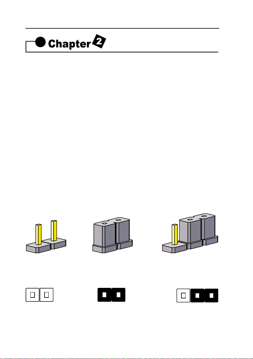
2-1 Setting System Jumpers
You may configure your motherboard to match the needs of your applica-
tions by setting jumpers. A jumper is the simplest kind of electrical switch.
It consists of two metal pins and a small metal clip (often protected by a
plastic cover) that slides over the pins to connect them. To "close" a jumper,
you connect the pins with the clip. To "open" a jumper, you remove the
clip. Sometimes a jumper will have three pins, labeled 1, 2, 3. In this case
you would connect either pin 1 and 2 or 2 and 3.
The jumper settings are schematically depicted in this manual as follows:
A pair of needle-nose pliers may be helpful when working with jumpers.
Installation Procedures
OPEN CLOSED CLOSED 2-3
123

11
8VTAV User’s Manual
Note: When you open the jumper, attach the plastic jumper cap to one of
the pins so you won't lose it.
Warning: Always completely disconnect the power cord from your board
whenever you are working on it. Do not make connections while the power
is on because sensitive electronic components can be damaged by the
sudden rush of power.
Always ground yourself to remove any static charge before touching the
board. Modem electronic devices are very sensitive to static electric
charges. Use a grounding wrist strap at all times. Place all electronic com-
ponents on a static-dissipative surface or in a static-shielded bag when
they are not in the chassis.
Clear CMOS:(JP3)
To clear the data stored in the CMOS, always turn off the computer first,
then remove this jumper to 2-3 pin to clear the CMOS. The jumper should
be set to 1-2 pin (3V battery back up) before turn on the computer.
123
123
DIMM1
DIMM3
DIMM2
LPT1
COM1
COM2
USB
PS/2
ATX POWER
FDC
IDE1
IDE2
FAN2 PCI1
PCI4
PCI3
PCI2
PCI5
AGP4X
IR1
AMR
WOL1
JP3
1
GAME/AUDIO
USB2
ISA1
CD1
CD2
JP7
FAN3
JP1
JP4
SOCKET 462
States JP3
1
2
ClearCMOS
Normal [Default]
* Clear CMOS must be turn off the AC power first.
12
8VTAV User’s Manual
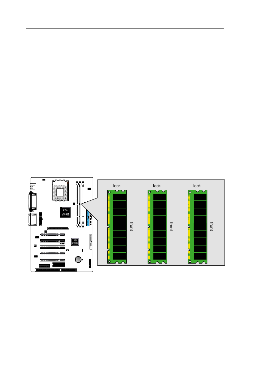
2-2 System Memory (DIMM)
Themotherboard supports up to1.5GB100/133MHzSDRAM. No hardware
or BIOS setup is required after adding or removing the system memory.
Note:
1. The motherboard uses only Dual Inline Memory Modules (DIMMs). Sock-
etsare available for 3.3Volt(powerlevel)Synchronous Dynamic Random
Access Memory (SDRAM).
2. The 100/133 MHz compliant SDRAM must be used because of the strict
timing issues involved under this speed.
Installing system Memory
Insertthe DIMM module(s) as shown. Becausethe numberof pinsare differ-
ent on each side of the breaks, the module will be fitted only in the orienta-
tion shown. The DIMM must be 3.3V for this motherboard.
DIMM1
DIMM3
DIMM2
LPT1
COM1
COM2
USB
PS/2
ATX POWER
FDC
IDE1
IDE2
FAN2 PCI1
PCI4
PCI3
PCI2
PCI5
AGP4X
IR1
AMR
WOL1
JP3
1
GAME/AUDIO
USB2
ISA1
CD1
CD2
JP7
FAN3
JP1
JP4
SOCKET 462

13
8VTAV User’s Manual
2-3 Central Processing Unit (CPU)
The Motherboard provides a ZIF Socket 462. The CPU that came with the
motherboardshouldhave a fan attached to itto preventoverheating. If thisin
not the case, then purchase a fan before you turn on your system. Be sure
that there is sufficient air circulation across the processor heat sink, or the
processor could overheat and damage both the processor and the
motherboard.
Caution: Please choose the suitable heat sink / cooling fan especially
for AMD CPU operating temperature exceeding 700MHz.
Otherwise, the CPU would be totally damaged, resulted from
overheat up to more than 100 degrees in Clesius.
CPU Installation Procedures
1. Thermal tape attach on the center of
the surface.
2.Pull up the ZIF socket CAM to a 90-
degreeangle.

14
8VTAV User’s Manual
3.Locate Pin 1 in the socket,Insert CPU into ZIF socket then pull down the
CAM.
4.Attach FAN/Heatsink assembly onto the CPU.
5.Attach Clip to the socket and connect the power of the FAN.

15
8VTAV User’s Manual
2-4 Expansion Cards
Always unplug the power supply when adding or removing expansion cards
or other system components. Failure to do so may cause severe damage to
both your motherboard and expansion cards.
ExpansionCard Installation Procedure TheMotherboardhas5 PCI , 1AGP,
AMR and 1 ISA expansion slots. You may install up to 5 PCI cards, 1 AGP
and 1 AMR card on this motherboard. To install the PCI cards or AGP card
or AMR card, please follow the following procedure:
1. Read the documentation for your expansion card and make any neces-
sary hardware or software settings for you expansion card, such as
jumpers or switches.
2. Remove your computer system cover and the bracket plate with screw
on the slot you intend to use. Keep the bracket for possible future use.
3. Carefully align the card connectors and press firmly.
4. Secure the card on the slot with the screw you removed above.
5. Replace the computer system cover.
6. Setup the BIOS if necessary.
7. Install the necessary software drivers for your expansion card.
Note: To install the AMR Card. You should set the "AC97 Modem" as "auto"
in the “I"INTEGRATED PERIPHERALS" of the BIOS Setup.
2-5 External Connectors
1.PS/2 Mouse Connector:
The motherboard provides a mini-DIN mouse connector, which supports a
PS/2 style mouse.

16
8VTAV User’s Manual
2.PS/2 Keyboard Connector:
This connector is for a standard keyboard using a PS/2 plug (mini DIN). This
connector will not allow standard AT (large DIN) keyboard plugs. You may
use a DIN to mini DIN adapter on standard AT keyboards. In some
applications, the keyboard is not present, the standard BIOS will report an
error or failure during the Power-On Self Test (POST) after resetting the PC.
You may select "All, But Keyboard" under the "Halt On" in "Standard CMOS
SETUP" of BIOS SETUP.
This allows the system non-keyboard operation without the system halting
during the POST.
3.Universal Serial BUS (USB) Ports 1 & 2:
There are two USB ports on this motherboard for connecting USB devices.
4.Parallel Port Connector:
Normally, the parallel port is used to connect the system to a printer.

17
8VTAV User’s Manual
5.Serial Port COM1 connector:
The COM1 port is ready for a mouse or other serial devices.
6.Serial Port COM2 connector:
The COM2 port is ready for a mouse or other serial devices.
7.Joystick/MIDI connector:
You may connect game joysticks or game pads to this connector for play-
ing games. Connect MIDI devices for playing or editing audio.

18
8VTAV User’s Manual
8.Audio Port connectors:
The Audio Port Connectors on the motherboard are standard1/8"GAME-
AUDIO connectors. Line Out (lime) can be connected to headphones or
POWERED speakers. Line In (light blue) allows tape players or other audio
sources to be recorded by your computer or played through the Line Out
(lime). Mic (pink) allows microphones to be connected for inputting voice.
9.Primary/Secondary IDE Connectors(IDE1 and IDE2)
Themotherboardsupportsup to fourIDEdevices,includingCD-ROM drives,
tape backup drives, Hard Disk Drives, and other IDE devices. After connect-
ing the single end to the board, connect the two plugs at the other end to
your hard disk(s). If you install two hard disks, you must configure the sec-
ond drive to Slave mode by setting its jumper accordingly. Please refer to
your hard disk documentation for the jumper settings. (Pin 20 is removed to
prevent the users inserting the IDE devices in the wrong orientation when
using ribbon cables with pin 20 plugged).
Note: Ultra DMA/66 IDE devices must use an 80-wire IDE cable or else
devices will automatically be limited to Ultra DMA/33 mode.
AUDIOOUT AUDIOIN MICROPHONEIN
PC99 Color: Lime PC99 Color:Light Blue PC99 Color: Pink
DIMM1
DIMM3
DIMM2
LPT1
COM1
COM2
USB
PS/2
ATX POWER
FDC
IDE1
IDE2
FAN2 PCI1
PCI4
PCI3
PCI2
PCI5
AGP4X
IR1
AMR
WOL1
JP3
1
GAME/AUDIO
USB2
ISA1
CD1
CD2
JP7
FAN3
JP1
JP4
SOCKET 462
Primary/Secondary IDE Connectors
Primary IDE
Connectors
Color:Blue
Secondary
IDE Connec-
tors
Color:White
Note:orient the red markings on the floppy
ribbon cable to pin1

19
8VTAV User’s Manual
10.Floppy Disk Drive Connector(FDC)
You can attach up to two floppy drives to the motherboard. After connecting
the single end to the board, connect the two plugs on the other end to the
floppy drives. The drive A: should be connected on the end and the drive B:
in the middle.
Note: Pin 5 is removed to prevent the users inserting the Floppy Disk Drive
in the wrong orientation when using ribbon cables with pin 5 plugged.
11.Wake-On-LAN(WOL)/Wake-On-Modem(WOM) connectors(WOL1)
The Wake-On-LAN and Wake-On-Modem connectors connect to a LAN
card and Modem card respectively with a Wake-On-LAN/Wake-On-Modem
output. The connectors power up the system when a wakeup packet or
signal is received through the LAN card/Modem card.
DIMM1
DIMM3
DIMM2
LPT1
COM1
COM2
USB
PS/2
ATX POWER
FDC
IDE1
IDE2
FAN2 PCI1
PCI4
PCI3
PCI2
PCI5
AGP4X
IR1
AMR
WOL1
JP3
1
GAME/AUDIO
USB2
ISA1
CD1
CD2
JP7
FAN3
JP1
JP4
SOCKET 462
PIN
FUNCTION
Wake-On-Lan(WOL)connectors
NOTE:TheATXpowersupplysupportslarger
than 720mA 5V Standby current
DIMM1
DIMM3
DIMM2
LPT1
COM1
COM2
USB
PS/2
ATX POWER
FDC
IDE1
IDE2
FAN2 PCI1
PCI4
PCI3
PCI2
PCI5
AGP4X
IR1
AMR
WOL1
JP3
1
GAME/AUDIO
USB2
ISA1
CD1
CD2
JP7
FAN3
JP1
JP4
SOCKET 462
Floppy Disk Drive
Connector
Color: White
Note: Orient the red marking on the floppy
ribbon cable to pin1

20
8VTAV User’s Manual
12.Universal Serial BUS (USB) PIN Header(USB2)
There are two USB PIN Header on this motherboard for connecting USB
devices.
Caution: Pls. Compare each pin assignment of USB cable with that of USB
PIN header listed above. If both are not matched, please contact your dis-
tributor for suitable cable. Otherwise, we will not be able to responsible for
any problem arised from this issue.
13.CPU/AGP Fan Connectors(FAN1 and FAN2)
This motherboard provides CPU, Power, and Chassis fan connectors. Ori-
entatethe fan so that the heatsink fins allowairflow togo across theonboard
heat sink(s) instead of the expansion slots. Depending on the fan
manufacturer, the wiring and plug may be different. The red wire should be
positive, while the black should be ground. Connect the fan plug to the board
taking into consideration the polarity of the connector.
DIMM1
DIMM3
DIMM2
LPT1
COM1
COM2
USB
PS/2
ATX POWER
FDC
IDE1
IDE2
FAN2 PCI1
PCI4
PCI3
PCI2
PCI5
AGP4X
IR1
AMR
WOL1
JP3
1
GAME/AUDIO
USB2
ISA1
CD1
CD2
JP7
FAN3
JP1
JP4
SOCKET 462
Universal Serial BUS (USB) PIN Header
PIN
FUNCTION
FUNCTION
PIN
DIMM1
DIMM3
DIMM2
LPT1
COM1
COM2
USB
PS/2
ATX POWER
FDC
IDE1
IDE2
FAN 2 PCI1
PCI4
PCI3
PCI2
PCI5
AGP4X
IR1
AMR
WOL1
JP3
1
GAME/AUDIO
USB2
ISA1
CD1
CD2
JP7
FAN 3
JP1
JP4
SOCKET 462
1
SENSOR
2+12
3
GND
1
2
3SENSOR
+12
GND
CPU Fan Connectors
AGP Fan Connectors
Table of contents
Other Fastfame Motherboard manuals


