Fastfame 9W AP Series User manual

Copyright 2000 Publishing. All Rights Reserved.
This manual, software and firmware described in it are copyrighted by
their respective owners and protected under the laws of the Universal
Copyright Convention. You may not reproduce, transmit, transcribe,
store in a retrieval system, or translate into any language, in any form or
by any means, electronic, mechanical, magnetic, optical, chemical,
biological, molecular, manual, or otherwise, any part of this publication
without the express written permission of the publisher.
All products and trade names described within are mentioned for
identification purpose only. No affiliation with or endorsement of the
manufacturer is made or implied. Product names and brands appearing
in this manual are registered trademarks of their respective companies.
The information published herein has been checked for accuracy as of
publishing time. No representation or warranties regarding the fitness
of this document for any use are made or implied by the publisher. We
reserve the right to revise this document or make changes in the
specifications of the product described therein at any time without
notice and without obligation to notify any person of such revision or
change.
Print in Taiwan.
User Manual V1.1
9W_AP/P+
9W_AP/P+

Item Checklist
Before you begin installing your motherboard, please make
sure that the following materials have been shipped:
If you discover damaged or missing items, please contact
your retailer.
This mainboard comes in a sturdy cardboard shipping
carton, which should contain the following items:
• This Mainboard
• This User’s Manual
• CD Title Driver
• Cable Set
User’s manual Version : 1.10
Release Date : Feb. 2000

9W
▄
AP/P +Serial User’s Manual
CONTENTS
1Introduction
1-1Introduction …………………………………………………………1-1
1-2Specifications ……………………………………………………….1-1
1-3PACKAGE CHECKLIST ………………………………………….1-3
1-4Block Diagram ……………………………………………………1-4
1-5Main Board Layout with Default Setting ……………………….1-5
1-6Static Electricity Precautions …………………………………… 1-6
2Installation Procedures
2-1Setting System Jumpers …………………………………………2-1
2-2System Memory (DIMM) …………………………………………2-4
2-3Central Processing Unit (CPU) …………………………………2-6
2-4Expansion Cards ………………………………………………….2-6
2-5External Connectors ………………………………………………2-7
2-6Power Connection Procedures ………………………………...2-17
3AWARD BIOS Setup
3-1Introduction…………………………………………………………3-1
3-2Main Menu …………………………………………………………3-4
3-3Standard CMOS Setup ……………………………………………3-6
3-4Advanced BIOS Features ………………………………………3-10
3-5Advanced Chipset Features/Integrated Peripherals …………3-13
3-6Integrated Peripherals …………………………………………..3-16
3-7Power Management Setup…………………………………….. 3-21
3-8PnP/PCI Configuration Setup ………………………………….3-25
3-9PC Health Status ………………………………………………...3-27
3-10 Frequency/Voltage Control ……………………………………3-28
3-11 Defaults Menu ………………………………………………….3-29
3-12 Supervisor/User Password Setting ………………………….. 3-30
3-13 Exit Selecting ……………………………………………………3-31
4Software Driver Install
4-1UPDATEDPRODUCT INFORMATION………………………... 4-1
4-2Install Graphics Driver …………………………………………… 4-4
4-3Install Audio Driver ………………………………………………..4-7
5Anti-Virus software installation
5-1Anti-Virus software installation ………………………………….. 5-1
9W
▄
AP/P +Serial User’s Manual
1-1
Introduction
1-1 Introduction
The motherboard is a high-performance, low-cost motherboard which supports the
Intel PII;PIII and Socket 370 microprocessor.System memory bank supports 3
DIMM socket. Memory up to 512MB PC-100 SDRAM.
On-board features include 2X AGP, stereo sound, ATX power, super I/O, 2 Ultra
DMA/66 EIDE interfaces, 2 USB ports, 5PCI expansion slots, and 1 AMR slot
1 Fastfame default Slot for OPCA and DPSA card.
1-2 Specifications
CPU
-Pentium ® II/III®/Celeron TM Processor.
-Celeron TM Socket 370 PPGA packaged Processor.
-2 nd level Cache Depend on CPU.
-Coppermine Socket 370 FCPGA packaged Processor.
Chipset -Intel®GMCH82810/810DC100/810E,consisting of:
-82810DC100/82810E Graphics and memory controller
Hub(GMCH).
-82801AA(ICH) I/O Controller Hub.
Clock Generator
-Supports 66 / 100 / 133MHz.
Memory
-3 x 168-pin DIMM Sockets.
-Supports PC-100 SDRAM 16MB~512MB.
-Supports only 3.3V SDRAM DIMM.
VGA -Integrated 2D/3D graphics chip(GMCH).
-Integrated 24-bit 230MHz RAMDAC.
-4MB display cache.(9WEAP/P+ Without)
-Integrated H/W Motion compensation engine.
9W
▄
AP/P +Serial User’s Manual
1-2
Audio -On board ALS300+ Sound Chip.
-Supports Dual AC-97 CODEC/Up to 6-Channel
Speakers.
-QSound QEMTM(Creative EAXTM compatible) Support.
-Built-in ALS FM synthesizer.
-Enhanced normal & digital game port.
-Supports AC97 CODEC (ALC100).
-Supports earphones, two channel speaker mode.
-MPU-401 game/MIDI port and Sound blaster®16
compatible.
I/O Control -ITE IT8712F.
Expansion Slot -Five 32-bit PCI slots support Master mode.
-One AC3 & TV OUT Slot.
-One Audio Modem Riser (AMR) slot.
I/O Interface -PCI Bus master IDE interface on board with two
connectors support 4 IDE devices in 2 channel, the PCI
IDE Controller supports PIO Mode 0 to Mode 4, Bus
master IDE DMA Mode 2 and Ultra DMA 33/66.
-On board super Multi-I/O chip that support 2 serial port
with 16550 Fast UART compatible, 1 parallel port with
EPP and ECP capabilities, and a floppy disk drive
interface.
-On board support PS/2 mouse Connector.
-On board support PS/2 Keyboard Connector.
-On board 2 USB ports.
-On board IrDA connector.
-Floppy port supports 2 FDD with 360K, 720K,1.2M,1.44M
and 2.88M bytes ,Supports LS-120 floppy disk device.
Other Function -Support Modem Ring Power On.
-Supports Keyboard, PS/2 Mouse power on, and
WOL (Wake On LAN).
Power Supply -On board 3V, 5V and 12V 20-pin ATX power connector.
9W
▄
AP/P +Serial User’s Manual
1-3
-Use switching regulator to support CPU core voltage.
Hardware Monitor
-CPU/Power Supply/Chassis Fan Revolution detecting.
-CPU Fan Control.
-System Voltage Detect.
-Display Actual Current Voltage.
BIOS -Licensed AWARD BIOS, 4M bit FLASH RAM.
-ACPI ready for PC98/Windows 98.
-System BIOS supports ACPI function and Green feature
function, DMI, Plug and Play Flash ROM.
Form factor -ATX Form Factor.
-Dimensions 305mm x 190mm, 4 layers PCB.
TV OUT& LCD Monitor(Use OPCA CARD or DPSA CARD Only)
-On card CHRONTEL CH7007/7008 digital PC to TV
encoder.
-Supports NTSC, and PAL TV formats.
-Provides Composite, S-Video outputs.
-Auto-detection of TV presence.
-Support AC-LINK DFP Interface LCD Monitor.
DRIVERS -Intel®810 Chipset Graphics Drivers.
-Intel®INF Installation Utility.
-AC97 audio sound drivers and Applications..
-Avance Logic AL300+ driver and Applications.
-DirectX 6.1.
1-3PACKAGE CHECKLIST
If you discover any item below was damaged or lost, please contact your vendor.
◇The main board.
◇One OPCA or DPSA Card (Option).
◇This user manual.
◇One Floppy disk drive cable.
◇One Ultra DMA/66 IDE cable.
◇One External COMB cable. [TYPE B]
9W
▄
AP/P +Serial User’s Manual
1-4
◇Software utilities.
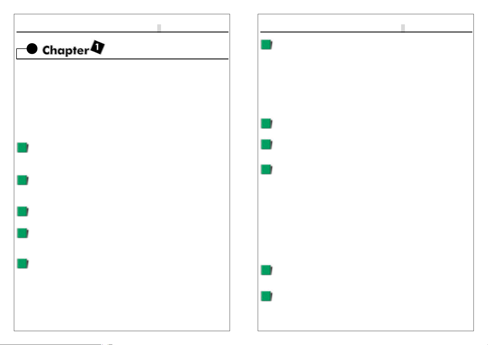
1-4Block Diagram
I/O
IT8712F

9W
▄
AP/P +Serial User’s Manual
1-5
1-5 Main Board Layout with Default Setting
9W
▄
AP/P +Serial User’s Manual
1-6
1-6Static Electricity Precautions
Static electricity can easily damage your motherboard.
Observing a few basic precautions can help you safeguard against damage that
could result in expensive repairs. Follow the measures below to protect your
equipment from static discharge:
Keep the motherboard and other system components in their antistatic
packaging until you are ready to install them.
Touch a grounded surface before you remove any system component from
its protective antistatic packaging. A grounded surface within easy reach is
the expansion slot covers at the rear of the system case. or any other
unpainted portion of the system chassis.
During configuration and installation, touch a ground surface frequently to
discharge any static electric charge that may build up in your body. Another
option is to wear a grounding wrist strap.
When handling a motherboard or an adapter card, avoid touching its
components. Handle the motherboard and adapter cards either by the
edges or by the mounting bracket that attaches to the slot opening in the
case.

9W
▄
AP/P +Serial User’s Manual
1-7

9W
▄
AP/P +Serial User’s Manual
2-1
Installation Procedures
The mainboard has some user-adjustable jumpers on the board that allow you to
configure your system to suit your requirements. This chapter contains information
on the various jumper settings on your mainboard.
To set up your computer, you must complete the following steps:
1. Setting system jumpers.
2. Install RAM modules.
3. Install CPU & FAN.
4. Connect ribbon cables, cabinet wires, and power supply.
5. Set up BIOS.
6. Set up system drivers and utility.
2-1Setting System Jumpers
You may configure your motherboard to match the needs of your applications by
setting jumpers. A jumper is the simplest kind of electrical switch. It consists of two
metal pins and a small metal clip (often protected by a plastic cover) that slides
over the pins to connect them. To “close” a jumper, you connect the pins with the
clip. To ”open” a jumper, you remove the clip. Sometimes a jumper will have three
pins, labeled 1, 2, 3. In this case you would connect either pin 1 and 2 or 2 and 3.
OPEN CLOSED CLOSED 2-3
9W
▄
AP/P +Serial User’s Manual
2-2
The jumper settings are schematically depicted in this manual as follows:
A pair of needle-nose pliers may be helpful when working with jumpers.
Note: When you open the jumper, attach the plastic jumper cap to one of the pins
so you won’t lose it.
Warning: Always completely disconnect the power cord from your board
whenever you are working on it. Do not make connections while the power is on
because sensitive electronic components can be damaged by the sudden rush of
power.
Always ground yourself to remove any static charge before touching the board.
Modem electronic devices are very sensitive to static electric charges. Use a
grounding wrist strap at all times. Place all electronic components on a
static-dissipative surface or in a static-shielded bag when they are not in the
chassis.
CPU External Frequency Settings:(JP5A,JP5B)
The Motherboard supports Intel Socket 370 CPUs with 66MHz or 100MHz or
133MHz(9WEAP/P+ series only) external frequency. Setting the jumper according
to the external frequency of the CPU you are going to install on the motherboard.
states JP5A JP5B
1BIOS auto-detect CPU
Frequency(66/100MHZ)
2
Over clock
100MHz (Celeron only)
We don’t recommand
you to setup.
3BIOS auto-detect CPU
Frequency(100/133MHz)
*9WAP/P+ & 9WDAP/P+ [JP5A] always close [default].
*JP5A for Pentium® III 133MHz Front bus only.

9W
▄
AP/P +Serial User’s Manual
2-3
Clear CMOS:(JP6)
To clear the data stored in the CMOS, always turn off the computer first, then
remove this jumper to 2-3 pin to clear the CMOS. The jumper should be set to 1-2
pin (3V battery back up) before turn on the computer.
Keyboard Power On Selection
The keyboard power on selection function. If your ATX power supply can supports
700mA 5V standby current (with keyboard require).you can use this function.
states JP6
1Clear CMOS
2Normal [Default]
* Clear CMOS must be turn off the AC power first.
states JP1
1Enable this function
2Disable [Default]
*If your ATX power supply not support 700mA 5V
standby current. Don’t enable this function.
9W
▄
AP/P +Serial User’s Manual
2-4
On Board Sound Chip ALS300+ Selection
The Sound chip selection function. If your don’t like this sound system you can
Disable On board sound.
2-2System Memory (DIMM)
The motherboard supports up to 512MB PC-100 SDRAM. No hardware or BIOS
setup is required after adding or removing the system memory.
The Intel 810 chipset does not support ECC, However, ECC memory modules
may still be used, but the ECC function will not be available.
Note:
1.The motherboard uses only Dual Inline Memory Modules (DIMMs). Sockets are
available for 3.3Volt (power level) Synchronous Dynamic Random
Access Memory (SDRAM).
2.This motherboard does not support 66MHz SDRAM !.The PC-100 compliant
SDRAM must be used because of the strict timing issues involved under this
speed.
states JP7
1Disable this function
2Enable this function
[Default]

9W
▄
AP/P +Serial User’s Manual
2-5
Installing system Memory
Insert the DIMM module(s) as shown. Because the number of pins are different on
each side of the breaks, the module will be fitted only in the orientation shown.
The DIMM must be 3.3V for this motherboard.
System memory blank table
Item Support Support
DIMM 1 Single side Double side
DIMM 2 Single side Double side
DIMM 3 Single side
* DIMM 3 support Single side SDRAM module only.
Ex.
ITEM DIMM 1 DIMM 2 DIMM 3 TOTAL SIZE
132MB-Single 32MB-Single 32MB-Single 96MB
232MB-Double 32MB-Single 32MB-Single 96MB
332MB-Double 32MB-Double Don’t use 96MB
464MB-Single 64MB-Single 64MB-Single 192MB
564MB-Double 64MB-Single 64MB-Single 192MB
664MB-Double 64MB-Double Don’t use 128MB
7128MB-Single 128MB-Single 128MB-Single 384MB
8128MB-Double 128MB-Single 128MB-Single 384MB
9128MB-Double 128MB-Double Don’t use 256MB
10 256MB-Single 256MB-Single Don’t use 512MB
11 256MB-Double 256MB-Single Don’t use 512MB
12 256MB-Double 256MB-Double Don’t use 512MB
9W
▄
AP/P +Serial User’s Manual
2-6
2-3 Central Processing Unit (CPU)
The Motherboard provides a ZIF Socket 370 and a SLOT 1. The CPU that came
with the motherboard should have a fan attached to it to prevent overheating. If
this in not the case, then purchase a fan before you turn on your system. Be sure
that there is sufficient air circulation across the processor heat sink, or the
processor could overheat and damage both the processor and the motherboard.
To install a CPU, first turn off your system and remove its cover. Locate the ZIF
socket and open it by first pulling the lever sideways away from the socket then
upwards to a 90-degree angle. Insert the CPU with the correct orientation as
shown. The notched corner should point towards the end of the lever. Because
the CPU has a corner pin for two of the four corners, the CPU will only be fitted in
the orientation as shown. The picture is for reference only: you should have a
CPU fan that covers the top side of the CPU. With the added weight of the CPU
fan, no force is required to insert the CPU. Once completely inserted, close the
socket lever while holding down the CPU.
2-4Expansion Cards
Always unplug the power supply when adding or removing expansion cards or
other system components. Failure to do so may cause severe damage to both
your motherboard and expansion cards.
Expansion Card Installation Procedure The Motherboard has 3 PCI and 1 AMR
expansion slots. You may install up to 3 PCI cards and 1 AMR card on this
motherboard. To install the PCI cards or AMR card, please follow the following
procedure:
1.Read the documentation for your expansion card and make any necessary
hardware or software settings for you expansion card, such as jumpers or
switches.
2.Remove your computer system cover and the bracket plate with screw on the
slot you intend to use. Keep the bracket for possible future use.
3.Carefully align the card connectors and press firmly.
4.Secure the card on the slot with the screw you removed above.
5.Replace the computer system cover.
6.Setup the BIOS if necessary.
7.Install the necessary software drivers for your expansion card.
Note: To install the AMR Card. You should set the “AC97 Modem” as ”auto” in the
”INTEGRATED PERIPHERALS” of the BIOS Setup.
9W
▄
AP/P +Serial User’s Manual
2-7
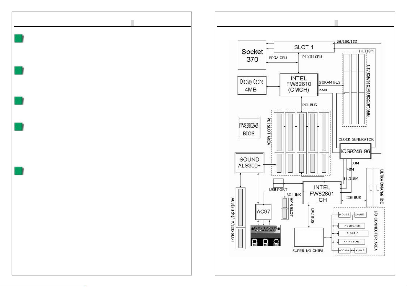
2-5 External Connectors
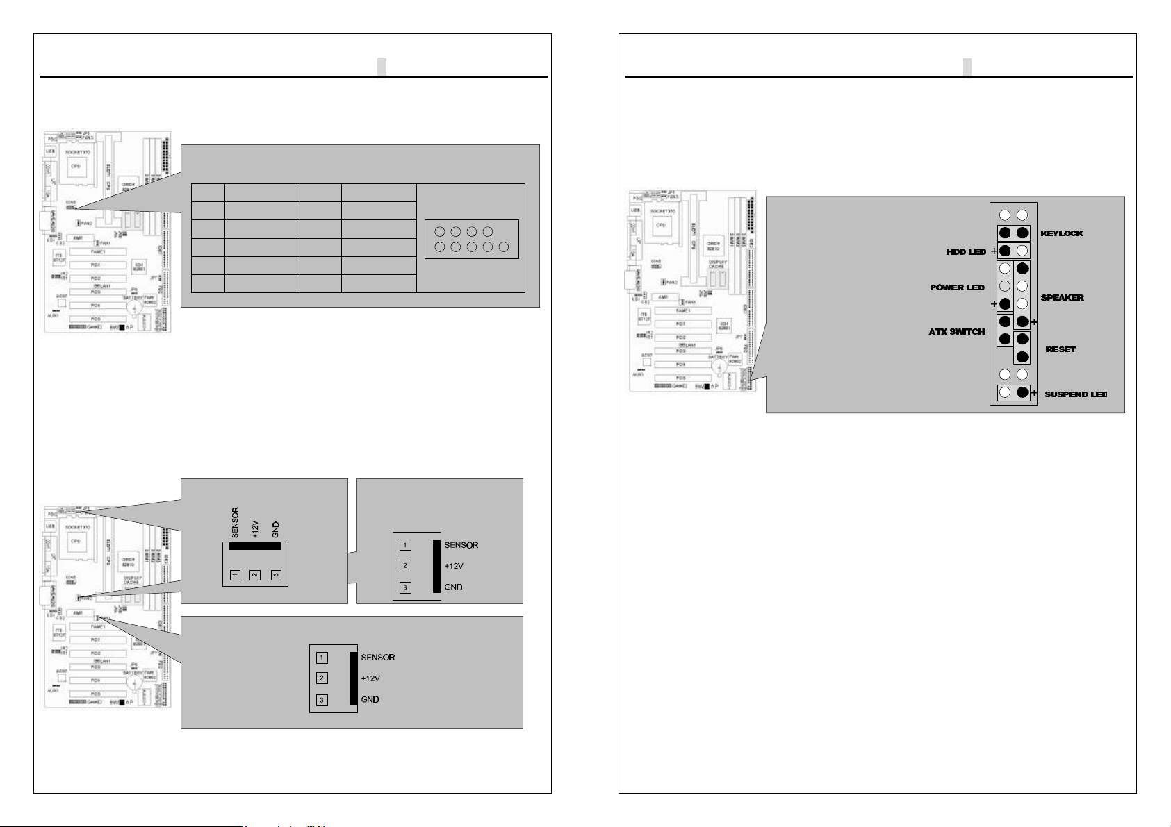
1.PS/2 Mouse Connector:
The motherboard provides a mini-DIN mouse connector, which supports a PS/2
style mouse.
SLOT Area
AMR
PCI SLOT
PS/2 Mouse Connector
PC99 Color : Green
PIN FUNCTION
1DATA
2,6 N.C
3GND
4+5V
5CLOCK
FAME SLOT
9W
▄
AP/P +Serial User’s Manual
2-8
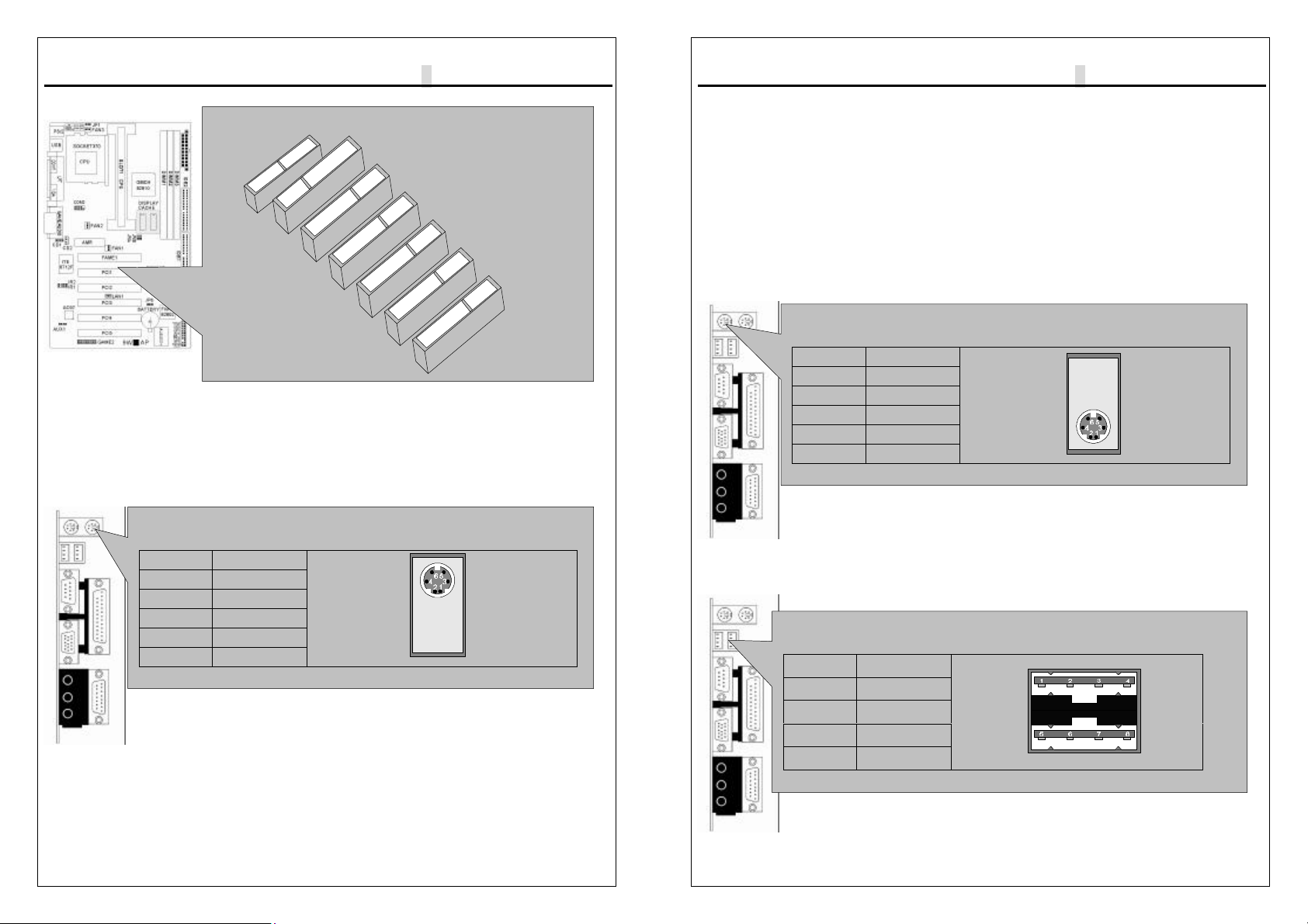
2.PS/2 Keyboard Connector:
This connector is for a standard keyboard using a PS/2 plug (mini DIN). This
connector will not allow standard AT (large DIN) keyboard plugs. You may
use a DIN to mini DIN adapter on standard AT keyboards. In some applications,
the
keyboard is not present, the standard BIOS will report an error or failure during the
Power-On Self Test (POST) after resetting the PC. You may select “All, But
Keyboard” under the ”Halt On” in “Standard CMOS SETUP” of BIOS SETUP.
This allows the system non-keyboard operation without the system halting during
the POST.
3.Universal Serial BUS (USB) Ports 1 & 2:
There are two USB ports on this motherboard for connecting USB devices.
PS/2 Keyboard Connector
PC99 Color : Purple
PIN FUNCTION
1DATA
2,6 N.C
3GND
4+5V
5CLOCK
Universal Serial BUS (USB) Ports 1 & 2
PC99 Color : Black
PIN FUNCTION
1,5 +5V
2,6 USB+
3,7 USB-
4,8 GND
9W
▄
AP/P +Serial User’s Manual
2-9
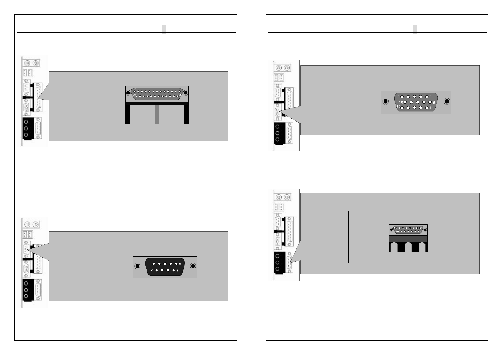
4.Parallel Port Connector:
Normally, the parallel port is used to connect the system to a printer.
5.Serial Port COM1 connector:
The COM1 port is ready for a mouse or other serial devices. A second serial port
is available using a serial port bracket connected from the motherboard to an
expansion slot opening.
Parallel Port Connector
PC99 Color : Burgundy
Serial Port COM1 connector
PC99 Color : Turquoise
9W
▄
AP/P +Serial User’s Manual
2-10
6.Display connector:
This connector is for output to a VGA-compatible device, commonly used for
conventional CRT displays.
7.Joystick/MIDI connector:
You may connect game joysticks or game pads to thisconnector for playing
games. Connect MIDI devices for playing or editing audio.
Display connector
PC99 Color : Blue
Joystick/MIDI connector
JOYSTICK
PORT
PC99 Color:
Gold

9W
▄
AP/P +Serial User’s Manual
2-11
8.Audio Port connectors:
The Audio Port Connectors on the motherboard are standard1/8”GAME-AUDIO
connectors. Line Out (lime) can be connected to headphones or POWERED
speakers. Line In (light blue) allows tape players or other audio sources to be
recorded by your computer or played through the Line Out (lime). Mic (pink)
allows microphones to be connected for inputting voice.
9.Primary/Secondary IDE Connectors
The motherboard supports up to four IDE devices, including CD-ROM drives, tape
backup drives, Hard Disk Drives, and other IDE devices. After connecting
the single end to the board, connect the two plugs at the other end to your hard
disk(s). If you install two hard disks, you must configure the second drive to
Slave mode by setting its jumper accordingly. Please refer to your hard disk
documentation for the jumper settings. (Pin 20 is removed to prevent the users
inserting the IDE devices in the wrong orientation when using ribbon cables with
pin 20 plugged).
Audio Port connectors
MICROPHONE IN AUDIO
IN AUDIO
OUT
PC99 Color :
Pink PC99 Color : Light
Blue PC99 Color : Lime
Primary/Secondary IDE Connectors
Primary IDE Connectors
Color : Blue Secondary IDE Connectors
Color : White
PIN1
PIN1
NOTE: Orient the red markings on the floppy ribbon cable to
pin 1
9W
▄
AP/P +Serial User’s Manual
2-12
Note: Ultra DMA/66 IDE devices must use an 80-wire IDE cable or else devices
will automatically be limited to Ultra DMA/33 mode.
10.Floppy Disk Drive Connector:
You can attach up to two floppy drives to the motherboard. After connecting the
single end to the board, connect the two plugs on the other end to the floppy
drives. The drive A: should be connected on the end and the drive B: in the
middle.
Note: Pin 5 is removed to prevent the users inserting the Floppy Disk Drive in the
wrong orientation when using ribbon cables with pin 5 plugged.
11.Wake-On-LAN(WOL)/Wake-On-Modem(WOM) connectors
The Wake-On-LAN and Wake-On-Modem connectorsconnect to a LAN card and
Modem card respectively with a Wake-On-LAN/Wake-On-Modem output.
The connectors power up the system when a wakeup packet or signal is received
through the LAN card/Modem card.
Floppy Disk Drive Connector
Floppy Disk Drive Connector Color : White
NOTE: PIN1
Orient the red markings on the floppy ribbon cable to pin 1
Wake-On-LAN(WOL) connectors
PIN FUNCTION
1+5V_SB
2GND
3SIGNAL
NOTE : The ATX power supply supports larger than 720mA
5V Standby current.
9W
▄
AP/P +Serial User’s Manual
2-13
12.Serial Port COM2 Pin Header:
The provided serial port bracket can be used to add an additional serial port for
additional serial devices.
Note: Pin 10 is removed to prevent the users inserting in the wrong orientation
when using ribbon cables with pin 10 plugged.
13.CPU/Chassis Fan Connectors:
This motherboard provides CPU, Power, and Chassis fan connectors. Orientate
the fan so that the heat sink fins allow airflow to go across the onboard heat sink(s)
instead of the expansion slots. Depending on the fan manufacturer, the wiring and
plug may be different. The red wire should be positive, while the black should be
ground. Connect the fan plug to the board taking into consideration the polarity of
the connector.
Serial Port COM2 Pin Header
B TYPE
PIN FUNCTION PIN FUNCTION
1DCD 6DSR
2RXD 7RTS
3TXD 8CTS
4DTR 9RI
5GND 10 N.C
CPU Fan Connectors
CPU Fan Connectors
ChassisFan Connectors
9W
▄
AP/P +Serial User’s Manual
2-14
Note: The CPU and motherboard will overheat if there is noairflow across the
CPU and onboard heatsink. Damage may occur to the motherboard and the CPU
fan if these pins are incorrectly used. These are not jumpers, do not place jumper
caps over these pins.
SystemPanelConnectors
Refer to the following figure for item 14 to 18.
14.Power LED Lead
This indicates the status of the system power is turned”ON’ or ”OFF”The LED will
light when the system power is turned on and will go off when the system power is
turned off.
15.System Warning Speaker Connector
This 4-pin connector connects to the case-mounted speaker.
16.ATX Power Switch Lead
The system power is controlled by a momentary switch connected to this lead.
Pressing the button once will switch the system between ON and SOFT OFF.
Pushing the switch while in the ON mode for more than 4 seconds will turn the
system off. The Power LED shows the status of the system power.
17.HDD LED Lead
This connector supplies power to the cabinet IDE activity LED. Read and write
activity by devices connected to the Primary or Secondary IDE connectors will
cause the LED to Light up.
18.Reset Switch Lead
This 2-pin connector connects to the case-mounted reset switch for rebooting your
computer without having to turn off your power switch. This is a preferred method
of rebooting to extend the life of the system power supply.
SystemPanelConnectors
Correction Page
9W
▄
AP/P +Serial User’s Manual
2-15
19. Internal Audio Connectors:
These connectors allow you to receive stereo audio input from the sound sources
such as CD-ROM, TV tuner, and MPEG card.
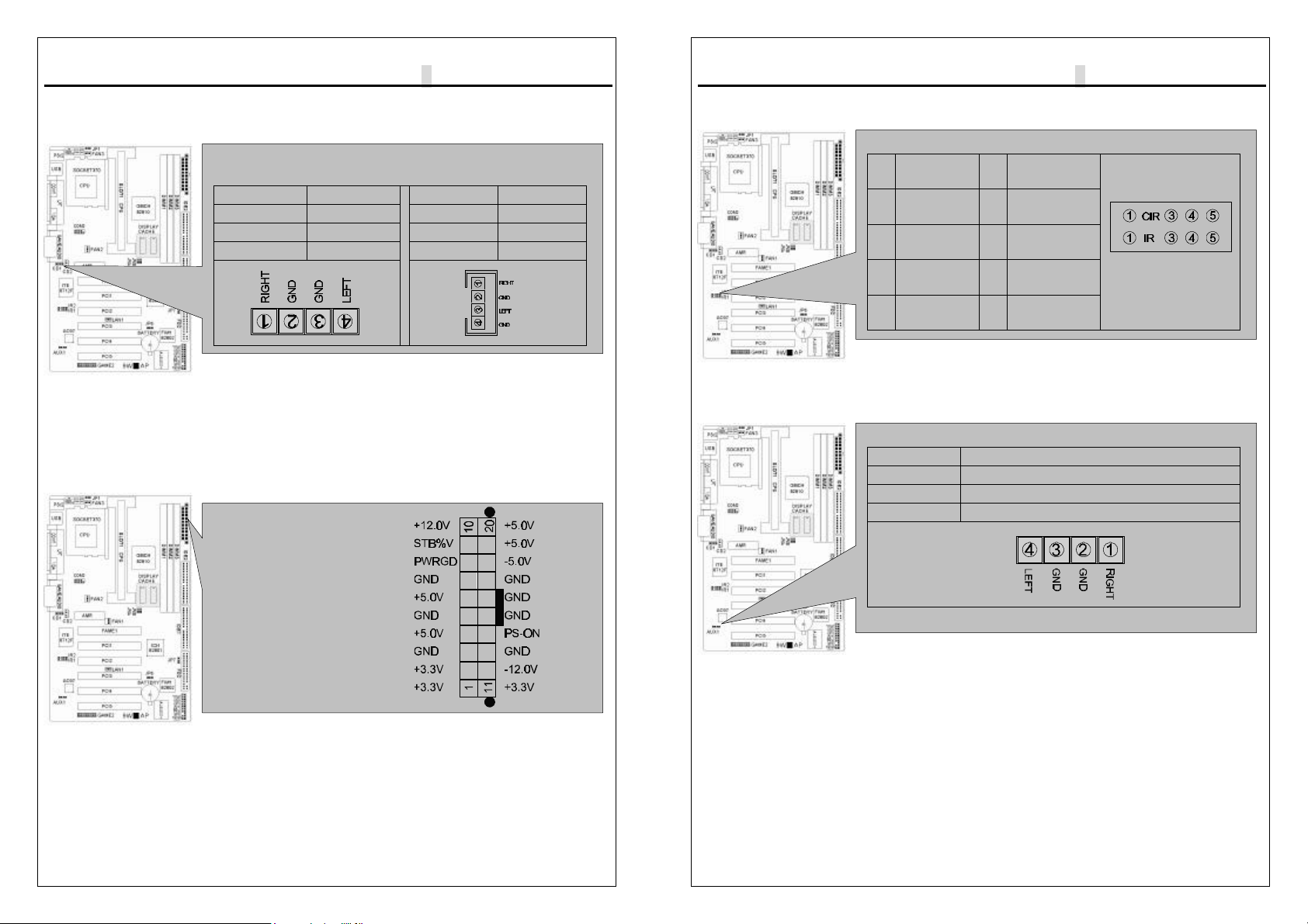
20.ATX Power Connector:
This connector connects to an ATX power supply. The plug from the power supply
will only insert in one orientation because of the different hole sizes. Find the
proper orientation and push down firmly making sure that the pins are aligned.
Internal Audio Connectors
CD1 CD2
PIN FUNCTION PIN FUNCTION
1RIGHT 1RIGHT
2,4 GND 2,3 GND
3LEFT 4LEFT
ATX Power Connector
9W
▄
AP/P +Serial User’s Manual
2-16
21.IR&CIR Pin Header:
22.AUXIN1 Pin Header:
2-6Power Connection Procedures
IR&CIR Pin Header
PIN
IR PIN
CIR
1+5 VCC 1+5 VCC
3IRRX 3CIRRX
4GND 4GND
5IRTX 5CIRRTX
AUXIN1
PIN FUNCTION
1RIGHT
2,4 GND
3LEFT

9W
▄
AP/P +Serial User’s Manual
2-17
After all connections are made, close the system case cover.
Be sure that all switches are OFF.
Connect the power supply cord to the power supply located on the back of
your system case according to your system user manual.
Connect the power cord to a power outlet that is equipped with a surge
protector.
You may then turn ON your devices in the following order:
(1) Your monitor
(2) External SCSI devices (starting with the last device on the chain)
(3) Your system power For ATX power supplies, you need to switch ON the
power supply if a switch is provided as well as press the ATX power
switch on the front of the case.
The power LED on the front panel of the system case will light. For ATX
power supplies, the power LED will light when the ATX power switch is
pressed. The system will then run power-On tests. While the tests are
running, additional messages will appear on the screen. If you do not see
anything within 30 seconds from the time you turn on the power, the system
may have failed a power-on test. Check your jumper settings and
connections again or call your retailer for assistance.
During power-ON, hold down <Delete> to enter BIOS setup.
Follow the instructions in chapter 3 BIOS Setup
To power off you computer, you must first exit or shut down your operating
system before switching OFF the power switch. For ATX power supplies,
you can press the ATX power switch after exiting or shutting down your
operating system. If you use Windows 95/98, click the start button,
click shut down, and then click Shut down the computer. The power supply
should turn OFF after Windows shuts down. For ATX power supplies, the
message ”You can now safely turn OFF your computer” will not appear
when shutting down the computer.
9W
▄
AP/P +Serial User’s Manual
3-1
AWARD BIOS Setup
3-1 Introduction
This manual discusses Award™ Setup program built into the ROM BIOS. The
Setup program allows users to modify the basic system configuration. This
special information is then stored in battery-backed RAM so that it retains the
Setup information when the power is turned off.
The AwardBIOS™ installed in your computer system’s ROM (Read Only Memory)
is a custom version of an industry standard BIOS. This means that it supports
Intel/Cyrix/AMD processors in a standard IBM-AT compatible input/output system.
The BIOS provides critical low-level support for standard devices such as disk
drives and serial and parallel ports.
The AwardBIOS™ has been customized by adding important, but non-standard,
features such as virus and password protection as well as special support for
detailed fine-tuning of the chipset controlling the entire system.
The rest of this manual is intended to guide you through the process of configuring
your system using Setup.
Starting Setup
The AwardBIOS™ is immediately activated when you first power on the computer.
The BIOS reads the system information contained in the CMOS and begins the
process of checking out the system and configuring it. When it finishes, the
BIOS will seek an operating system on one of the disks and then launch and turn
control over to the operating system.
While the BIOS is in control, the Setup program can be activated in one of two
ways:
1. By pressing <Del> immediately after switching the system on, or
2. By pressing the <Del> key when the following message appears briefly at the
bottom of the screen during the POST (Power On Self-Test).
Press DEL to enter SETUP.
If the message disappears before you respond and you still wish to enter Setup,
restart the system to try again by turning it OFF then ON or pressing the "RESET"
button on the system case. You may also restart by simultaneously pressing
<Ctrl>, <Alt>, and <Delete> keys. If you do not press the keys at the correct
time and the system does not boot, an error message will be displayed and you
will again be asked to...
9W
▄
AP/P +Serial User’s Manual
3-2
PRESS F1 TO CONTINUE, DEL TO ENTER SETUP
Using Setup
In general, you use the arrow keys to highlight items, press <Enter> to select, use
the PageUp and PageDown keys to change entries, press <F1> for help and
press <Esc> to quit. The following table provides more detail about how to
navigate in the Setup program using the keyboard.
Key Function
Up Arrow Move to the previous item
Down Arrow Move to the next item
Left Arrow Move to the item on the left (menu bar)
Right Arrow Move to the item on the right (menu bar)
Esc Main Menu: Quit without saving changes
Submenus: Exit Current page to the next higher level menu
Move Enter Move to the item you desired
PgUp key Increase the numeric value or make changes
PgDn key Decrease the numeric value or make changes
+ key Increase the numeric value or make changes
-key Decrease the numeric value or make changes
Esc key Main Menu -- Quit and not save changes into CMOS
Status Page Setup Menu and Option Page Setup Menu -- Exit
current page and return to Main Menu
F1 key General help on Setup navigation keys
F5 key Load previous values from CMOS
F6 key Load the fail-safe defaults from BIOS default table
F7 key Load the optimized defaults
F10 key Save all the CMOS changes and exit
Navigating through the menu bar
Use the left and right arrow keys to choose the menu you want to be in.
To display a sub menu, use the arrow keys to move the cursor to the sub menu
you want. Then press <Enter>. A “Ø” pointer marks all sub menus.
Getting Help
Press F1 to pop up a small help window that describes the appropriate keys to
use and the possible selections for the highlighted item. To exit the Help Window
press <Esc> or the F1 key again.
9W
▄
AP/P +Serial User’s Manual
3-3
In Case of Problems
If, after making and saving system changes with Setup, you discover that your
computer no longer is able to boot, the AwardBIOS™ supports an override to the
CMOS settings which resets your system to its defaults.
The best advice is to only alter settings which you thoroughly understand. To this
end, we strongly recommend that you avoid making any changes to the chipset
defaults. These defaults have been carefully chosen by both Award and your
systems manufacturer to provide the absolute maximum performance and
reliability. Even a seemingly small change to the chipset setup has the potential
for causing you to use the override.
A Final Note About Setup
Not all systems have the same Setup. While the basic look and function of the
Setup program remains the same for all systems, individual motherboard and
chipset combinations require custom configurations. For example, you may find
that your Setup main menu has a different number of entries from the main menu
displayed in this manual. These are simply features not supported (or not user
configurable) on your system.
The final appearance of the Setup program also depends on the Original
Equipment Manufacturer (OEM) who built your system. If your OEM has decided
that certain items should only be available to their technicians, those items may
very well be removed from the Setup program.
9W
▄
AP/P +Serial User’s Manual
3-4
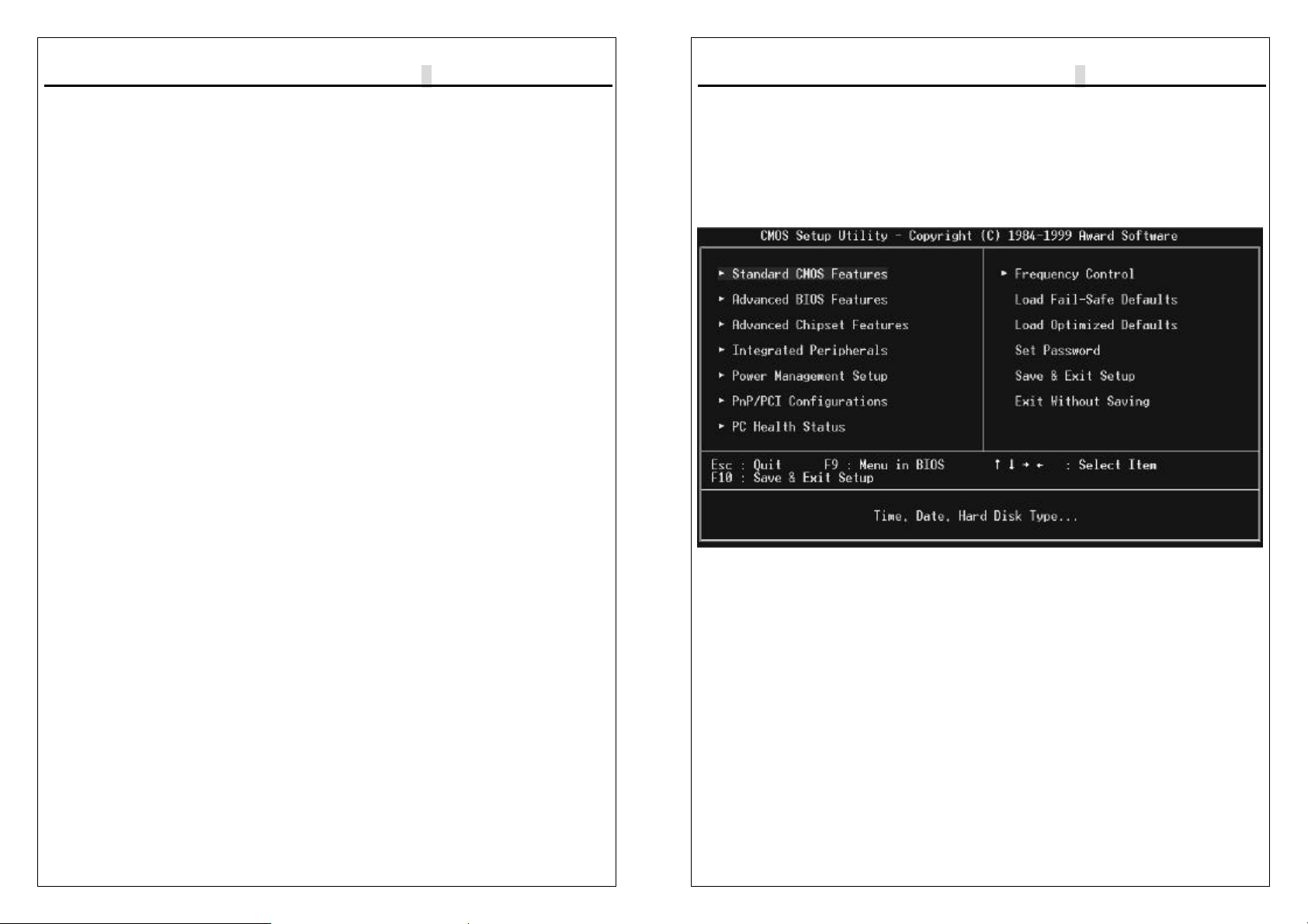
3-2 Main Menu
Once you enter the AwardBIOS™ CMOS Setup Utility, the Main Menu will appear
on the screen. The Main Menu allows you to select from several setup functions
and two exit choices. Use the arrow keys to select among the items and press
<Enter> to accept and enter the sub-menu.
Note that a brief description of each highlighted selection appears at the bottom of
the screen.
Setup Items
The main menu includes the following main setup categories. Recall that some
systems may not include all entries.
Standard CMOS Features
Use this menu for basic system configuration.
Advanced BIOS Features
Use this menu to set the Advanced Features available on your system.
9W
▄
AP/P +Serial User’s Manual
3-5
Advanced Chipset Features
Use this menu to change the values in the chipset registers and optimize your
system's performance.
Integrated Peripherals
Use this menu to specify your settings for integrated peripherals.
Power Management Setup
Use this menu to specify your settings for power management.
.
PnP / PCI Configuration
This entry appears if your system supports PnP / PCI.
Frequency/Voltage Control
Use this menu to specify your settings for frequency/voltage control.
Load Fail-Safe Defaults
Use this menu to load the BIOS default values for the minimal/stable performance
for your system to operate.
Load Optimized Defaults
Use this menu to load the BIOS default values that are factory settings for optimal
performance system operations. While Award has designed the custom BIOS to
maximize performance, the factory has the right to change these defaults to meet
their needs.
Supervisor / User Password
Use this menu to set User and Supervisor Passwords.
Save & Exit Setup
Save CMOS value changes to CMOS and exit setup.
Exit Without Save
Abandon all CMOS value changes and exit setup.
9W
▄
AP/P +Serial User’s Manual
3-6
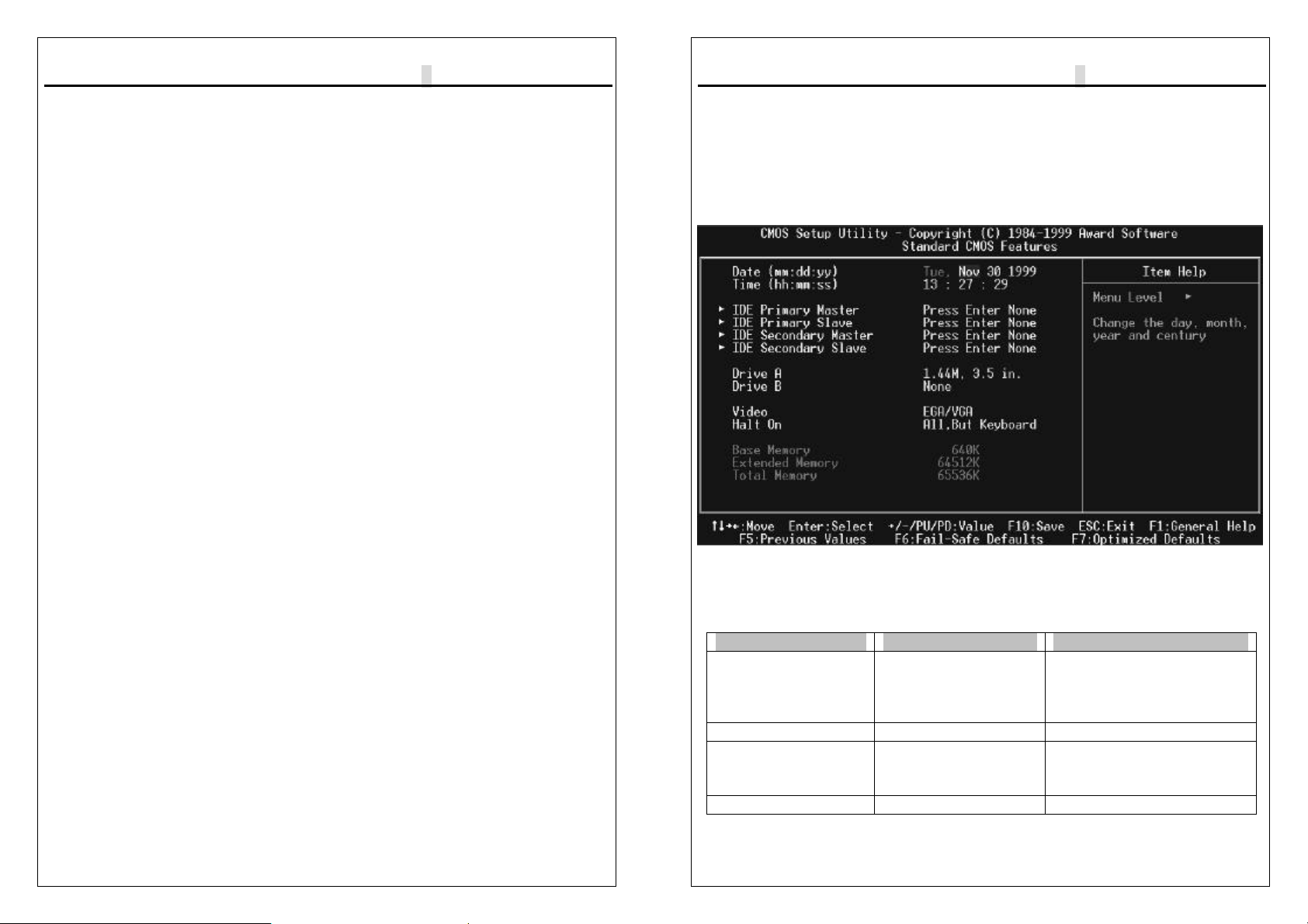
3-3 Standard CMOS Setup
The items in Standard CMOS Setup Menu are divided into 10 categories. Each
category includes no, one or more than one setup items. Use the arrow keys to
highlight the item and then use the <PgUp> or <PgDn> keys to select the value
you want in each item.
Main Menu Selections
This table shows the selections that you can make on the Main Menu
Item Options Description
Date
Month DD
YYYY Set the system date. Note
that the ‘Day’ automatically
changes when you set the
date
Time HH : MM : SS Set the system time
IDE Primary Master Options are in its sub
menu
(described in Table 3)
Press <Enter> to enter the
sub menu of detailed
options
IDE Primary Slave
Options are in its sub
Press <Enter> to enter the
9W
▄
AP/P +Serial User’s Manual
3-7
menu
(described in Table 3) sub menu of detailed
options
IDE Secondary Options are in its sub
menu
(described in Table 3)
Press <Enter> to enter the
sub menu of detailed
options
IDE Secondary Options are in its sub
menu
(described in Table 3)
Press <Enter> to enter the
sub menu of detailed
options
Drive A
Drive B None
360K, 5.25 in
1.2M, 5.25 in
720K, 3.5 in
1.44M, 3.5 in
2.88M, 3.5 in
Select the type of floppy
disk drive installed in your
system
Video EGA/VGA
CGA 40
CGA 80
MONO
Select the default video
device
Halt On All Errors
No Errors
All, but Keyboard
All, but Diskette
All, but Disk/Key
Select the situation in which
you want the BIOS to stop
the POST process and
notify you
Base Memory N/A Displays the amount of
conventional memory
detected during boot up
Extended Memory N/A Displays the amount of
extended memory detected
during boot up
Total Memory N/A Displays the total memory
available in the system
IDE Adapters
The IDE adapters control the hard disk drive. Use a separate sub menu to
configure each hard disk drive.
9W
▄
AP/P +Serial User’s Manual
3-8
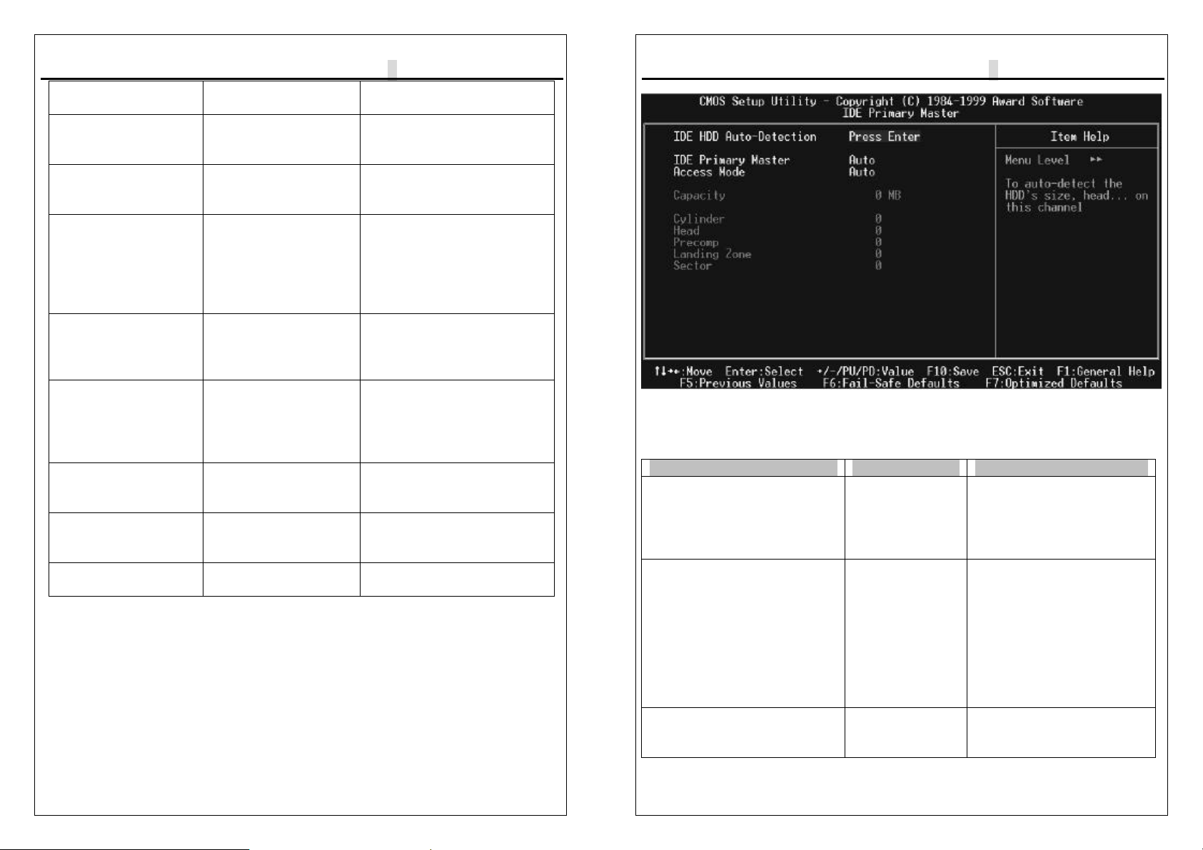
IDE Primary Master sub menu
Use the legend keys to navigate through this menu and exit to the main menu.
Item Options Description
IDE HDD Auto-detection Press Enter Press Enter to auto-detect
the HDD on this channel.
If detection is successful, it
fills the remaining fields on
this menu.
IDE Primary Master None
Auto
Manual
Selecting ‘manual’ lets you
set the remaining fields on
this screen. Selects the
type of fixed disk. "User
Type" will let you select the
number of cylinders,
heads, etc. Note:
PRECOMP=65535 means
NONE !
Capacity Auto Display
your disk drive
size
Disk drive capacity
(Approximated). Note
that this size is usually
This manual suits for next models
3
Table of contents
Other Fastfame Motherboard manuals


