Faulhaber MCBL 05002 Series User manual
MCBL 05002
Series MCBL 07002
Series
Servo Amplier
Sine Controller
for Micro Brushless DC-Motors
Operating Instructions

Subject to change without notication
ABOUT THIS HANDBOOK
1. GENERAL
1.1 BASICS
1.2 TECHNICAL DATA
1.2.1 MCBL 05002
1.2.2 MCBL 07002
2. CONNECTION
2.1 OVERVIEW
2.2 DESCRIPTION
2.2.1 Supply Voltages
2.2.2 Serial Interface
2.2.3 Analog Inputs
2.2.4 Digital Inputs
2.2.5 AUXIn as Fault Input
2.2.6 Power Outputs and Current Detector
3 CONTROL
3.1 ON THE MODULE
3.2 EXTERNAL INPUTS (PINS)
3.3 CONFIGURATION AND PROGRAMMING
3.3.1 Setup of the Programmable Interface
3.3.2 Command Syntax
3.3.3 Node Addresses and Additional Drives
3.3.4 Saving the Settings
3.4 DESCRIPTION OF OPERATING MODES
3.4.1 Continuous Mode
3.4.2 Stepper Motor Mode
3.4.3 Pointer Mode
3.5 VELOCITY CONTROL
3.5.1 Analog Speed Setup
3.5.2 Setting Velocity via Pulse Train
3.5.3 Speed and Ramps
3.5.4 Output Voltage and Back-EMF Compensation
3.5.5 Start/Stop and Direction of Rotation
3.6 POSITIONING
3.7 STEPPER MOTOR MODE
Table of Contents
Contents Page
III
1
1
3
3
3
5
5
6
6
6
6
7
7
7
8
8
9
10
10
10
11
12
13
14
15
15
16
16
18
19
20
21
22
24

Subject to change without notication
Subject to change without notication
3.8 POINTER MODE
3.9 OVERCURRENT LIMIT
4 INSTALLATION & VERIFICATION
4.1 STARTING THE MODULE
4.2 INSTALLATION WITH AN MCBL 07002
4.3 TROUBLESHOOTING
4.3.1 Drive stationary with analog input
4.3.2 Drive will not move
4.3.3 Faulty circuit or drive
4.3.4 Output voltage or speed incorrectly set
4.3.5 Other faults
5 APPENDIX
5.1 LIMIT VALUES
5.2 COMMAND SET
5.3 FACTORY CONFIGURATION
5.4 CONNECTING TO A COMPUTER
5.5 STARTER KIT MCBL 07002
5.5.1 Overview
5.5.2 Operation
Contents Page
26
27
28
28
29
30
30
30
31
31
31
32
32
33
38
39
40
40
41

Subject to change without notication
Subject to change without notication
About this Handbook
This handbook serves a number of purposes: to provide simple instructions for users so that
they can set up the electronics by themselves and put the unit into operation. This manual is
also designed to provide pertinent information on how to set and program parameters via
the command interface. It also serves as a reference manual for the drive in its daily opera-
tion, providing details of how to use commands and operate the drive according to the user’s
requirements.
The data sheet in Chapter 1.2 is very important. In Chapter 5.1 the permitted limit values of
the programming interface are listed.
Readers who are already familiar with the principles of the Faulhaber MotionController are
recommended to read Chapter 3, in which all the commands are described that are available
via the Programmer Interface. The Appendix in Chapter 5.2 gives an alphabetical overview
with brief examples of each type of command.
A summary of which input to use with which operating mode is contained in Table 1.
For the purposes of this manual is assumed that a motor without a gearbox is connected.
Otherwise, all position and speed-data must be adjusted by the gear ratio.
Conventions: Connection pins such as Start/Stop are shown in italics. Instructions for the Pro-
grammer Interface are shown in bold: ver.
© 2002 Dr. Fritz Faulhaber GmbH & Co. KG
Windows and Windows NT are registered trademarks of Microsoft Corporation.
Subject to change without notication
Subject to change without notication
1
1.1 Basics
1. General
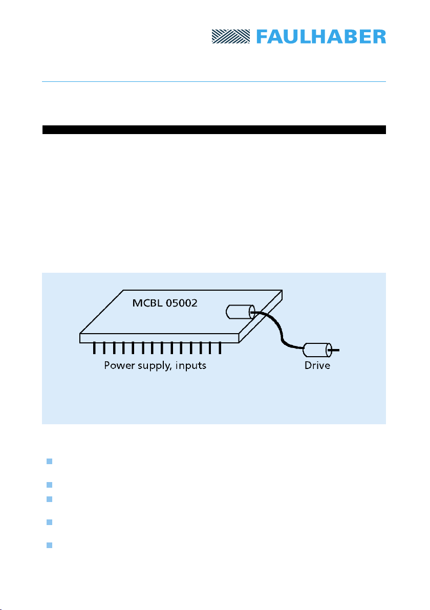
The MCBL 05002 is a general-purpose controller for three-phase brushless motors. It has small
external dimensions and can be plugged into a normal IC-socket. It is ideally suited for effec-
tive operation of 0206 micromotors, but can also be used to control any other three-phase
motor. The drive will operate in open-loop mode, with no speed feedback from the drive to
the controller.
The controller has a range of inputs, making it suitable for various types of operation.
Potentiometers can be connected via analog inputs so that the drive can be manually controlled.
If the pulse input is used, the drive can operate as a stepper motor; via a serial interface the
drive can be connected to a PC or a PLC and operated accordingly. All drive parameters can be
adjusted via this programmer interface. Parameters can be stored and retained for re-use once
the unit is switched on again.
Technology
Extremely silent-running due to control via a three-phase sinewave signal (not PWM!).
Drives with low moment of inertia also run silently.
Smooth start-up and slowdown via acceleration and deceleration ramps in all drive modes.
Safer operation due to compensation of the induced back-EMF, so that the required
torque is near-constant.
Overcurrent protection via a peak current limiter, which operates when the maximum
permitted current is exceeded, to return the drive to a safe state.
Positioning moves the drive within 4 million revolutions with a resolution of 1/256th of a
revolution.
Fig. 1: Main components
Subject to change without notication
Subject to change without notication
2
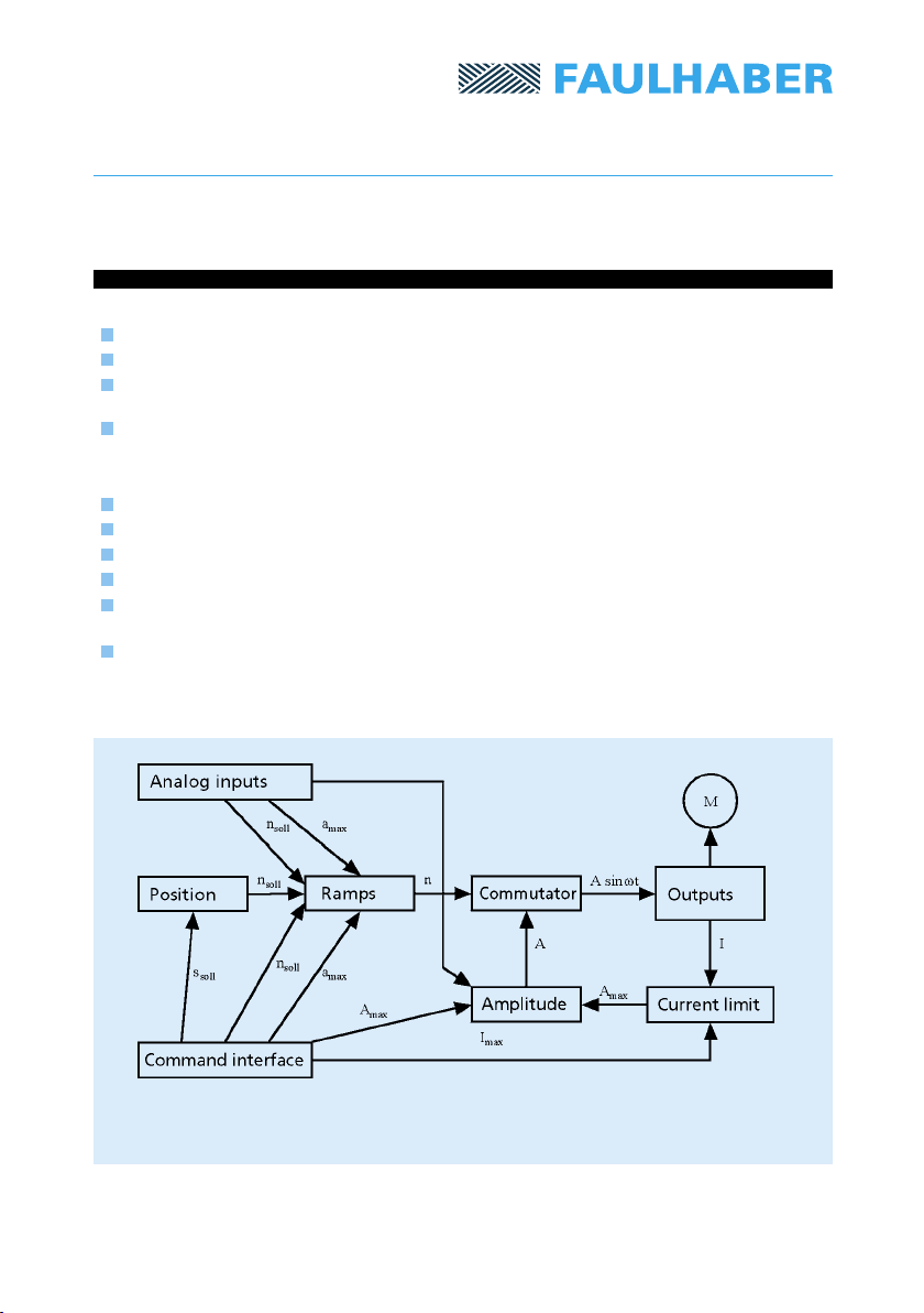
Versatility
Multiple voltage-controlled inputs to adjust speed, acceleration ramps and output voltage.
Pulse input, permitting use as a stepper motor or alternatively as a rated-speed motor.
Pointer instrument input, with which the rotor can be deected from the zero-position
in proportion to an applied analog voltage.
Serial link (RS232, RS422), enabling all parameters to be adjusted from a PLC or a PC.
Features:
Small footprint: 42 x 24 mm
Enormous speed range, from 21 rpm to 120 000 rpm with ne resolution
Powerful: 200 mA running current
Selectable common-bus or individual supply for electronics and motor
Non-volatile memory: all parameters such as speed, drive mode, target position etc.
can be stored as required and are immediately available again after power-on.
The processing performance is achieved by using a powerful 24 MHz microcontroller.
In order to put the MCBL 05002 into service quickly and without problems, a Starter Kit
MCBL 07002 is available for the laboratory. This is described in Chapter 5.5.
Fig. 2: Schematic diagram of MCBL 05002

Subject to change without notication
Subject to change without notication
1.2 Technical Data
3
V DC
mA
°C
°C
V
V
baud
mm
g
6,5 – 7,5
400
0 ... + 30
0 ... + 60
low: -8 – -5
high: 5 – 8
9 600
126 x 81 x 34
190
V DC
V DC
mA
mA
V
V
V
Ω
V
V
kHz
Ω
rpm
%
V
mA
%
°C
°C
V
V
baud
mm
g
1.2.1 MCBL 05002
4,5 – 5,5
4,5 – 7,5
70
200
low: 0 – 0,8
high: 2,4 – 5,0
0 – 5,0
> 500
low: 0 – 0,5
high: 4 – 10
200
> 2 200
0 ... 120 000
± 0,5
2,4
50 – 900
20
0 ... + 45
-25 ... + 85
low: 0 – 0,5
high: 2,4 – 5,0
9 600
42 x 24 x 11
8
1.2.2 MCBL 07002
Supply voltage:
- Electronics VS
- Power stage V+
Current consumption:
- Electronics Is
- Power output (V+ = 7V, Tamb = 25 °C) I+ max. current
Analog inputs Digital input level
(all except AUXin; Vs = 5V) (TTL-level)
Analog input level
Input resistance
AUXin Input level
max. input frequency
Input resistance
Output signals Speed
Deviation from dened values
Voltage range Veff
Ammeter Range
max. error
Temperature range:
– in service (freely ventilated)
– in storage
Interface Level (Vs = 5V)
Baud rate
(No Parity, 1 Stop bit)
Dimensions (LxWxH)
Weight
Supply voltage: VS
Current consumption: Is max. current
Temperature range:
– in operation (freely ventilated)
– in storage
Interface Level (Vs = 5V)
Baud rate
(No Parity, 1 Stop bit)
Dimensions (LxWxH)
Weight

Subject to change without notication
Subject to change without notication
4
Dimensions of the MCBL 05002
Remarks
All pins are specied to a grid measurement RM 2,54 and therefore are only indicated in outline.
The MCBL 05002 can thus be tted into an ordinary DIL28-IC socket.
RastermaB 2,54mm
DIL 28
7,69
5,73
6
12
15,25
1,94
39,6
33,41
24,62
15,23
2,6
1,6
5,4
2
42
24
ø3,5
Fig. 3
Grid size

Subject to change without notication
Subject to change without notication
Viewing the MCBL 05002 from the front: If the two big black ICs are on the top left
and the plug on the right, Pin 1 will be located on the left below. It can also be recognized
by a rectangular soldered patch. Pin 14 is below on the right, and marked with the number 14.
5
2. Connecting Up
2.1. Overview
Fig. 4: layout of the operaring elements
Function Direction Pin Description
Serial Receive IN 14 RS 232 interface with TTL levels
Serial Transmit OUT 13 RS 232 interface with TTL levels
Ramp Slope ANALOG 12 Slope of the acceleration ramp
Output Voltage 1 ANALOG 11 Amplitude of output voltage
RPM 1 ANALOG 10 Speed of the drive (frequency of the voltage)
Output Voltage 2 IN 9 Amplitude of output voltage
RPM 2 IN 8 Speed of the drive (frequency of the voltage)
Reset IN 7 Reset the controller
Direction IN 6 Direction of rotation of the drive
Start/Stop IN 5 To start and stop the drive
Vcc IN 4 Digital section supply voltage: +5V stabilized
GND IN 3 Ground (earth)
V+ IN 2 Power section supply voltage: +7.5V
Isense OUT 1 Current detector output
AUXin IN 15 Multi-function input
Phase C OUT 16 Power output to drive
Phase B OUT 17 Power output to drive
Phase A OUT 18 Power output to drive
Explanation of ANALOG: This connection is internally connected to a potentiometer with
a 1 kΩ resistance. If this connection is not made, it can be used to measure the voltage at
the potentiometer, and it thus operates as an output. By means of a drive of sufciently
low impedance, the user may set this voltage to the level that he requires;
in this mode, the connection operates as an input. The potentiometer on the board
should be set in the middle of the scale. See also the description in 2.2.3.

Subject to change without notication
Subject to change without notication
6
2.2.1 Supply Voltages
2.2 Description
Explanation of ANALOG: This connection is internally connected to a potentiometer with
a 1 kΩ resistance. If this connection is not made, it can be used to measure the voltage at
the potentiometer, and it thus operates as an output. By means of a drive of sufciently
low impedance, the user may set this voltage to the level that he requires;
in this mode, the connection operates as an input. The potentiometer on the board
should be set in the middle of the scale. See also the description in 2.2.3.
The supply voltage Vcc to the electronics section must be + 5V stabilized, and for the power
section it may be between V+ = + 5V DC and + 7,5V DC. The range of output voltage however
is always at max. 2,4Veff, independent of the supply voltage (see data sheet).
If a drive with very high power is used, it is advisable to use a supply voltage greater than 5V
for the supply section to minimize distortion of the output signal. Note that at the same time
the power loss in the power section will increase.
When connecting a micromotor 0206, output signal distortion occurs with an output voltage
of > 2200 mVeff and a voltage supply of 5V. If a 7V supply is used for the power section, these
distortions disappear.
The pins Serial Receive and Serial Transmit implement a serial link with TTL levels. To create an
RS232 interface, in order to link the micromotor control with a PC, a signal converter (MAX232
or similar) must be used to raise the levels to the corresponding + 12V and – 12V.
An RS422 link can be made to another drive, for example a MAX488. This gives the advantage
of greater immunity to disturbance.
Setup of the interfaces is described in Chapter 3.3.1.
2.2.2 Serial Interface
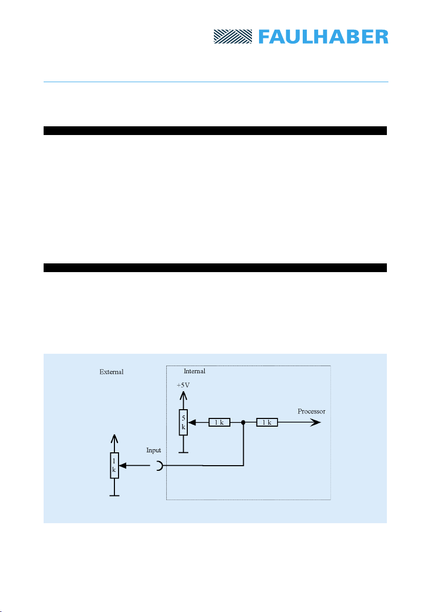
The analog inputs are suitable for voltage levels between 0V and 5V.
Ramp Slope: A voltage of 0V corresponds to a ramp of 0 revs/s2, and 5V corresponds to about
700 rpm/ms (= 11 700 1/s2). This input is shown in Fig. 5 connected via a 5 kΩ potentiometer.
If the pin is externally connected, the potentiometer should be set in the middle of its range,
in order to prevent an undesirable closed-circuit current.
Output Voltage 1 and Output Voltage 2: The voltage value of these two inputs is multiplied
internally and determines the level of the output voltage. Output Voltage 1 is connected
internally to a potentiometer as a potential divider (see also Fig. 5). This is used to adjust the
maximum voltage that can be supplied to the micromotor without damaging it. Then via
Output Voltage 2 – e.g. using an external potentiometer – the output voltage can safely be
adjusted between 0V and the preset maximum value. If Output Voltage 1 is also connected
externally, then the internal potentiometer should be set to its mid-range position, so as to
prevent a high closed-circuit current.
RPM 1 and RPM 2: Via these two inputs the speed can be adjusted over a wide range. The
measured voltages are multiplied internally to give the speed value. The response of these
inputs can be modied via the commands mv, mav and maxav.
2.2.3 Analog Inputs

Subject to change without notication
Subject to change without notication
7
2.2.4 Digital Inputs
Start/Stop is a push-button input: If a 5V signal is applied for a short time, the on/off status of
the drive is switched over. The switch occurs when the 5V signal drops again to 0V. The input
is linked internally to a pull-up resistor so that only a pushbutton to ground (earth) needs to
be connected.
Direction is a switch input: if a positive 5V signal is applied, the drive rotates to the right
(clockwise). If the signal is 0V, it rotates the other way. This input is linked internally to a
pull-up resistor so that an external switch merely has to be switched to ground (earth).
The wiring of the Start/Stop and the Direction inputs is shown in Chapter 3.2.
AUXin is an input which can be used for various purposes. If the module is operating in one
of the Position Control Modes, the user may connect a pulse train via this input, which will
determine the position/speed of the drive. The input is switched as a digital input and expects
TTL signal levels.
In Pointer Mode, the analog voltage which determines the position of the rotor is set via this
input. It expects a voltage level between 0 and 5V.
This input is triggered internally via a zener diode. When functioning as an analog input, this
may lead to a distortion of the transfer function close to 5V. If this happens, and the program-
mer interface is set to a somewhat greater amplication factor, then the full voltage range can
no longer be exploited. See Chapter 3.8.
Note: If AUXin is switched as a digital input and is expecting a pulse train, this signal must
comply with the TTL specications and be sufciently sharply-sloping to pass as quickly as pos-
sible through the undened range between LOW and HIGH. Pulse signals with very ill-dened
edges may cause oscillations in this range, which will be counted as denite pulses.
In this event, it is recommended to pre-treat the pulses via Schmitt triggers to improve the signal.
2.2.5 Fault Input
The drive is connected to the outputs Phase A, B and C. If two supply lines are changed
around, the direction of the drive will be reversed. The total current consumption of the
power supply section ows across a resistor which is shunt-connected to earth and generates
a voltage drop. This voltage drop can be monitored via the output Isense.
2.2.6 Power Outputs and Current Detector
Subject to change without notication
Subject to change without notication
8
3. Control
The module may be controlled using two different methods:
1. Electrically via the pins or via the built-in potentiometers. The speed of the drive
is proportional to either an applied analog voltage or an applied pulse train.
2. The serial interface accepts user-generated commands. Simple externally generated
commands permit a much more detailed control than is possible via the pins.
Control via electrical signals is described in Chapters 3.1 and 3.2. Control via the programma-
ble interface is covered in Chapter 3.3.
3.1 On the Module
On the module there are three potentiometers, with which the Acceleration Ramps, Output
Voltage and Speed can be set manually.
The outputs of these potentiometers are connected, via 1 kΩ resistors, to the analog inputs
of the microcontroller. Hence, these inputs can also be controlled via external potentiometers
(in this situation, the crosstalk will be minimized if the potentiometers on the module are set
to the middle of their range).
The relevant external pins are RPM 1, Output Voltage 1 and Ramp Slope.
Fig. 5: Input switching with internal potentiometer
Warning: If the voltage on an input is very close to 0V, the Analog/Digital converter will
register a 0. Then a voltage variation on the other input will produce no change in rotational
speed, since the two inputs are multiplied together internally. For such voltage variations to
produce an effect, both voltages must be sufciently far from 0V (at least 5 mV) so that a
value different from 0 can be read.

Subject to change without notication
Subject to change without notication
3.2 External Inputs (Pins)
The description of Start/Stop and Direction inputs is given in Chapter 2.2.4. Fig. 6 shows an
example of external switching.
Fig. 6: Input switching for Start/Stop and Direction
9

Subject to change without notication
Subject to change without notication
10
3.3.1 Setup of the Programmable Interface
The programmable interface is implemented as an RS-232 compatible interface (cf Chapter 2.2.2).
It enables connection to a Personal Computer (PC) or a digital controller such as a PLC or an IPC.
Communication with the PC is possible in either of two ways:
1. Via a simple ASCII terminal program, such as that included in any Windows-based operating
system. In Windows NT this is available under the name Hyperterminal.
2.
With the program Faulhaber Motion Manager available from Dr. Fritz Faulhaber GmbH & Co. KG
(can also be downloaded free of charge via the Internet at http://www.faulhaber.de), which
allows particularly simple operation of drives. In addition it can be used to display real-time
data, such as current speed, graphically.
The serial interface is congured according to the following setup. It is important to use the
same conguration in the PC and in the controller to ensure correct operation:
9600 Baud
8 Data bits
1 Stop bit
No Parity
If a terminal program is used, symbols entered will not be displayed because the local echo is
deselected. In this event the MCBL can send these symbols back to the PC, to be displayed to
the user. This is accomplished by the command echo 1.
3.3 Conguration and Programming
Communication is carried out via commands. The user types in a command to the terminal
program. When the ENTER key is pressed, the command will be sent to the MCBL and imple-
mented by it. If the command requires a feedback from the MCBL to the user, this will be
given automatically.
Commands are structured according to the following syntax:
[NODEADDRESS] [COMMAND] [PARAMETER] <Enter>
1) NODEADDRESS: If more than one drive is addressed via the same interface, this number is
the number of the corresponding drive. If it is omitted, the command will be sent to all the
connected drives (cf Chapter 3.3.3).
2) COMMAND: A character string, using only letters of the alphabet.
3) PARAMETER: In some commands the command word is followed by a number (without
alpha-characters) which is used as the argument.
4) The CR (carriage return) character is included at the end; it is entered in a terminal program
by pressing the ENTER key.
Blank spaces will be ignored, and may be added at will. No distinction is made between capital
letters and lower-case.
Some commands return data to the PC. This always takes the form of a character string, fol-
lowed by the CR and then LF (line feed) characters.
3.3.2 Command Syntax

Subject to change without notication
Subject to change without notication
11
3.3.3 Node Addresses and Additional Drives
With the assistance of an RS-232 Multiplexer Board it is possible to control several drives from
a single RS-232 interface. For this reason a feature has been included to address each drive
individually, because otherwise every command would be implemented by every drive.
This is achieved via the Node Number.
The user must give every drive an address before it is connected to the network, using the
command nodeadr, and store it with the command save (see Chapter 3.3.4).
Subsequently, the drive can be connected to the network of the RS-232 multiplexer board.
Every command will now be preceded by a number – this is the address of the drive for which
the command is intended. If no address is given, the command is sent to all the drives on the
network. If only a single drive is connected to the serial interface, the node address can be
omitted, since the command is only intended for that drive.
Command Function Description
nodeadr Dene Node Address Assign a node address (0 to 255)
gnodeadr Get Node Address Send back the node address to the system
save Save Conguration Record all drive parameters in a non-volatile
memory
Disconnect Asynchronous Response:
Some commands send a response straight back to the user. However, a few commands do
not do this immediately, but only when a certain condition is satised. For instance, np 1000
(notify position) sends a “p” back when the position 1000 has been reached.
Such asynchronous responses create a contention problem with the node addresses because
the response does not take place immediately after the sending of the command. If several
drives happen to send back a feedback at the same time, this leads to an unreadable signal.
The user or control program will be left waiting in vain for the right response. For this reason,
in any network with several drives connected, only one drive is ever allowed to send asyn-
chronous responses. For the other drives this response is deselected by answ 0.
Command Function Description
answ
Asynchronous Answer On/Off
0 – no asynchronous responses
1 – asynchronous responses enabled

Subject to change without notication
Subject to change without notication
12
3.3.4 Saving the Settings
When it is delivered, the drive has no parameters recorded. The controller selects velocity
control mode. However, the current setup conguration can be saved with the command save
by storing it in a non-volatile memory (an EEPROM). This conguration will then be recalled
when the drive is next switched on.
Warning: The command save returns the response “saved” when the data has been stored in
the memory. From commencement of the command until this response is received the power
supply must not be interrupted, otherwise the drive will be reset to its original state.
The command fcong resets the drive to its as-delivered state (i.e. factory conguration), in the
event that all the parameters become so out of adjustment that a functioning system can no
longer be set up. In this event, further assistance may also be obtained using the command base.
Command Function Description
save Save Conguration
Record all drive parameters in a non-volatile store
fcong Factory Conguration Reset everything to the as-delivered state
base Base Conguration Reset to a safe mode; the drive will rotate
slowly, with a low output voltage
Subject to change without notication
Subject to change without notication
13
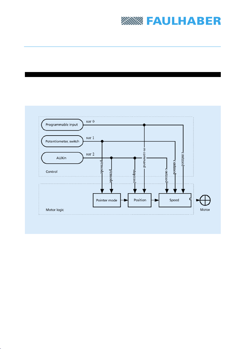
3.4 Description of the Operating Modes
The unit can be set up in either Speed Mode or Positioning Mode.
An additional Pointer Mode is available. These modes can be controlled from a variety of
input sources. The following diagram shows how the interaction between inputs and drive
modes is inuenced.
Fig. 7: Inputs and drive modes
The as-delivered MCBL application runs from analog inputs and is set to Normal Mode. This
corresponds to the commands sor 1 and contmod.
The user can control speed, output voltage and ramp rate either from built-in or external
potentiometers. If the external interface is deselected via sor 0, these parameters can be set
via the programmable interface.

Subject to change without notication
Subject to change without notication
Table 1: Modes and input options
1) Remarks:
In modes sor 1 and sor 2 positioning is not possible; the m-command will be ignored.
The way in which the drive responds is always based on a combination of the mode selected
and the input source. This is shown in Table 1, in which impracticable combinations are shown
in gray. The operating modes are now briey described in turn in the following paragraphs:
3.4.1 Continuous Mode
If the normal mode contmod is selected, inputs are taken via sor commands from three
different sources:
1. sor 1 uses analog inputs: rotational speed, ramp rate and output voltage are determined
from a total of ve analog inputs. Three of these inputs are provided via potentiometers
on the board.
2. If the drive is controlled via the programmable interface, sor 0 must be used. In this case,
the drive’s external inputs will not function.
3. If sor 2 is used, the speed is determined by a pulse train input to AUXin. A more detailed
description of this option is given in the following chapters.
A special case is positioning with lr, la und m, whilst contmod is active. It functions only when
sor 0 is used. Positioning is deselected in the other two input modes because otherwise there
would be internal conicts with the speed setup.
14
Mode Input source
sor 0 sor 1 sor 2
No external input Input via pot. 1) Input is AUXin 1)
Contmod Speed via v-command Speed via pot. Pulse train dictates
speed
contmod and Position via m-command No effect (speed via pot.) No effect (pulse train
m-command dictates speed)
Stepmod No effect (pulses will be No effect (pulses will be Pulse dictates position
counted internally) counted internally) (do not use positioning
command!)
Ptrmod No effect Pot. “velocity 1“ Analog voltage sets the
sets the rotor deection rotor deection

Subject to change without notication
Subject to change without notication
3.4.2 Stepper Motor Mode
In stepper motor mode stepmod only a single input source is used, AUXin, which is connected
with sor 2.
If sor 0 or sor 1 are used, the drive will not receive a signal and will remain stationary.
Note that if a pulse train is applied to AUXin when operating in these modes the internal
counter will continue operating. If the input is then switched to AUXin via sor 2, the accumu-
lated pulse-count will be processed and the drive will be activated immediately.
3.4.3 Pointer Mode
Pointer Mode is selected by the command ptrmod, in which the rotor angle of the drive is
maintained proportional to a voltage input to AUXin (sor 2) or alternatively to the position of
the potentiometer “velocity 1“ (sor 1).
15
Command Function Description
sor Source 2 = AUXin is used as input
1 = Analog input (pot.) is used as input
0 = All external inputs will be ignored
stepmod Stepper Motor Mode Stepper motor with position preset
ptrmod Pointer Mode Instrument pointer mode
gmode Get Mode Display the selected mode in plain text

Subject to change without notication
Subject to change without notication
3.5 Velocity Control
3.5.1 Analog Speed Setup
There are several ways to set the velocity, i.e. the rotational speed: external control may be
selected via analog voltage (Chapter 3.5.1) or a pulse train input (Chapter 3.5.2). Presetting of
a rotational speed value via the programmable interface is described in Chapter 3.5.3.
The selected mode also has an indirect effect on the rotational speed: Positioning Mode (3.6),
Stepper Motor Mode (3.7) and Pointer Mode (3.8).
16
Rotational speed is setup via the analog inputs with contmod and sor 1 (see Chapter 2.2.3).
This is also the factory delivered state of the module. The programmable interface is not
relevant in this operating mode; however, the choice of speed mode can be changed via the
programmable interface.
Fig. 8: Transfer characteristic of the analog speed setup
The drive’s rotational speed will correspond to the analog voltage at the inputs Velocity 1 and
Velocity 2. The voltage must lie between 0V and 5V. In order to guarantee exible control,
the relationship between the analog voltages and the rotational speed can be varied. Direc-
tion of rotation is determined by the Direction input, not by negative analog voltages, which
are not permitted.
With the command mav, the user presets the voltage at which the drive will start up.
This is useful for applications in which no precise 0V level is available, and in which therefore
the drive cannot be brought to full standstill. The command maxav sets the voltage at which
the drive reaches its maximum rotational speed. Maximum rotational speed is set by the com-
mand sp. Minimum speed, which is different from zero, is determined via the command mv.
The drive will run when the minimum voltage applies. At lower-level voltages it will come to rest.
This manual suits for next models
1
Table of contents
Other Faulhaber Amplifier manuals


