Faulhaber BLD 5606 Series User manual
BLD 5603 BLD 5606
Series
Operating Instructions
Servo Amplier
4-Quadrant PWM for Brushless DC-Servomotors
Series
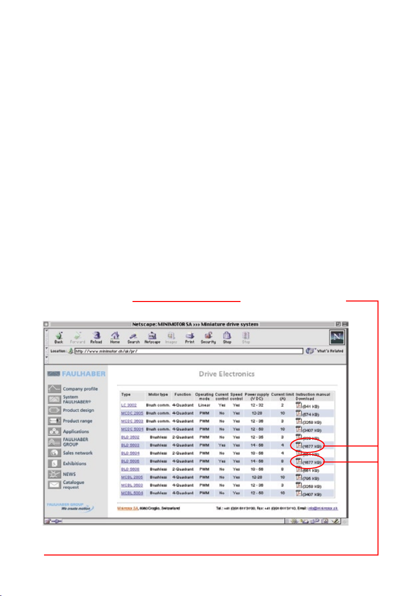
http://www.minimotor.ch/minicatalog/pdf/DriveCircuits/Manuals/IM_e_BLD_5603_5606.pdf
Surf to the following Internet
address and you will nd the
latest edition of the instruction
manual on-line: www.minimotor.ch/uk/pr/
For direct Download:
w
w
w
.
f
a
u
l
h
a
b
e
r
.
c
o
m
Miniature Drive Systems
Micro Drives
DC-Micromotors
Precision Gearheads
Servo Components
Drive Electronics

1
Index
General Information
1. Description
2. Application diagram
3. Combination possibilities
Technical Data
4. Dimensions and weight
5. Maximum ratings
6. Specic characteristics
General Characteristics
7.1 Speed regulator, type PI
7.2 Overheating protection
7.3 Current limiter, type I2t
7.4 Enable
7.5 Motor-Speed Monitor
7.6 High PWM frequency
Servo Ampliers BLD 5603-CC4P and BLD 5606-CC4P for Current Control
8. Basic circuit diagram
9. Dimensional drawing
10. Connection diagram
Servo Ampliers BLD 5603-SH4P and BLD 5606-SH4P for Speed Control
Notice of Use
Start-Up Procedure
18.1 Servo ampliers BLD 5603-CC4P and BLD 5606-CC4P for current control
18.2 Servo ampliers BLD 5603-SH4P and BLD 5606-SH4P for speed control
18.3 Servo ampliers BLD 5603-SE4P and BLD 5606-SE4P for speed control with encoder
18.4 Offset adjustment
18.5 Selection of R7 for servo ampliers BLD 5603-SH4P and BLD 5606-SH4P
18.6 Selection of R7 for servo ampliers BLD 5603-SE4P and BLD 5606-SE4P
18.7 Current limiter
18.8 Optimizing the speed regulator
18.8.1 Optimizing procedure
18.8.2 Optimizing R7
18.8.3 Load inuence
18.8.4 Function of R1, C1 and C2
Servo Ampliers BLD 5603-SE4P and BLD 5606-SE4P for Speed Control
11. Basic circuit diagram
12. Dimensional drawing
13. Connection diagram
14. Basic circuit diagram
15. Dimensional drawing
16. Connection diagram
17. Special considerations
17.1 Signal command
17.2 Power supply
17.3 Wiring

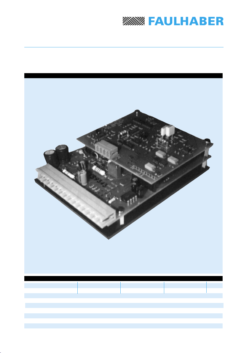
1. Description
The BLD 5603 and the BLD 5606 are 4-quadrant PWM servo ampliers suitable for the
three-phase brushless DC-servomotors, type 2036, 2444, 3056 and 3564.
The Servo Ampliers use a combination of SMD (Surface Mounted Device), MOSFET power
stage and PWM (Pulse-Width Modulation) technologies to achieve both, compact design and
high power efciency.
The basic board of the servo ampliers is a single level PCB structure, which performs all
the commutation and protective functions and contains the power stage mounted on the
heat sink plate.
The ampliers are available in two different function modes: Current control and Speed
control.
Current control (basic boards)
- BLD 5603-CC4P or BLD 5606-CC4P
In the ampliers the current owing in the active phases of the motor is regulated by the
analog current command. The ampliers are designed for use with a position controller or
in constant torque applications.
Speed control (two amplier congurations are available)
– BLD 5603-SH4P or BLD 5606-SH4P > the type SH4P uses the Hall sensor signals of the
brushless DC-servomotor to allow precise regulation at speed above 1000 rpm.
– BLD 5603-SE4P or BLD 5606-SE4P > the type SE4P is able to regulate at much lower
speeds, depending on the encoder resolution. Typical speed with 500 line encoder down
to 20 rpm.
These two servo ampliers consist of the basic board with optional modules.
These modules have a special frequency-to-voltage converter, allowing accurate
motor speed control and are provided with a current limiter function, type I2t.
The maximum continuous output power without additional heat sink is 220 W.
For ease of installation a loose female terminal block is supplied together with the main
board connector.
General Information
2Specications subject to change without notice
BLD 5603-CC4P
BLD 5606-CC4P
BLD 5603-SH4P
BLD 5606-SH4P
BLD 5603-SE4P
BLD 5606-SE4P
5500
5500
2036 U ... B, 2444 S ... B
3056 K ... B, 3564 K ... B
2036 U ... B, 2444 S ... B
3056 K ... B, 3564 K ... B
2036 U ... B, 2444 S ... B
3056 K ... B, 3564 K ... B
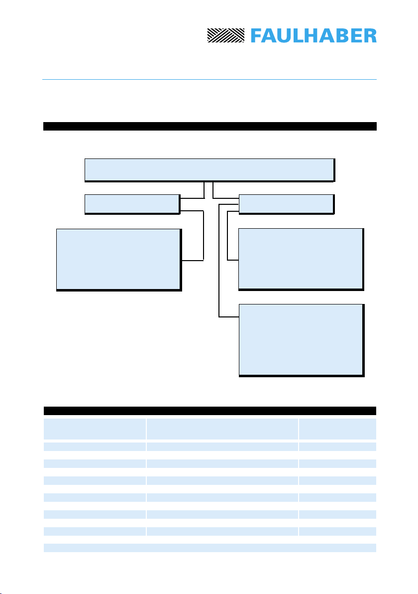
3.
3
2.
Servo Ampliers BLD 5603 and 5606
The Servo Ampliers type
BLD 5603-SE4P and
BLD 5606-SE4P are the
basic board with an additional
module for speed control of
brushless DC-Servomotors
with an additional encoder.
Current control Speed control
The Servo Ampliers type
BLD 5603-CC4P and
BLD 5606-CC4P are the
basic board suitable for the
current control (torque control)
of brushless DC-Servomotors.
The Servo Ampliers type
BLD 5603-SH4P and
BLD 5606-SH4P are the
basic board with an additional
module for speed control of
brushless DC-Servomotors
Application diagram
General Information
Servo Ampliers
Type
Encoders
Type
Brushless DC-Servomotors
Type
Combination possibilities
Specications subject to change without notice
CC4P SH4P SE4P
119,3 x 90,5 x 29 119,3 x 90,5 x 37 119,3 x 90,5 x 37 mm
195 225 225 g
4
Technical data
Format (L x W x H)
Weight
Specications subject to change without notice
4. Dimensions and weight

5
Technical data
to
Specications subject to change without notice
14 ÷ 56 14 ÷ 56 14 ÷ 56 V DC
2,0 2,0 2,0 V DC
150 150 150 kHz
0,6 / 1,2 – – A/V
4 / 8 4 / 8 4 / 8 A
±5 ±5 ±5 V DC
20 220 150 kΩ
23 0.1 1 kHz
TTL TTL TTL
+5 +5 +5 V DC
–5 –5 –5 V DC
60 140 140 mA
40 000 1000 ÷ 40 000 40 000 rpm
– 40 40
0 … +70 0 … +70 0 … +70 ˚C
–20 … +80 –20 … +80 –20 … +80 ˚C
1)
2)
3)
4)
Power stage:
– Power supply
– Total output voltage drop (Imotor = 4A)
Switching frequency
Transconductance gain
(BLD 5603/BLD 5606)
Current limit1) (BLD 5603/BLD 5606)
Analog input command:
– Voltage range 2)
– Input resistance
– Frequency bandwidth
Logical input
Ouptput voltage for external use:
– Positive (50 mA max. load)
– Negative ( 5 mA max. load)
Total stand-by current, typical
(Hall sensors included)
Speed range 3) to to
Dynamic range 4)
Temperature range:
– Operating temperature
– Storage temperature
Cycle by cycle current limiting.
Analog input command (positive voltage = CW – negative voltage = CCW)
may be set by an external potentiometer or an external voltage.
Depending on the motor type and/or encoder characteristics.
Maximum to minimum controllable speed ratio: nmax/nmin.
6. CC4P SH4P SE4P
Specic characteristics
5.
56 V DC
–6 +6 V DC
4 A
Maximum ratings
Power supply
Analog and logic inputs
Continuous output current @TA = 25˚C
7.
0
n,I
Ilim
t
Ip1 Ip2
Ic2
Ic1
Ic3
t1t2t3t4t5
n=
I =
t =
6
General characteristics
7.1 Speed regulator, type PI
A Speed Regulator type Proportional Integrator (PI) controls a brushless DC-servomotor with
no steady-state error (step input command).
7.2 Overheating protection
The servo amplier automatically shuts off if the heat sink temperature exceeds +75 ˚C.
A temperature below +70 ˚C will restart the servo amplier.
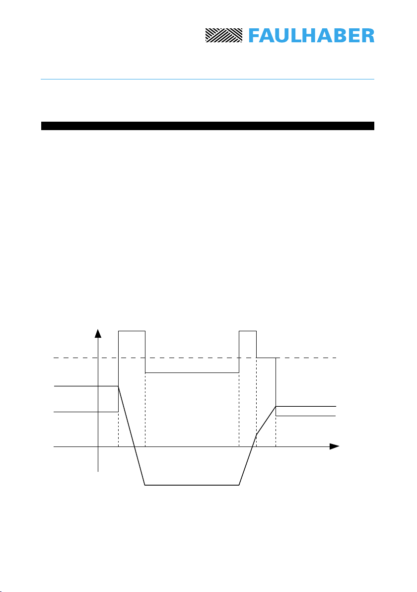
7.3 Current limiter, type I2t
A brushless DC-servomotor tolerates peak currents much higher than the maximum
continuous current admissible, though only for a limited period of time. A current limiter,
type I2t, takes these characteristics into account and, in addition, provides excellent protection
against a possible overload.
To illustrate the operation of this current limiter, the following gure provides an example of
a brushless DC-servomotor operating in an Acceleration-Constant Speed-Deceleration cycle.
motor speed [rpm]
motor current [A]
time [s]
General characteristics
Specications subject to change without notice

Ip[A] – Ic[A]
T[s] = 10,34 [s] loge
Ip[A] – Ilim [A]
7
peak current
continuous current
max. continuous admissible current
The continuous current limit, Ilim, is set according to the specic application. From the above
gure one can deduce that for t < t1, the motor is fed by a current less than the current limit.
In the deceleration phase (interval t1, t2), the current assumes the value Ip1 > llim.
The presence of the limiter allows the power rating to be exceeded without any risk to the
motor. The maximum overload period of the motor T[s] depends directly on the peak current
value and on the actual current before the overload:
In the event of an overload period longer than the maximum T period, the servo amplier will
impose the current Ilim which will continue for the duration of the overload (e.g.: interval [t4, t5]).
N.B.: When the limiter is active, the servo amplier has no control on the motor speed.
7.4 Enable
The servo amplier is disabled when contacts 7 and 11 are connected (high level).
Opening this connection (low level) enables the power stage. This input is for contact
closures only (e.g.: relay contacts).
7.5 Motor-Speed Monitor
The Motor-Speed Monitor (contact 15 of the connector), generates a voltage proportional
to the actual motor speed.
7.6 High PWM frequency
The high PWM frequency of 150 kHz allows the servo amplier to exploit the technical
characteristics of brushless DC-servomotors to the utmost.
Ip =
Ic =
Ilim =
General characteristics
Specications subject to change without notice

BLD 5603-CC4P
BLD 5606-CC4P
9.
8.
9.
+–
+5V –5V
114,3
24
90,5
119,3
18,8
65
4x M3
6,5 50
BLD 5603/06
MINIMOTOR SA
Swiss made
29
1
2
3
4
5
6
7
8
9
10
11
12
13
14
15
MSTB 2,5/15-ST
(Phoenix contact)
MSTBA 2,5/15-G
(Phoenix contact)
8
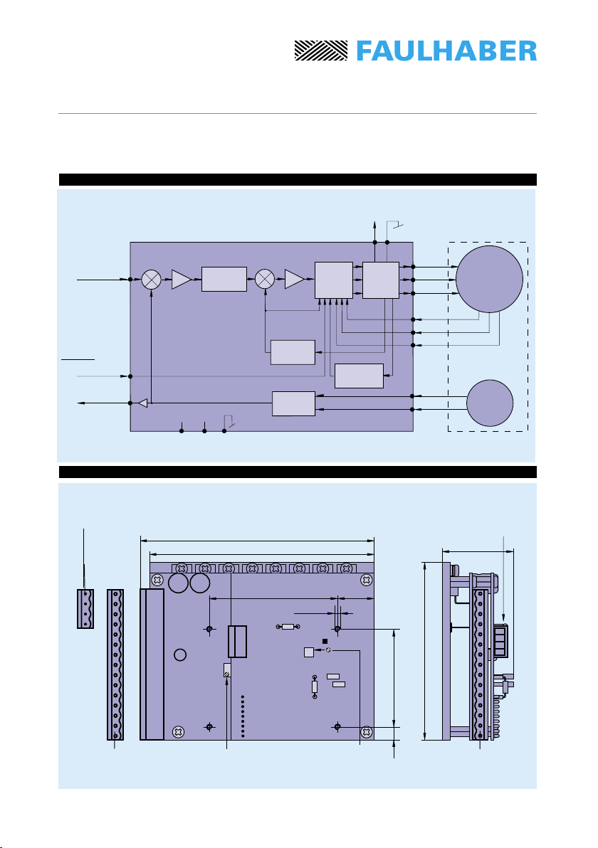
Current
command
GND logical
Current
amplier
Controller
Brushless
DC-Servomotor
Power
stage
Current
feedback
Thermal
shutdown
Ph A
Ph B
Ph C
Hs A
Hs B
Hs C
Dimensional drawing
GND
Enable
Vm
For combination with:
Brushless DC-Servomotors: 2036, 2444, 3056, 3564
Basic circuit diagram
Scale
reduced
Female terminal block,
type: Pot. : Offset
trimmer adjustment
Specications subject to change without notice
Servo Ampliers for current control
Male terminal block,
type:

BLD 5603-CC4P
BLD 5606-CC4P
1
2
3
4
5
6
7
8
9
10
11
12
13
14
15
+5V
+5V
+5V
+5V
–5V
10kΩ
9
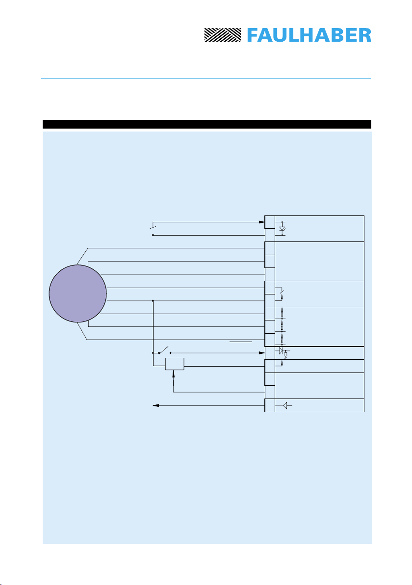
10.
Servo Ampliers for current control
Connection diagram
GND
14 ÷ 56V Vm
Phase A
Phase B
Phase C
GND logical
Logical supply +5V
Hall sensor C
Hall sensor B
Hall sensor A
Enable
Supply -5V
Current command
Before connecting it is recommended to read chapter 17, Special considerations.
Logical supply
output
Power supply
Phase output
Hall sensors
Logical command
Analog
command
Brushless
DC-Servomotor
Brown
Orange
Yellow
Black
Red
Grey
Blue
Green
Specications subject to change without notice
For combination with:
Brushless DC-Servomotors: 2036, 2444, 3056, 3564

BLD 5603-SH4P
BLD 5606-SH4P
9.
11.
12.
+
–+–
I2t
+5V –5V
114,3
37
90,5
119,3
18,8
65
4x M3
6,5
50
BLD 5603/06
MINIMOTOR SA
Swiss made
1
2
3
4
5
6
7
8
9
10
11
12
13
14
15
R7
R1 C2
C1
Test point TP
10
MSTBA 2,5/15-G
(Phoenix contact)
MSTB 2,5/15-ST
(Phoenix contact)
Dimensional drawing
Servo Ampliers for speed control
For combination with:
Brushless DC-Servomotors: 2036, 2444, 3056, 3564
Speed
command
Controller
Brushless
DC-Servomotor
Power
stage
Current
feedback
Thermal
shutdown
Ph A
Ph B
Ph C
Hs A
Hs B
Hs C
GND
Speed
amplier
Current
limiter
Current
amplier
F/V
converter
GND logical
Enable
Motor-Speed
Monitor
Vm
Speed feedback
Scale
reduced
Pot.
:
Offset trimmer
adjustment
Pot. :
Current
Limiter
Female terminal block,
type:
Basic circuit diagram
Male terminal block,
type:
Specications subject to change without notice
13.
11
1
2
3
4
5
6
7
8
9
10
11
12
13
14
15
+5V
+5V
+5V
+5V
–5V
10kΩ
BLD 5603-SH4P
BLD 5606-SH4P
Servo Ampliers for speed control
Connection diagram
GND
14 ÷ 56V Vm
Phase A
Phase B
Phase C
GND logical
Logical supply +5V
Hall sensor C
Hall sensor B
Hall sensor A
Enable
Supply -5V
Speed command
Motor-Speed Monitor
Before connecting it is recommended to read chapter 17, Special considerations.
Logical supply
output
Power supply
Phase output
Hall sensors
Logical command
Analog
command
Brushless
DC-Servomotor
Brown
Orange
Yellow
Black
Red
Grey
Blue
Green
Specications subject to change without notice
For combination with:
Brushless DC-Servomotors: 2036, 2444, 3056, 3564
9.
14.
15.
114,3 37
90,5
119,3
18,8
65
4x M3
6,5 50
BLD 5603/06
MINIMOTOR SA
Swiss made
1
2
3
4
5
6
7
8
9
10
11
12
13
14
15
R7
R1 C2
C1
Test point TP
1a
2a
3a
4a
BLD 5603-SE4P
BLD 5606-SE4P
+
–+–
I2t
+5V –5V
12
Female terminal block,
type: MSTB 2,5/15-ST
(Phoenix contact)
Male terminal block,
type: MSTBA 2,5/15-G
(Phoenix contact)
Pot. :
Current
Limiter
Male terminal block,
type: MC 1,5/4-ST 3,81
(Phoenix contact)
Pot.
:
Offset trimmer
adjustment
Female terminal block,
type: MC 1,5/4-G-3,81
(Phoenix contact)
Scale reduced
GND logical
Controller
Power
stage
Current
feedback
Thermal
shutdown
GND
Speed
amplier
Current
limiter
Current
amplier
F/V
converter
Ch A
Ch B
Brushless
DC-Servomotor
Encoder
Vm
Speed
command
Ph A
Ph B
Ph C
Hs A
Hs B
Hs C
Enable
Motor-Speed
Monitor
Dimensional drawing
Servo Ampliers for speed control
Basic circuit diagram
Speed feedback
Specications subject to change without notice
For combination with:
Brushless DC-Servomotors: 2036, 2444, 3056, 3564
Encoders: 5500

16.
BLD 5603-SE4P
BLD 5606-SE4P
1
2
3
4
5
6
7
8
9
10
11
12
13
14
15
+5V
+5V
+5V
+5V
–5V
10kΩ
1a
2a
3a
4a
+5V
+5V
+5V
13
Servo Ampliers for speed control
Connection diagram
GND
14 ÷ 56V Vm
Phase A
Phase B
Phase C
GND logical
Logical supply +5V
Hall sensor C
Hall sensor B
Hall sensor A
Enable
Supply -5V
Speed command
Motor-Speed Monitor
Before connecting it is recommended to read chapter 17, Special considerations.
Logical supply
output
Power supply
Phase output
Hall sensors
Logical command
Analog
command
Encoder Encoder
* Encoder cable supply on request
GND logical
Channel B
Channel A
+Vcc
Brown
Orange
Yellow
Black
Red
Grey
Blue
Green
* Black
* Brown
* White
* Red
Specications subject to change without notice
For combination with:
Brushless DC-Servomotors: 2036, 2444, 3056, 3564
Encoders: 5500
Brushless
DC-Servomotor

17.
14
Notice of Use
Special considerations
17.1 Signal command
The signal command is given by an external voltage of ± 5 Volts or by a potentiometer
connected directly to the servo amplier. The total potentiometer resistance must be between
10 kΩ and 47 kΩ. Before connecting it is recommended to read this chapter to obtain a good
operation of the brushless DC-Servomotor.
17.2 Power supply
Any unstabilized DC power supply voltage within the servo amplier range (14V ≤ Vm ≤ 56V)
may be used, although it is advisable to keep this voltage as low as possible in order to
minimize the EMI noise. Thus the optimum power supply is given by the following relation:
with: R, kE = Terminal resistance (phase to phase) and Back-EMF constant of the motor
Imax, nmax = Maximum current and speed reached by the motor in your specic application.
17.3 Wiring
A well known disadvantage of Pulse Width Modulation, PWM, is the large amount
of interferences generated. This has two consequences, namely perturbations to the
environment and self-perturbations.
The EMI is generated in the motor power leads and induced in the Hall sensor wires.
The smooth running of the motor is therefore perturbated and even in some cases,
the motor will not run at all.
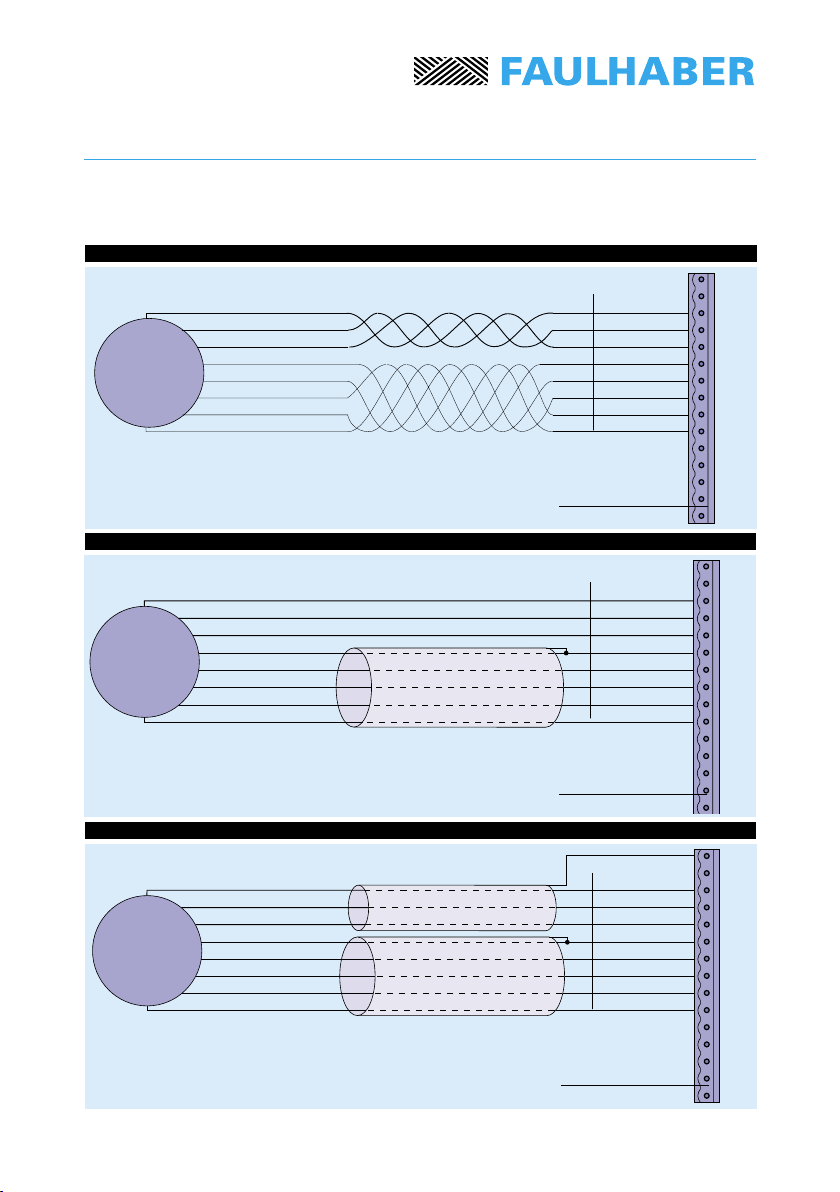
In order to reduce the effect of these perturbations, there are some basic rules to follow:
• Use wires as short as possible;
• Avoid to run signal wires (logical and analog commands, Hall sensor and encoder signals)
in close proximity to power lead wires (power supply and servomotor phases);
• Connect shielded wires to ground at one end only to avoid ground loops.
Specications subject to change without notice
Vm [V] ≈ 5 [V] + R [Ω] · Imax [A] + kE [V/rpm] · nmax [rpm]

15
1. No special care no no no 0,3 m
2. Twisted wires (see gure 1) slightly slightly slightly 1,0 m
3. Shielded Hall sensor wires (see gure 2) no yes yes 5,0 m
4. Shielded Hall sensor and phases wires yes yes yes 5,0 m
(see gure 3)
To: perturbations To environment reduced
From: perturbations From environment reduced
Self: self-perturbations reduced
Length: maximum cable length
In case of wires longer than the standard product (0,3 m), it is recommended to use
the following cable sections:
Phase, brushless DC servomotors type, 2036 ... B, 2444 ... B: 1,0 mm2 / AWG 18;
Phase, brushless DC servomotors type, 3056 ... B, 3564 ... B: 1,5 mm2 / AWG 16;
Hall sensors, brushless DC servomotors 2036, 2444, 3056 and 3564: 0,5 mm2 / AWG 20;
Note: If wires longer than 5 m please consult us.
Notice of Use
Specications subject to change without notice
Action To From Self Length
Special care should be given to the motor connection.
The following table summarize the different solutions:
16
1
2
3
4
5
6
7
8
9
10
11
12
13
14
15
1
2
3
4
5
6
7
8
9
10
11
12
13
14
15
1
2
3
4
5
6
7
8
9
10
11
12
13
14
15
Twisted wires
Shielded phase and Hall sensor wires
Figure 3
Brown
Orange
Yellow
Black
Red
Grey
Blue
Green
Phase A
Phase B
Phase C
GND logical
Logical supply +5V
Hall sensor C
Hall sensor B
Hall sensor A
Shielded Hall sensor wires
Figure 1
Figure 2
Brown
Orange
Yellow
Black
Red
Grey
Blue
Green
Phase A
Phase B
Phase C
GND logical
Logical supply +5V
Hall sensor C
Hall sensor B
Hall sensor A
Brown
Orange
Yellow
Black
Red
Grey
Blue
Green
Phase A
Phase B
Phase C
GND logical
Logical supply +5V
Hall sensor C
Hall sensor B
Hall sensor A
Brushless
DC-Servomotor
Notice of Use
Specications subject to change without notice
Brushless
DC-Servomotor
Brushless
DC-Servomotor
Connector
Connector
Connector

18.1
18.2
18.3
18.4
17
Start-up Procedure
Procedure
- Connect the servo amplier
- Power the servo amplier
- Adjust offset
References
10. Connection diagram
18.4 Offset adjustment
Procedure
- Connect the servo amplier
- Adjust offset
- Connect SE4P module to encoder
- Select R7, R1, C1 and C2
- Set current limit
References
16. Connection diagram
18.4 Offset adjustment
18.6 Selection of R7 for servo amplier
BLD 5603/06-SE4P
7.3 and 18.7 Current limiter
References
13. Connection diagram
18.4 Offset adjustment
18.5 Selection of R7
for servo amplier BLD 5603/06-SH4P
7.3 and 18.7 Current limiter
Procedure
- Connect the servo amplier
- Adjust offset
- Select R7, R1, C1 and C2
- Set current limit
Offset adjustment
The offset is adjusted changing potentiometer Pot. , (the position is indicated in
chapters 9,12 and 15 "Dimensional drawing").
Important: This setting is made by Minimotor (potentiometer Pot. sealed), hence
no other intervention is required.
Specications subject to change without notice
Servo Ampliers BLD 5603/06-CC4P for current control
Servo Ampliers BLD 5603/06-SH4P for speed control
Servo Ampliers BLD 5603/06-SE4P for speed control with encoder

9.
18.5
18
Start-up Procedure
Select resistor R7 adapted to the specic application considering also the motor
characteristics (see data sheets):
Selection of R7 for Servo Ampliers BLD 5603/06-SH4P
nmax [rpm] – max. controllable speed;
Gain [rpm/V] – gain factor of servo amplier; corresponds to ratio
between motor speed and speed command.
Resistor R7 mounted originally: 11KΩ / 0.6W / 1%.
Brushless DC servomotor 3564 K 024 B; max. speed of motor in this application
nmax = 8 000 rpm.
1. Selection of resistor R7:
R7 = 33 kΩ, resulting in a max. speed of 10 000 rpm, values slightly above 8 000 rpm
allows to operate in a broad speed range.
2. Knowing the dynamic range ( = 40) of the amplier allows to calculate the min.
controllable speed for this application, i.e.: 10 000 rpm / 40 = 250 rpm. However this
min. speed of 250 rpm is not reachable, the min. speed reachable with the SH4P
module is approx. 700 rpm and depends on a large extent of the specic application.
In general, for applications for a speed below 1 000 rpm, the use of servo amplier
BLD 5606-SE4P or BLD 5603-SE4P is recommended.
Application 1:
Table 1: Values of components R1, C1 and C2 recommended
for different speed ranges (R7)
For detailed description of components R7, R1, C1 and C2 see chapter:
18.8. “Optimizing the speed controller”.
40 000 8,2 8 140
30 000 11 6 090
20 000 16 4 180
15 000 22 3 040
10 000 33 2 040
nmax [rpm] R7 [kΩ] Gain [rpm/V]
8,2 240 1 22
11 240 1 22
16 150 1 22
22 150 1 22
33 120 1 33
Specications subject to change without notice
R7 [kΩ] R1 [kΩ] C1 [µF] C2 [nF]
This manual suits for next models
7
Table of contents
Other Faulhaber Amplifier manuals


Popular Amplifier manuals by other brands

WILSON PRO
WILSON PRO PRO 1100 installation guide

Axxent
Axxent AX-1121TS user manual

Teac
Teac A-X5030 owner's manual

Origin Acoustics
Origin Acoustics A1250 installation manual

Krell Industries
Krell Industries Evolution Owner's reference

Powerwave Technologies
Powerwave Technologies G3S-800-180-29 Installation & service manual


