Faulhaber Series BLD 3502 User manual
BLD 3502
Series
Operating Instructions
Servo Amplifier
2-Quadrant PWM for Brushless DC-Servomotors
http://www.minimotor.ch/minicatalog/pdf/DriveCircuits/Manuals/IM_BLD_3502.pdf
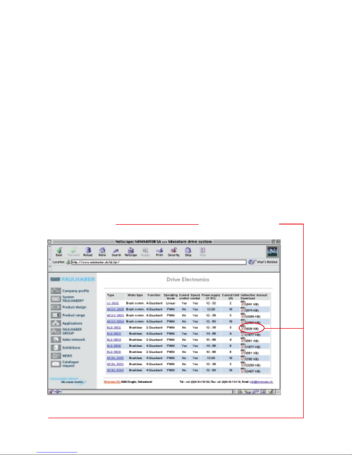
www.minimotor.ch/uk/pr/
For direct Download:
w
w
w
.
f
a
u
l
h
a
b
e
r
.
c
o
m
Miniature Drive Systems
Micro Drives
DC-Micromotors
Precision Gearheads
Servo Components
Drive Electronics
Surf to the following Internet
address and you will find the
latest edition of the instruction
manual on-line :

1
Index
1. Description
2. Illustration
General information
3. Maximum ratings
4. Specific characteristics
5. Dimensions and weight
6.1 Analog Speed command
6.2 Direction
6.3 Enable
6.4 Brake
6.5 Power supply internal fuse
6.6 Encoder feedback
6.7 Basic block diagram for speed control with Hall sensor feedback
6.8 Basic block diagram for speed control with encoder feedback
8.1 Power supply
8.2 Wiring
Notice of use
Start-up procedure
7.1 Brushless DC-Servomotor with Hall sensors feedback (standard)
7.2 Connection diagram
7.3 Brushless DC-Servomotor with encoder feedback (optional)
7.4 Connection diagram
7.5 Brushless DC-Servomotor with encoder IE2 – 512
7.6 Connection diagram
7.7 Speed range selection with Hall sensors feedback
7.8 Speed range selection with encoder feedback
General characteristics
Technical data
1.
2
2.
General information
Description
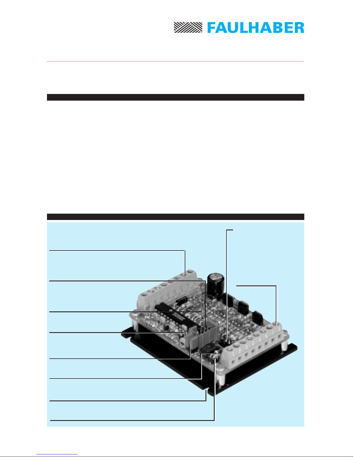
Illustration
Figure 1
Specifications subject to change without notice
Connector X2
to connect power supply and
command signal wires
Connector X3
to connect the
optional encoder.
Heat sink with four
mounting slots Ø 3,2 mm
Fuse F1
security for the power supply
input
The BLD 3502-SE2P is a 2-Quadrant PWM (Pulse-Width Modulation) Servo Amplifier suitable
for speed control of our three-phase brushless DC-Servomotors, type 1628, 2036 and 2444.
The phase commutation sequence of the brushless DC-Servomotor is automatically made by
the Servo Amplifier.
A specially designed frequency-to-voltage converter allows precise speed regulation
(regulator type P, proportional).
Two amplifier configurations for speed control:
• Hall sensors signals for operation above 1000 rpm;
• Encoder signals for operation down to 100 rpm.
The Servo Amplifier is supplied with Hall sensor configuration as standard.
The analog speed command is a unipolar signal, from 0 to +5 V, (optional 0 to +10 V)
producing a fixed speed proportional to the input voltage.
The maximum output power without additional heat sink is 50 W.
Resistance R20
for optional 0 to 10 V ASC
Resistance R13
modifies the gain
Capacitor C7
modifies the gain
Connector X5
used with encoder
IE2 – 512
Connector X1
to connect the
brushless DC-Servo-
motor wires
Connector X4
when used with encoder
both jumpers must be removed
3
5.
3502-SE2P
77
6,4
65
1 2 3 4 5 6 7 8
3
26
X1
X2
1
1
8
8
3,2
64
±1
C1
F1
R13
R20
X3
X4
1
4
C7
X5
12
56
3.
4.
Specifications subject to change without notice
Technical data
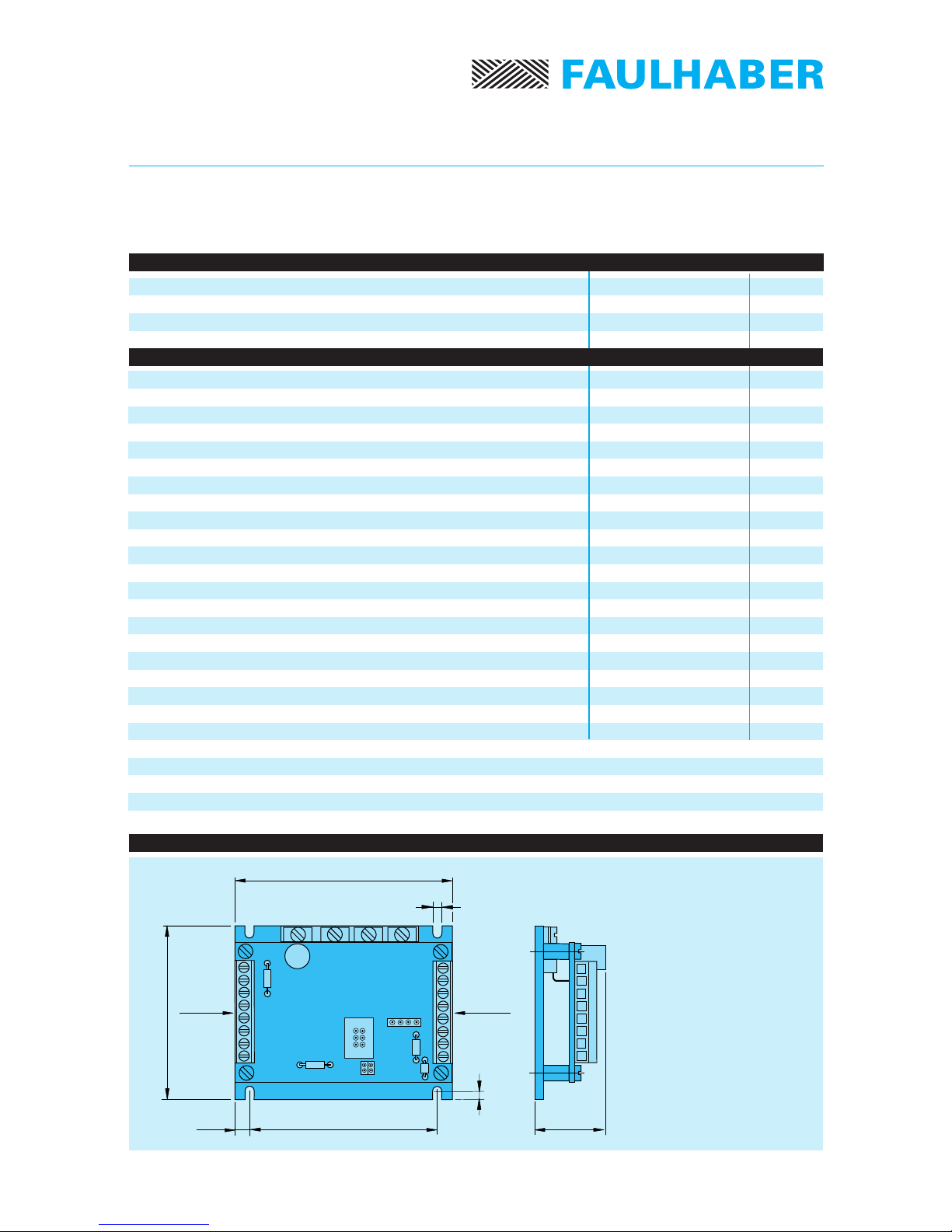
Dimensions and weight
Figure 2
Dimensions
length 77 mm
width 65 mm
height 26 mm
Weight 100 g
Scale reduced
1) Analog speed command may be set by an external potentiometer or an external voltage.
2) The maximum controllable speed depends on the gain of the Servo Amplifier,
the power supply, the motor type and the load.
3) The minimum controllable speed depends on the motor type and the load.
Power Stage:
– Power supply
– Total output voltage drop (Imotor =2A)
Switching frequency
Current limit (pulse-by-pulse current limiting)
Analog speed command: 1)
– Voltage range
– Input resistance
– Frequency bandwidth
Logic inputs
Output voltage for external use (max. load 50 mA)
Total standby current without encoder
(Hall sensors supply included)
Maximum controllable speed with Hall sensor 2)
Minimum controllable speed with Hall sensor 3)
Minimum controllable speed with encoder 3)
Temperature range:
– Operating temperature
– Storage temperature
Power supply
Logic and analog inputs
Continuous output current @ TA= 22°C
Maximum ratings
Specific characteristics
35 V DC
-0,3 to +10 V DC
1,5 A
12 ÷35 V DC
3,8 V DC
25 kHz
3A
0 ÷5VDC
36 kΩ
117 Hz
TTL
5,5 V DC
55 mA
60 000 rpm
1 000 rpm
100 rpm
0 ... + 70 °C
–20 ... + 80 °C

4Specifications subject to change without notice
General characteristics
6. General characteristics
6.1 Analog Speed command
The speed command is given by an external voltage from 0 to +5 V (optional 0 to +10 V)
or by a potentiometer connected directly to the Servo Amplifier (see fig. 5). The total
potentiometer resistance must be between 10 kΩand 47 kΩ.
Furthermore, a PWM signal with a maximum amplitude of 5 V and a minimum frequency of
1 kHz, can be used as speed command.
To control the Servo Amplifier using an analogue speed command voltage
from 0 to +10 V, it is necessary to change the R20 resistance value from 18 kΩ(standard) to
5,6 kΩ.
6.2 Direction
The direction of rotation is reversed using either a logic high or low input signal.
If not connected (internal pull-up resistance) or a high input signal is applied,
the motor runs in CW direction.
If a low input signal is applied, the motor runs in CCW direction.
6.3 Enable
A high logic at this input causes the motor run.
If not connected (internal pull-up resistance) the Servo Amplifier is enabled.
6.4 Brake
A logic low state (connect to GND) at this input allows the motor to run.
6.5 Power supply internal fuse
An internal F1 fuse is provided on the print board to protect the Servo Amplifier against:
- power supply polarity inversion
- over-load (over-current).
Fuse specification:
2A / 125V - subminiature fuse / Littelfuse type 251.002HE
6.6 Encoder feedback
The option with encoder allows the two incremental encoder channels to be used to
control the motor speed down to 100 rpm.
To use this speed control configuration it is necessary to remove the two jumpers on X4.
Refer to the start-up procedure point 7.3.
5
A
B
C
A
B
C
*
+–
+5,5V
GND
A
B
C
A
B
C
*
+–
+5,5V
A
B
GND
* Current limiting
GNDVm
Speed
amplifier BLM
Driver
F/V
converter
Phase
Phase
Phase
Hall sensor
Hall sensor
Hall sensor
Brushless
DC-Servomotor
1628 ... B
2036 ... B
2444 ... B
Logic
Analog speed
command
Direction
(CW/CCW)
Brake
Enable
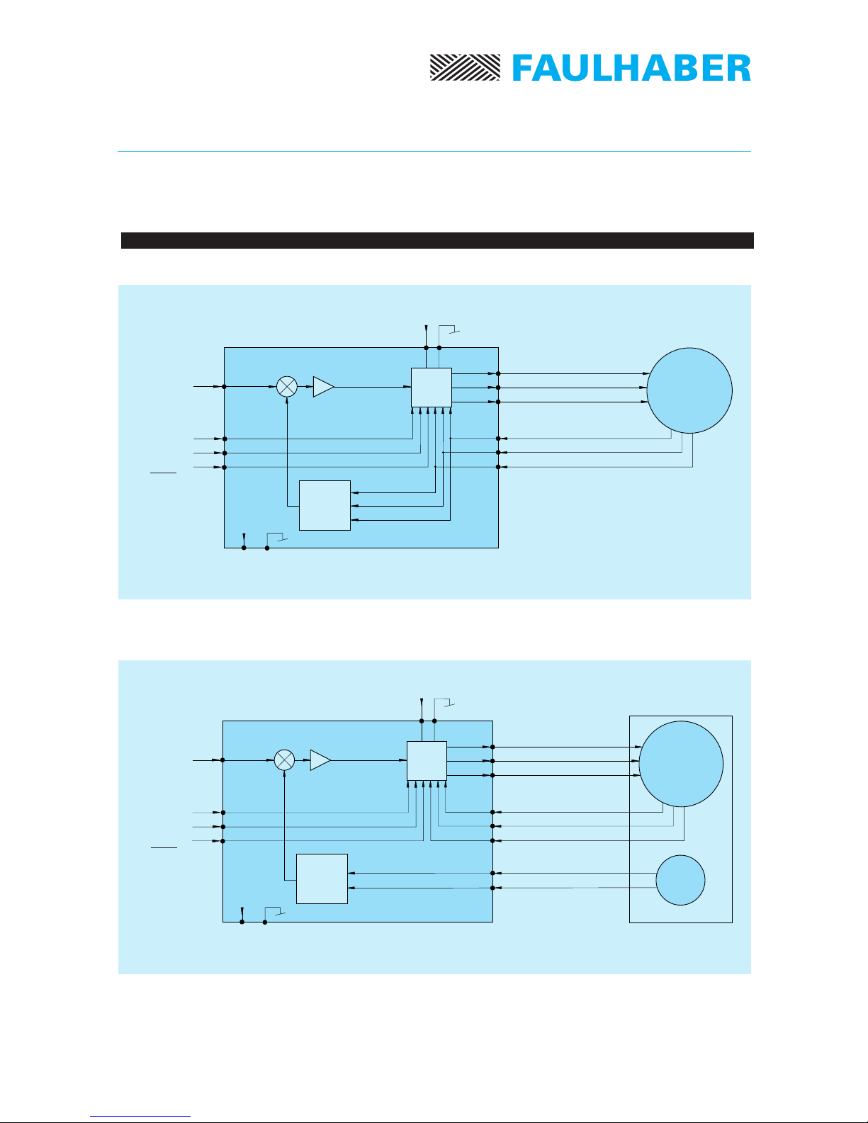
6.7 Basic block diagram for speed control with Hall sensor feedback
6.8 Basic block diagram for speed control with encoder feedback
* Current limiting
GND
Vm
Speed
amplifier BLM
Driver
F/V
converter
Phase
Phase
Phase
Hall sensor
Hall sensor
Hall sensor
Logic
Analog speed
command
Direction
(CW/CCW)
Brake
Enable
Channel
Channel
Encoder
General characteristics
Figure 4
Figure 3
Specifications subject to change without notice
Brushless
DC-Servomotor
1628 ... B
2036 ... B
2444 ... B

6Specifications subject to change without notice
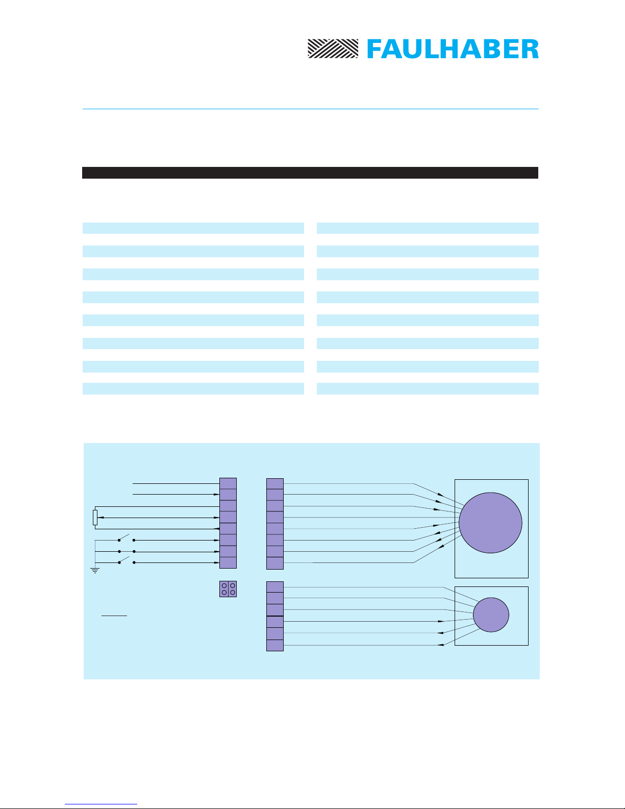
Start-up procedure
7.2 Connection diagram
7.1 Brushless DC-Servomotor with Hall sensor feedback (standard)
7.
Start-up procedure
References
7.2 Connection diagram
7.5 Speed range selection
8
7
6
5
4
3
2
1
1
2
3
4
5
6
7
8
X2
X1
Phase C
Phase B
Phase A
GND Logic
+ V CC
Hall sensor C
Hall sensor B
Hall sensor A
Yellow
Orange
Brown
Black
Red
Grey
Blue
Green
GND
Vm power supply
GND Logic
Analog speed comm.
+ V CC
Enable
Brake
Direction (CW)
Figure 5
Important: Before connecting it is recommended to read chapter 8.
Procedure
- Connect the Servo Amplifier
- Connect Brake Pin 7 with GND Logic Pin 3
- Select R13 resistance
- Power the Servo Amplifier
- Verify the operation
Brushless
DC-Servomotor
1628 ... B
2036 ... B
2444 ... B

7
Servoamplificatore BLD 3502-SH2P
Start-up procedure
References
7.4 Connection diagram
7.6 Speed range selection
7.3 Brushless DC-Servomotor with encoder feedback (optional)
7.4 Connection diagram
Important: Before connecting it is recommended to read chapter 8.
8
7
6
5
4
3
2
1
1
2
3
4
5
6
7
8
X2
X1
1
2
3
4
X3
X4
+ V CC
Channel A
Channel B
GND
Note:
For encoder,
jumpers on X4 must
be removed.
Phase C
Phase B
Phase A
GND Logic
+ V CC
Hall sensor C
Hall sensor B
Hall sensor A
Yellow
Orange
Brown
Black
Red
Grey
Blue
Green
GND
Vm power supply
GND Logic
Analog speed comm.
+ V CC
Enable
Brake
Direction (CW)
Encoder
Figure 6
Procedure
- Connect the Servo Amplifier
- Connect Brake Pin 7 with GND Logic Pin 3
- Connect the encoder
- remove the two jumpers on X4
- Select R13 resistance and C7 capacitor
- Power the Servo Amplifier
- Verify the operation
Specifications subject to change without notice
Brushless
DC-Servomotor
1628 ... B
2036 ... B
2444 ... B
8
References
7.4 Connection diagram
7.6 Speed range selection
7.5 Brushless DC-Servomotor with encoder IE2 – 512
7.6 Connection diagram
Important: Before connecting it is recommended to read chapter 8.
8
7
6
5
4
3
2
1
1
2
3
4
5
6
7
8
X2 X1
1
2
3
4
5
6
X5
X4
–
–
GND
+ V CC
Channel A
Channel B
Note:
For encoder,
jumpers on X4 must
be removed.
Phase C
Phase B
Phase A
GND Logic
+ V CC
Hall sensor C
Hall sensor B
Hall sensor A
Yellow
Orange
Brown
Black
Red
Grey
Blue
Green
GND
Vm power supply
GND Logic
Analog speed comm.
+ V CC
Enable
Brake
Direction (CW)
Encoder
IE2 – 512
Figure 7
Procedure
- Connect the Servo Amplifier
- Connect Brake Pin 7 with GND Logic Pin 3
- Connect the encoder
- remove the two jumpers on X4
- Select R13 resistance and C7 capacitor
- Power the Servo Amplifier
- Verify the operation
Specifications subject to change without notice
Brushless
DC-Servomotor
1628 ... B
2036 ... B
2444 ... B
Start-up procedure

9
Select R13 resistance adapted to the specific application also taking the motor
characteristics into consideration.
Specifications subject to change without notice
Start-up procedure
nmax [rpm] – max. controllable speed (indicatives values)
Gain [rpm/V] – gain factor of Servo Amplifier (tolerance ±15%);
it corresponds to ratio between motor speed
and analog speed command voltage.
7.7 Speed range selection with Hall sensor feedback
nmax [rpm] R13 [kΩ]Gain [rpm/V]
R13 resistance mounted originally: 20 kΩ/ 0,6W / ±1%
C7 capacitor mounted originaly: 10 nF / 100V / ±10%
Application example:
Brushless DC Servomotor type 2444 S 024 B; max. speed of motor requested in this
application nmax = 12 000 rpm.
1. Selection of R13 resistance:
R13 = 36 kΩ; resulting in a max. controllable speed of approx. 15 000 rpm,
slightly higher than 12 000 rpm, which allows a wide speed range operation
of the motor.
Note: A resistance value selected between 36 kΩ(15 000 rpm) and 56 kΩ
(10 000 rpm) would better define the speed range.
2. The gain value allows to calculate the analog input command for a given speed
(speed command = speed / gain).
Example: For 6 000 rpm the speed command is approx 2 V
(speed command = 6 000 / 2 970).
60 000 9,1 12 270
50 000 10 10 250
40 000 14 7 720
30 000 16 6 400
26 500 20 5 300
20 000 27 4 100
15 000 36 2 970
10 000 56 1 970

10
7.8 Speed range selection with encoder feedback
Start-up procedure
7 700 000 / CPR 2,7 0,18 1 490 000 / CPR
3 800 000 / CPR 6,8 0,18 750 000 / CPR
2 100 000 / CPR 6,8 0,47 400 000 / CPR
1 150 000 / CPR 13 0,47 224 000 / CPR
Select R13 resistance and C7 capacitor adapted to the specific application taking both the
motor and encoder characteristics into consideration.
N.B.: The max. motor speed must not exceed the encoder speed range, i.e.:
nmax [rpm] R13 [kΩ]C7 [nF] Gain [rpm/V]
nmax. [rpm] – max. controllable speed;
CPR [-] – number of encoder pulses per revolution;
Gain [rpm/V] – gain factor of servo amplifier; corresponds to
ratio between motor speed and speed command voltage.
fmax [Hz] – max. encoder frequency response.
Specifications subject to change without notice
fmax [Hz] • 60
nmax. [rpm] ≤
CPR [-]

11 Specifications subject to change without notice
Notice of use
8. Notice of use
8.1 Power supply
Any unstabilized DC power supply voltage within the servo amplifier range
(12 V ≤Vm ≤35 V) may be used, although it is advisable to keep this voltage
as low as possible in order to minimize the EMI noise.
Thus the optimum power supply is given by the following relation:
with: R, kE= Terminal resistance (phase to phase) and Back-EMF
constant of the motor.
Imax, nmax = Maximum current and speed reached by the motor in your
specific application.
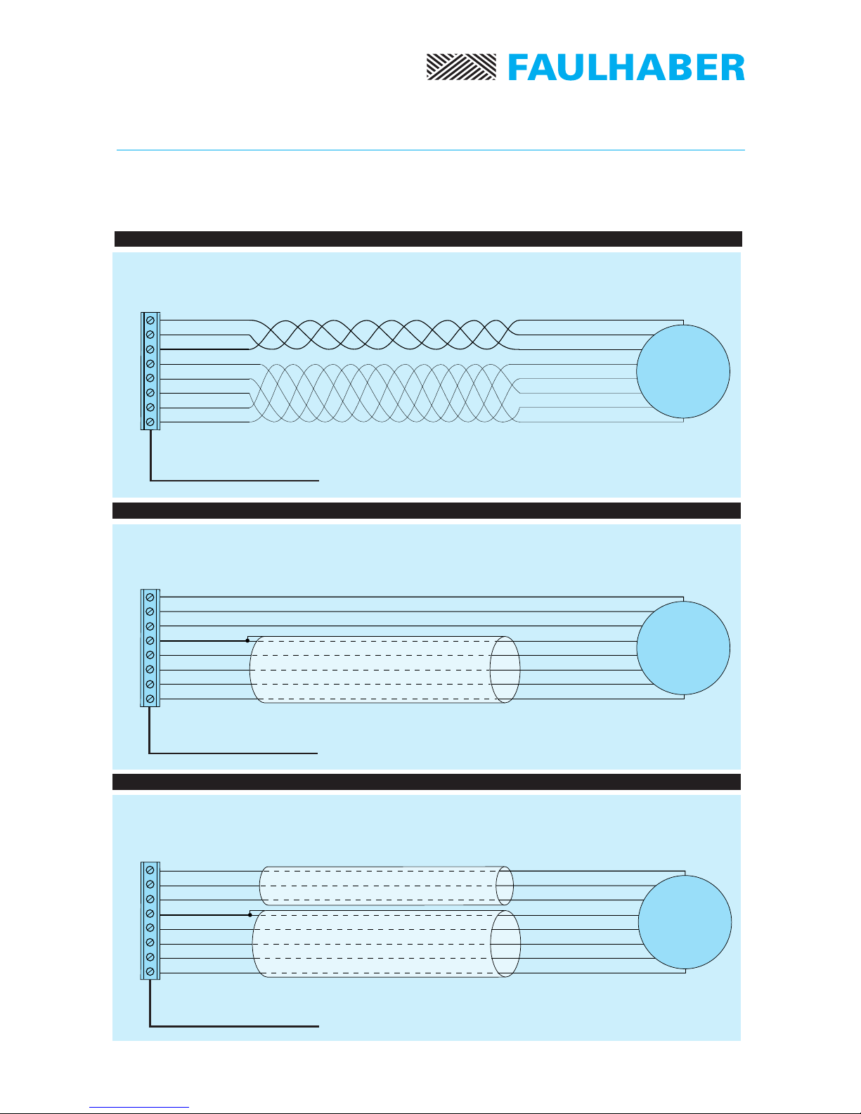
8.2 Wiring
A well known disadvantage of Pulse Width Modulation (PWM) is the large amount of
interferences generated. This has two consequences, namely perturbations to the
environment and self-perturbations.
The EMI is generated by the motor power leads and induced in the Hall sensor wires.
The smooth running of the motor is therefore perturbated and even in some cases, the
motor will not run at all.
In order to reduce the effect of these perturbations, the following basic rules must be
followed:
• Use wires as short as possible;
• Avoid to run signal wires (logic and analog commands, Hall sensor and encoder signals)
in close proximity to power lead wires (power supply and motor phases);
• Connect shielded wires to ground at one end only to avoid ground loops.
Special care should be given to the motor connection. The following table shows the
different solutions:
Vm[V] ≈5 [V] + R [Ω] · Imax [A] + kE[V/rpm] · nmax [rpm]

12 Specifications subject to change without notice
Notice of use
Action To From Self Length
1. No special care no no no 0.3 m
2. Twisted wires (see figure 7) slightly slightly slightly 1.0 m
3. Shielded Hall sensor wires no yes yes 5.0 m
(see figure 8)
4. Shielded Hall sensor and yes yes yes 5.0 m
phases wires (see figure 9)
To: perturbations To environment reduced
From: perturbations From environment reduced
Self: self-perturbations reduced
Length: maximum cable length
Encoder wiring
For wires less than 1.0 m long no particular precautions are required.
For wires longer than 1.0 m the use of shielded cable (as for the Hall sensors)
is recommended.
If wires are longer than 0.3 m, it is recommended to use the following cable sections:
Phase, brushless DC-Servomotors type 1628: 0.5 mm2/ AWG 20;
Phase, brushless DC-Servomotors type 2036: 1.0 mm2/ AWG 18;
Phase, brushless DC-Servomotors type 2444: 1.0 mm2/ AWG 18;
Hall sensors or Encoder for DC-Servomotors type 1628, 2036 and 2444: 0.5 mm2/ AWG 20;
Note: If wires are longer than 5 m please consult us.
13 Specifications subject to change without notice
8
7
6
5
4
3
2
1
8
7
6
5
4
3
2
1
8
7
6
5
4
3
2
1
Twisted wires
Figure 8
Shielded Hall sensor wires
Figure 9
Figure 10
Shielded phase and Hall sensor wires
Connector X1
Brushless
DC-Servomotor
Brushless
DC-Servomotor
Brushless
DC-Servomotor
Connector X1
Connector X1
Phase C
Phase B
Phase A
GND Logic
+ VCC
Hall sensor C
Hall sensor B
Hall sensor A
Phase C
Phase B
Phase A
GND logic
+VCC
Hall sensor C
Hall sensor B
Hall sensor A
Phase C
Phase B
Phase A
GND logic
+ VCC
Hall sensor C
Hall sensor B
Hall sensor A
Yellow
Orange
Brown
Black
Red
Grey
Blue
Green
Yellow
Orange
Brown
Black
Red
Grey
Blue
Green
Yellow
Orange
Brown
Black
Red
Grey
Blue
Green

The FAULHABER Group:
DR. FRITZ FAULHABER
GMBH & CO. KG
Daimlerstraße 23
71101 Schönaich · Germany
Tel.: +49 (0)7031/638-0
Fax: +49 (0)7031/638-100
Email: [email protected]
www.faulhaber.de
MINIMOTOR SA
6980 Croglio · Switzerland
Tel.: +41 (0)91 611 31 00
Fax: +41 (0)91 611 31 10
Email: [email protected]
www.minimotor.ch
MicroMo Electronics, Inc.
14881 Evergreen Avenue
Clearwater · FL 33762-3008 · USA
Phone: +1 (727) 572-0131
Fax: +1 (727) 573-5918
Toll-Free: (800) 807-9166
Email: [email protected]
www.micromo.com
©MINIMOTOR SA
Edition 02.05.2000
Table of contents
Other Faulhaber Amplifier manuals


Popular Amplifier manuals by other brands

D'Amore engine'ring
D'Amore engine'ring E Series owner's manual

Fender
Fender Bassman 300 operating instructions

FM Systems
FM Systems VDA414/C instruction manual

Cary Audio Design
Cary Audio Design CAD-80 Mk-II operating manual

Audiophonic
Audiophonic HP 4000 installation manual

Akai
Akai AA-5800 Service manual

Origin Acoustics
Origin Acoustics A1250 installation manual

Autotek
Autotek SM1600.2 instructions

Nero
Nero STREAM XD2 user guide

Cary Audio Design
Cary Audio Design 7.125 owner's manual

Hughes & Kettner
Hughes & Kettner zenTera DSM-modeling Guitar Amp manual

Flying Mole
Flying Mole CA-S10 owner's manual


