FAXLINK FDS 3500 User manual

LI
FDS 350
0
FAX AND
DATA SWITCH
K
N
USER MANUAL
http://legacy.library.ucsf.edu/tid/ehx08a99/pdf

FAXLINK INTERNATIONAL LT
D
FAXLINK
MODEL
: 350
0
APPROVED
for connection
to
telecom rn uniootion
systems
specified
;
n
he Instructions for
me
st
.13ject to th
e
collations sal aut m the
m
S / 35371
3
/
tvt 50212
8
PEN
: 0
.
5
BATCH NO
'
COUNTRY OF ORIGIN U
.K
.
http://legacy.library.ucsf.edu/tid/ehx08a99/pdf

FOS
3500 - USER MANUA
L
1 .
2
.
3
.
4
.
5
.
INTRODUCTION
5
INDICATOR LIGHTS 6
BASIC OPERATION 7
3
.1
INCOMING CALLS
7
3
.2
OUTGOING CALLS
8
3
.3
POWER FAIL OPERATION
8
UNPACKING AND CONTENTS
9
CONNECTING FDS 3500 FOR USE IN
A
HOME OFFICE
SITUATION
1
0
5
.1
USING FDS 3500
WITH A SINGLE TELEPHON
E
AND A FAX MACHINE (OR A MODEM)
1
0
5
.2
USING FDS 3500
WITH A SINGLE TELEPHONE
,
A FAX MACHINE OR MODEM AND A
N
ANSWERING MACHINE
1
2
5
.3
USING FDS 3500 WITH MORE THAN ON
E
TELEPHONE, A FAX MACHINE OR MODE
M
AND AN ANSWERING MACHINE
15
6.
CONNECTING FDS 3500 FOR USE I
N
AN OFFICE
2
1
6
.1 USING FDS 3500 ON A DIRECT TELEPHON
E
LINE
2
1
7.
CONNECTING FDS 3500 TO A FAX MACHIN
E
AND A MODEM
23
7
.1 OPERATION
2
5
3
http://legacy.library.ucsf.edu/tid/ehx08a99/pdf

8
.
ANSWERING MACHINE MODE (AMM
)
8 .1
INCOMING CALLS WITH AN ANSWERING
26
MACHINE
2
7
8
.2
AMM CONTROLS 28
9
.
RING COUNTING
30
10
.
ADDITIONAL INFORMATION ON 'TONE
'
SWITCHING
3
2
10
.1
WHEN TO USE 'TONE' SWITCHING
3
2
11
.
EQUIPMENT CONSIDERATIONS
3 3
11 .1
ANSWERING MACHINES
3
3
11
.2 FAX MACHINES
3
3
11
.3
LINE LOADING
34
11
.4
MODEMS
34
12
.
SUMMARY OF SELECTOR SWITCHES 3
5
13
.
IMPORTANT INFORMATION
36
4
http://legacy.library.ucsf.edu/tid/ehx08a99/pdf
1
. INTRODUCTIO
N
Your FDS 3500 is a sophisticated automatic switching device which wil
l
enable you to connect your fax machine or modem onto your existin
g
telephone line
. Your FDS 3500 has been designed to meet your growin
g
requirements and it will give many years of trouble free service
.
WE STRONGLY RECOMMEND THAT YOU REA
D
SECTIONS 1,2 AND 3 OF THIS USER GUID
E
BEFORE INSTALLING YOUR FDS 3500
.
FDS 3500 is the only device of it's type that will give you telephon
e
priority It has been designed to monitor all of your telephone calls an
d
transfer fax calls to your fax machine under certain conditions
. For th
e
majority of your telephone calls, voice calls
. FDS 3500 does not act a
s
a switch, it simply sits in the background and monitors the line
.
Your FDS 3500 will detect the calling tones (known as CNG) which ar
e
transmitted by most fax machines. On detecting these calling tones
,
FDS 3500 will transfer these fax calls to your fax machine
.
FDS 3500 will also switch calls to your fax machine under certain othe
r
conditions, the details of which are contained in the relevant section
s
of this user guide
.
This manual, together with the Quick Reference Guide, has bee
n
designed to take you through the installation of your FDS 3500 step b
y
step
. You will not need any specialist knowledge or tools
. Simply refe
r
to the section of this user guide that is closest to the description of you
r
particular installation and follow the instructions
.
NOTE
:
On
the rear
of your FDS 35010 you will find six smal
l
switches
. These switches have been preset at tile fectov
y
to suit the majority of users
. It is extremely simple to alte
r
the position of these switches to suit your particula
r
requirements
. Please consult Section 12 of this user guid
e
before altering the position of these switches
.
5
http://legacy.library.ucsf.edu/tid/ehx08a99/pdf
2
. INDICATOR LIGHT
S
Your FDS 3500
Is
equipped with two indicator lights which will allow yo
u
to monitor the operation of your FDS 3500
.
The indicator lights are marked LINE 1 and LINE
2
The indicator marked LINE 1 will illuminate whenever a telephone o
r
answering machine plugged into LINE 1 or LINE 3 is being used
,
whether on an incoming or outgoing cal
l
The Indictor marked LINE 2 will illuminate whenever your fax or mode
m
is being used
.
When your telephone(s) ring, answer as normal
. The indicator marke
d
LINE 1 will illuminate
. If the call is from a fax machine, as FDS 350
0
transfersthe call to your fax machine the LINE 1 indicator will go cut an
d
LINE 2Indicator will come on
. At the end of the call the relevant ina
:cato
r
light will go out
. indicating that your FDS 3500 has completed its cycl
e
and is now ready for the next call
.
The indicator lights will also allow you to ensure that your FDS 3500 i
s
powered correctly
. After installing your FDS 3500 turn the mains suppl
y
on
. Lift the telephone connected to LINE 1 or LINE 3 as
If
you wer
e
making an outgoing telephone call
. The indicator marked LINE
1
shoul
d
light up
. Then attempt to transmit a fax, and the indicator markea LIN
E
2 should illuminat
e
If during this testing procedure the lights do not illuminate please chec
k
that the power is turned on and that the leads are correctly plugged int
o
the back of your FDS 350
0
If in the unlikely event that
. after checking the leads, the lights still tai
l
to illuminate please contact our Technical Hotline service for furthe
r
advice
6
http://legacy.library.ucsf.edu/tid/ehx08a99/pdf

3
. BASIC OPERATIO
N
3
.1 INCOMING CALL
S
As FDS 3500 gives priority to your telephone calls, ALL of th
e
telephones connected to your telephone line will ring on every incomin
g
call, regardless of whether the call
Is
from a telephone or a fax machine
.
When your telephone(s) ring, answer the call In the normal way
. Whe
n
it is a person calling just carry an talking as normal
. If the call
Is
from
a
fax machine you will usually hear a high pitched tone every 3 second
s
On hearing these tones you can take one of two actions, depending o
n
your installation and equipment
.
a)
If the telephone is connected into your FDS 3500 and switch 2 i
s
In the 'up
'
position, simply hang up the telephone on hearin
g
these tones
.
b) If the telephone is not directly connected to FDS 3500, but is o
n
an extension, simply dial `10'
.
NOTE
:
You can change the carte' code iroM
'
10' to
'
1
'0* tf you wis
h
by changing the position of switch I
On
the rear of you
r
FD$ 3500
.
If you do not answer the telephone within eight rings FDS 350
0
will automatically transfer the call to your fax machine This is a fail saf
e
device to ensure that you can still receive faxes when you are out I
f
eight rings is too quick you can alter this ring counting by changing th
e
positions of switches 3 and
4
.
Please consult Section 9 of this use
r
guide
.
7
http://legacy.library.ucsf.edu/tid/ehx08a99/pdf

If the call is from someone wishing to send you a fax, simply tell the
m
to 'Start their machine when they hear the fax tones"
. You must then dia
l
'10
'
. FDS 3500 will then activate your fax machine
.
NM
;
Pee
tsre€ aty answer
tg
machine
does
not hav
e
the earn* ring Ctt f as y wr F05 3500
. Sea Section
8
for more inform atiort on
ring
renting and Sections 8 an
d
11
.1
foray onsweling machin
e
3
.2 OUTGOING CALL
S
Making outgoing calls is unaffected by the installation of FDS 3500, Yo
u
proceed as you normally would, remembering that you cannot make fa
x
and telephone calls at the same tim
e
3
.3
POWER FAIL OPERATIO
N
Should you experience a power cut or power failure, your telephone(s
)
will continue to work as normal even if they are connected to FOS 3500
.
Your fax machine and answering machine require mains electricity an
d
will not work
.
FDS 3500 will automatically reset itself when power is restore
d
8
http://legacy.library.ucsf.edu/tid/ehx08a99/pdf

4
. UNPACKING AND CONTENT
S
Your FOS 3500 box will contain the following items
.
1 x FOS 350
0
1 x Telephone line cor
d
3 x Adaptor socket
s
1 x Power Adapto
r
1
x User Guid
e
1 x Quick Reference Guid
e
1
x Warranty Registration Documen
t
IMPORTAN
T
Only use the adaptors, lead
and
power supply supplie
d
with
your FOS 3500 unit
. If you do not use the correct
lead
s
ycurFDS 3500 may not work properly and damagecoul
d
be caused to either your FOS 35000 or to equ men
t
connected to
i
t
Features of the FDS 3500 showing initia
l
connecting up arrangement
s
Selector Switc
h
Power Suppl
y
Unit Inpu
t
Jack Socket
Lines 1-
3
9
http://legacy.library.ucsf.edu/tid/ehx08a99/pdf
5
. CONNECTING FDS 3500 FOR USE IN A HOM
E
OFFICE SITUATIO
N
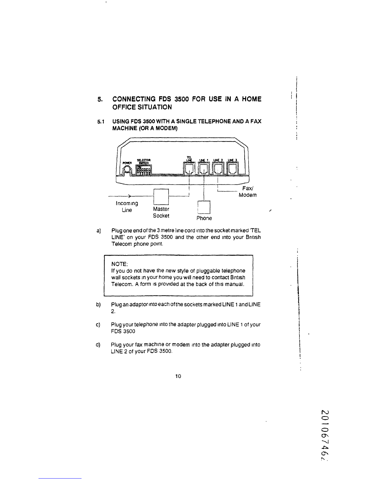
5
.1 USING FDS 3500 WITH A SINGLE TELEPHONE AND A FA
X
MACHINE (OR A MODEM
)
a) Plug one end of the 3 metre line cord into the socket marked TE
L
LINE
'
on your FDS 3500 and the other end into your Britis
h
Telecom phone point
.
NOTE
:
If you do not have the new style of pluggable telephon
e
wall sockets In your home you will need to contact Britis h
Telecom . A form
Is
provided at the back of this manual
,
b)
Plug an adaptor into each of the sockets marked LINE 1 and LIN
E
2
.
c)
Plug your telephone into the adapter plugged into LINE
1
of you
r
FDS 350
0
d)
Plug your fax machine or modem into the adapter plugged int
o
LINE 2 of your FOS 3500
.
>
j
Incomin
g
Line
Maste
r
Socket
Phon
e
10
http://legacy.library.ucsf.edu/tid/ehx08a99/pdf
Table of contents


