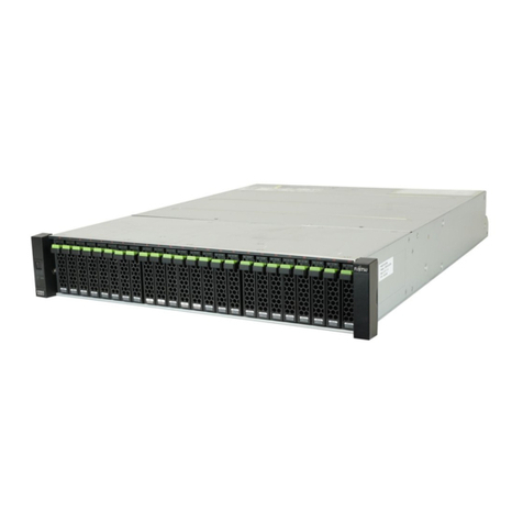
FEB HV5120-S Series User manual

High Voltage Energy Storage System
Battery HV5120-S Series Product Manual

2 / 23
This manual introduces HV5120-S from FEB. Please read this manual before you install the battery and follow the
instruction carefully during installation process. Please contact FEB immediately for advice and clarification if you
have any question.
Contents
Catalogue
1.Symbol Description................................................................................................................................................................3
2.Safety Precautions .................................................................................................................................................................4
2.1 Before Connecting................................................................................................................................................................4
2.2 In Using ................................................................................................................................................................................4
3.Introduction ...........................................................................................................................................................................5
3.1 Features.................................................................................................................................................................................5
3.2 Specification .........................................................................................................................................................................6
3.3 Equipment interface instruction............................................................................................................................................7
4.Safe Handling of Lithium-iron ESS Batteries Guide........................................................................................................12
4.1 Solution Diagram................................................................................................................................................................12
4.2 Danger Label ......................................................................................................................................................................12
4.3 Tool................................................................................................................................................................................... 12
4.4 Safety Gear .........................................................................................................................................................................13
5.Installation and operation...................................................................................................................................................14
5.1 Package items .....................................................................................................................................................................14
5.2 Installation Location ...........................................................................................................................................................15
5.3 Installation Direction ..........................................................................................................................................................15
5.4 Installation Steps.................................................................................................................................................................16
5.5 System turns on...................................................................................................................................................................19
5.6 System turns off..................................................................................................................................................................20
6.Emergency Situations.........................................................................................................................................................20
6.1 Battery Leakage..................................................................................................................................................................20
6.2 On Fire................................................................................................................................................................................20
6.3 Wet Batteries ......................................................................................................................................................................20
6.4 Damaged Batteries..............................................................................................................................................................20
7.Remarks................................................................................................................................................................................21
7.1 Recycle and Disposal..........................................................................................................................................................21
7.2 Maintenance........................................................................................................................................................................21
7.3 Declaration of conformity...................................................................................................................................................21

3 / 23
1. Symbol Description
Do not place near open fire or flammable materials.
A potential hazard exists when the equipment is working. Wear
personal protective equipment during operation.
Warning electric shock.
Power off the equipment before any operation.
Grounding: indicate PE cable connection position.
Do not place in areas accessible to children.
Keep the battery away from open fire or ignition sources.
Read the product and operation manual before operating the battery
system.
Label for Waste Electrical and Electronic Equipment (WEEE)
Directive (2012/19/EU)
The certificate label for CE.
Recycle label.

4 / 23
2. Safety Precautions
Alert
1) It is important and necessary to read the user manual carefully (and attachment) before installing or using
battery. Failure to do so or to follow any instruction or warning in this document can result in electrical
shock, serious injury, and death, or damage battery, potentially rendering it unusable.
2) When battery is stored for a long time, it is required to charge once every 6 months, and the SOC should be
no less than 85%.
3) After battery module cannot be discharged, it needs to be recharged within 12h.
4) Do not connect power terminal reversely.
5) All power supplies must be disconnected during maintenance.
6) Please contact the supplier within 24 hours if there is something abnormal.
7) Do not use any liquid to clean the battery.
8) Do not expose battery to flammable or irritating chemicals or vapor.
9) Do not paint any part of battery, including any internal or external components.
10) Do not connect battery with PV solar wiring directly.
11) Do not install or use this product beyond provisions of the manual.
12) Direct or indirect damages caused by the above reasons are not covered by warranty claim.
Warning
2.1 Before Connecting
1) Please check the external packaging condition before unpacking. If it is damaged, contact corresponding
local retailer.
2) After unpacking, please check the products and spare parts according to spare parts list. If the product is
damaged or missing, please contact your local retailer.
3) Connect to specified matching inverter.
4) Before installation, be sure to cut off the grid power and make sure battery is in turned-offmode.
5) It is prohibited to connect the battery and AC power directly.
6) Embedded BMS in the battery is designed for 24VDC.
7) All electrical wiring must be connected in accordance with local regulations.
8) Please ensure that electrical performance of battery system is compatible with theequipment.
9) The installation onsite shall be equipped with fire-fighting facilities that meet relevant requirements, such
as fire sand, dry powder fire extinguisher, etc.
2.2 In Using
1) If battery system needs to be moved or repaired, power must be cut off and battery is completely shut
down.
2) It is prohibited to connect battery with different types of battery.

5 / 23
3) Do not connect battery to faulty inverter.
4) In case of fire, only dry powder fire extinguisher can be used, liquid fire extinguishers are
prohibited
5) Do not open, repair or disassemble the battery except Far East Battery personnel or other authorized
personnel. The company shall not bear any liability or responsibility caused by violation of any safety
operation or design standard, production standard, equipment safety standards or any other standards or
requirements.
3.Introduction
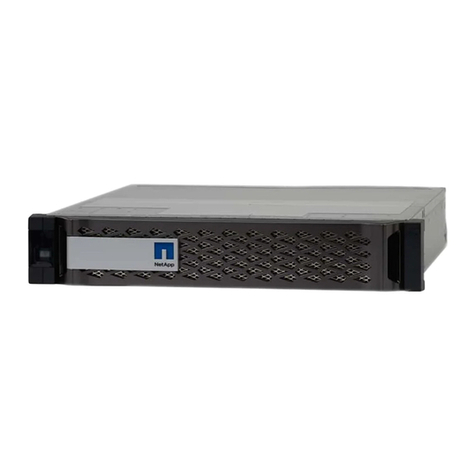
HV5120-S energy storage system battery is a new energy storage product developed and produced by
FEB, which can provide reliable power supply for all kinds of equipment or systems.
Figure 3-1
3.1 Features
1) Built-in soft-start function to reduce current impact.
2) When multiple modules are series connected, module addresses are set automatically.
3) Support for upgrading the battery module from the upper controller through CAN communication.
4) The module is non-toxic, non-polluting and environmentallyfriendly.
5) Cathode material is made from LiFePO4 with safety performance and long cyclelife.
6) Battery management system (BMS) has protection functions including over- discharge, over-charge,
over-current and high/low temperature.
7) The system can automatically manage charge and discharge state and balance voltage of each cell.
8) Flexible configuration, multiple battery modules can be connected to expand capacity and power.
9) Adopted self-cooling mode rapidly reduced system entire noise
10) The module has less self-discharge, up to 6 months without charging it on shelf, no memory
effect, excellent performance of shallow charge and discharge
Functions
Protection and Alarm
Management and monitor
Charge/Discharge End
Cell Balance

6 / 23
Overvoltage Charging Protection
Intelligent Charge Model
Under Voltage Discharging Protection
Charge/Discharge Current Limit
Charge/Discharge Overcurrent Protection
Capacity Retention Calculate
High/Low Temperature Protection
Soft start
Short Circuit Protection
History Record
3.2 Specification
Parameters
No.
Items
Specification
1
Product Name
Rechargeable Lithium Iron Phosphate Module
2
Module Model
HV5120-S1
3
Battery Type
LFP 1P32S
4
Nominal Capacity
5.12kWh
5
Usable Capacity
4.86kWh(95% DOD)
6
Nominal Voltage
102.4V
7
Working Voltage
91.2~115.2V
8
Charging Voltage
112V
9
Max. Charge Current
25A
10
Max. Discharge Current
40A
11
Communication
RS485 , CAN
12
Storage Temperature
-20℃~50℃(0~45℃(Recommended))
13
Storage Humidity
≤85%(RH)
14
Working Temperature
Charging:0℃~50℃
Discharging:-20℃~50℃
15
Working Humidity
≤95%(RH)No Condensation
16
Working Altitude
≤2000m
17
Ingress Protection
IP55
18
Protective Class
I
19
Weight
~45kg
20
Dimension
636mm*330mm*188mm
21
Design Life
15 Years(25℃)
22
Cycle Life
>6000(25℃),60% EOL
23
Scalability
Module: Max. 8S
24
Certification
IEC62619, IEC63056,
CE EMC, UN38.3
Dimensions

7 / 23
Figure 3-2
3.3 Equipment interface instruction
Figure 3-3

8 / 23
Figure 3-4
Turn on: When battery is dormant, press the START button to start the battery module.
Black start: Press and hold the button for 10s to turn on the battery for black start.
Blue LED lighting to show the battery system is running or having alarm.
Status
Mode
Run/Alarm
Remark
Power off
Power off
Light is off
Run
Standby/Charge/Discharge
Light is on
Alarm
Level ⅠAlarm
System can run, but there will be alarm tips
Level ⅡAlarm
System will stop, and check the problem
Note
Description of indicator light
The indicator light is off.
The indicator light is on
The indicator light is flashing. Duration of indicatoron is 0.25s, Duration of indicator off is 3.75s.
The indicator light is flashing. Duration of indicatoron is 0.5s, Duration of indicator off is 1.5s.

9 / 23
Green LEDs are used to show the battery’s remaining capacity.
State
Charging/Discharging
Capacity Indicator LED
L5
L4
L3
L2
L1
SOC
0~20%
20~40%
40~60%
60~80%
80~95%
95~100%
Note
The SOC indicator light is off.
The SOC indicator light is on.
The SOC indicator light is flashing, Duration of indicator on is 0.5s, Duration of indicatoroff is 0.5s.
When you rotate the Isolating Switch to ON position, Positive Power Terminal will connect with the HV+
battery contactor and Negative Power Terminal will connect with the battery HV-, on the other hand, when
Isolating Switch is at OFF position both connection will off.
Figure 3-5
Power cable terminals: there are two pairs of terminals with same function, one
connects to equipment, the other one paralleling to other battery module for
capacity expanding.
For power cables uses water-proofed connectors. Must keep pressing this Lock
Button while pulling out the power plug.
Figure 3-6

10 / 23
Be used to communicate with inverter or upper battery.
Figure 3-7
RJ45 Socket
RS485-1: Communication with PCS by RS485
CAN3: Communication with PCS by CAN
CAN1: Master/slave communication channel
CAN communication port with upper computer or display monitor.
Figure 3-8
Pin
Definition
1
RS485-1A
2
RS485-1B
3
Undefined
4
CAN3-H
5
CAN3-L
6
Undefined
7
CAN1-H
8
CAN1-L
COM

11 / 23
RJ45 Socket
Pin
Definition
1
24V-
2
ADDR_DO
3
Undefined
4
Undefined
5
Undefined
6
Undefined
7
CAN2H
8
CAN2L
ADDR_DO: Output signal for Master BCU to arrange the address.
24V- : 24V- signal
CAN communication: CAN bus for each rack and upper computer or display monitor. (CAN2H CAH2L).
For battery debug usage.
Figure 3-9
RJ45 Socket
Pin
Definition
1
24V-
2
ADDR_DI
3
Master Address DI
4
RS485-2B
5
RS485-2A
6
Undefined
7
24V-
8
24V+

12 / 23
24V: DC Input (Pin8 connect with 24V+, Pin1&pin7 connect with 24V-).
Master Address DI: For Master rack to arrange the address.
RS485-2: communication: RS485 for each rack and upper computer or display monitor (RS485-2A RS485-2B).
4. Safe Handling of Lithium-iron ESS Batteries Guide
4.1 Solution Diagram
Figure 4-1
4.2 Danger Label
Figure 4-2
4.3 Tool
Wire Cutter Modular Crimping Plier Screwdriver Electric drill
Note

13 / 23
Properly use insulated tools to prevent accidental electric shock or short circuits. If tools are not insulated,
cover the entire exposed metal surfaces of available tools with electrical tape except their tips.
4.4 Safety Gear
It is recommended to wear the following safety gear when dealing with battery pack.
Insulated Gloves
Safety Goggles
Safety Shoes

14 / 23
5.Installation and operation
5.1 Package items
Unpacking and check the Package items
1) For battery module package:
⚫Battery Module
2) For packing box of high voltage box:
NOTE: Power and communication cables connect to inverter belongs to the packing box of high voltage box.
⚫2 * 2000mm 6AWG power cables
⚫1 * 3000mm RJ45 communication cable
⚫1 * 3000mm 10AWG grounding cable
Figure 5-1

15 / 23
5.2 Installation Location
Make sure that installation location should meet the following condition:
1)
The area should be completely water-proof.
2)
The floor should be flat and level.
3)
No flammable or explosive materials.
4)
The ambient temperature is within the range from 0°Cto 45°C.
5)
The temperature and humidity are maintained at a constantlevel.
6)
There is just a little dust and dirt in thearea.
7)
The distance from heat source should be more than 2meters.
8)
The distance from air outlet of inverter is more than 0.5meters.
9)
Installation areas should avoid direct sunlight.
10)
No forced ventilation requirement for battery module, but please avoid installing in a closed area.
Ventilation shall avoid high salinity ≤ 30%, humidity ≤ 85% and ambient temperature of 0 ~ 45 ℃.
5.3 Installation Direction
Warning
Upside down
Sidelong
Sidelong

16 / 23
NOT allowed
NOT allowed
NOT allowed
Figure 5-2
5.4 Installation Steps
Warning
1)
Follow local electric safety and installation policy, a suitable breaker between battery system and inverter
is required.
2)
All installation and operation must follow local electric standard and requirements.
3)
When battery modules are paralleled, the system should be powered off before installation operation

17 / 23
1. Install the brackets to the base of the battery rack using 2 pcs M4*10 socket head cap screws with locking
torque of 2.5N•m.
Figure 5-3
2. Install the brackets to the HV Box of the battery rack using 2 pcs M4*10 socket head cap screws with
locking torque of2.5N•m.
Figure 5-4
3. Place the base against the wall and mark the position of mounting holes on the wall. Remove the base and
drill holes using an electric drill. The electric drill must with a dust cover to prevent dust from falling off.
Figure 5-5

18 / 23
Figure 5-6
4. Place the base against the wall and fix the base to the wall with position of mounting holes on the wall
with 2 pcs M6 expansion screws by 8N•m.
Figure 5-7
5. Then lay the battery module one by one on the base, and fix all the M4*8 sunk screws on the left side and right
side(each module have 4 fixed point)by 2N•m.
Figure 5-8

19 / 23
6. Place the HV box on the top of the module and mark the position of mounting holes on the wall. Remove the
HV box and put a dust cover over the top of the module and then drill holes using an electric drill to prevent dust
from falling off. Place the HV box back and fix the base to the wall with position of mounting holes on the wall
with 2 pcs M6 expansion screws by 8N•m.
Figure 5-9
7. Connect the ground cable, power cable and communication cable between PCS and battery rack .
Figure 5-10
5.5 System turns on
Warning: Double check all the power cables and communication cables. Make sure the voltage of the inverter/PCS
is same level with the battery system before connection. Check all the power switches are OFF.
System turns on step:
1) Check all cables are connected correctly. Check grounding is connected.
2) If necessary, turn on the switch at inverter`s battery side or between inverter and battery. If possible, turn on
AC or PV power source to wake up inverter.
3) Open protect cover of Power switch. And turn on power switch.
4) Switch all the battery racks’Isolating Switch to on position.
5) Press the battery STARTbutton in turn, turn on the START metal button of the slave battery firstly, and
finally turn on the START button of the master battery (1 master battery rack and 7 slave battery racks at most
can be configured).
6) If no alarm ,the battery system will be ready for charging and discharge with PCS

20 / 23
5.6 System turns off
When failure or before service, must turn the battery storage system off:
1) Turn off inverter or power supply on DC side.
2) Turn off the switch between PCS and battery system.
3) Switch Isolating Switch to off position. (Switch off the slave battery firstly, finally switch off the master
battery)
Note
1) One battery system shall just have one master, all the others are slaves. (The one on the extreme
side connectedto inverter is the masterbattery.)
2) It is forbidden to switch off the Isolating Switch during charging and discharging.
6.Emergency Situations
6.1 Battery Leakage
If the battery pack leaks electrolyte, avoid contact with the leaking liquid or gas. If one is exposed to the
leaked substance, immediately perform the actions described below
1) Inhalation: Evacuate contaminated area and seek medical aid.
2) Contact with eyes: Rinse eyes with flowing water for 15 minutes and seek medical aid.
3) Contact with skin: Wash affected area thoroughly with soap water and seek medical aid.
Ingestion: Induce vomiting and seek medical aid.
6.2 On Fire
NO WATER!
Only dry powder fire or carbon dioxide extinguisher can be used; if possible, move the battery module to a
safe area before it catches fire.
6.3 Wet Batteries
If the module is wet or submerged in water, do not let people access it, then contact FAR EAST BATTERY or an
authorized dealer for technical support. Cut off all power switch on inverter side.
6.4 Damaged Batteries
Damaged batteries are dangerous and must be handled with utmost care. They are not fit for use and may pose
a danger to people or property. If the module seems to be damaged, pack it in its original container, then return
it to authorized dealer.
Warning
Damaged batteries may leak electrolyte or produce flammable gas.
Table of contents
