FEC FEC-150 User manual
User Manual
FEC-150
Thermal Printer
Rev. 1.00
http://www.Firich.com.tw

Rev. 1.00 - 2 -
FEC-150
■Safety Warning
Proper use of this product can prevent hazardous or physical harm. Make sure all
following instructions are followed when using this product.
Warning
Violation of following instructions may cause serious injure or risk of life.
Keep it in plastic bag and keep out of reach
of children.
• Plastic bag capped on the children’s heads may
cause hazard.
Please use the adapter provided.
•Other adapter may cause a danger.
Do not bend the power cord or put heavy things on i
t, ensuring no damage to the cord.
• May cause a fire.
Do not insert or remove the plug with wet hands.
• May case electric shock.
Do not pull the power cord when unplugging.
• Power cord may cause a fire or malfunction resulting in
harms.
Do not connect several plugs into a socket.
•High temperature or fire may cause a danger.
•Use the plug before wiping it in case of contamination of
foreign material or water.
•Do not insert the plug into a socket with loosened slots.
•Use approved multi-slots socket.
Prohibit
Prohibit
Prohibit
Prohibit
Prohibit
Prohibit
ONLY SUPPLIED ADAPTER

Rev. 1.00 - 3 -
FEC-150
Caution
Violation of following instructions may cause slight injure or damage to
the product.
Do not use a malfunctioned product that may cause
a fire or electric shock.
• Power off the printer, remove the plug from the socket and co
ntact the distributor.
Note that no water or foreign material is allowed in
the printer body.
•Power off the printer, unplug from the socket and contact the
distributor in case that there is water or foreign material in
the body.
Use the approved product. Do not disassemble,
repair or alter the product.
• Consult the distributor for damage to the product.
•Do not touch the sharp blade on the auto cutter.
Install the product in a stable place.
• Falling down may cause damage to the product or
injure.
Keep the drier out of reach of children.
• Eating the drier may result in serious harm to health.
Power off and take following actions immediately in
case of the product producing smoke, or strange
smell or sound.
• Power off the printer and remove the plug from the socket
immediately in case of exceptional situation.
• Make sure whether there is smoke, and take it to distributor f
or repair.
Prohibit
Plug Prohibit Prohibit
Prohibit
Socket Prohibit
No disassembling
PRINTER
PRINTER
PRINTER
PRINTER
DEALER
PRINTER

Rev. 1.00 - 4 -
FEC-150
Copyright FIRICH
(C) Copyright CIRICH Co., Ltd.
All rights reserved
Partial or total duplication, reproduction or translation of the User Manual and product or
convert to any electronic media or readable form without prior written permission is
prohibited. The errors related to printing or technology in the User Manual and product are
subject to change without prior notice.
FIRICH LOGO is the registered trademark of FIRICH.
For the distributor and user’s attention, this machine has the same model as the one
commercially registered EMI (electromagnetic interference). If you sell or purchase by
mistake, please change back into the household type.
We at FIRICH maintain ongoing efforts to enhance and upgrade the functions and quality
of all our products. In following, product specifications and/or user manual content may be
changed without prior notice.
■WEEE (Waste Electrical and Electric Equipment)
The product marked with this symbol or relevant text indicates that the product
cannot be discarded with other family wastes at the end of its life. Please
separately dispose of it from other wastes to avoid any harm to the environment
and human being. Observe the Recycling Policy to make full use of the limited
resource. The household user can contact the distributor or local service office
for any information about proper disposal methods and premises. The commercial user
can contact the supplier or dispose as per the terms provided in the Purchase Contract.
This product cannot be disposed with other commercial wastes.
■Symbol material: PET
Rev. 1.00 - 5 -
FEC-150
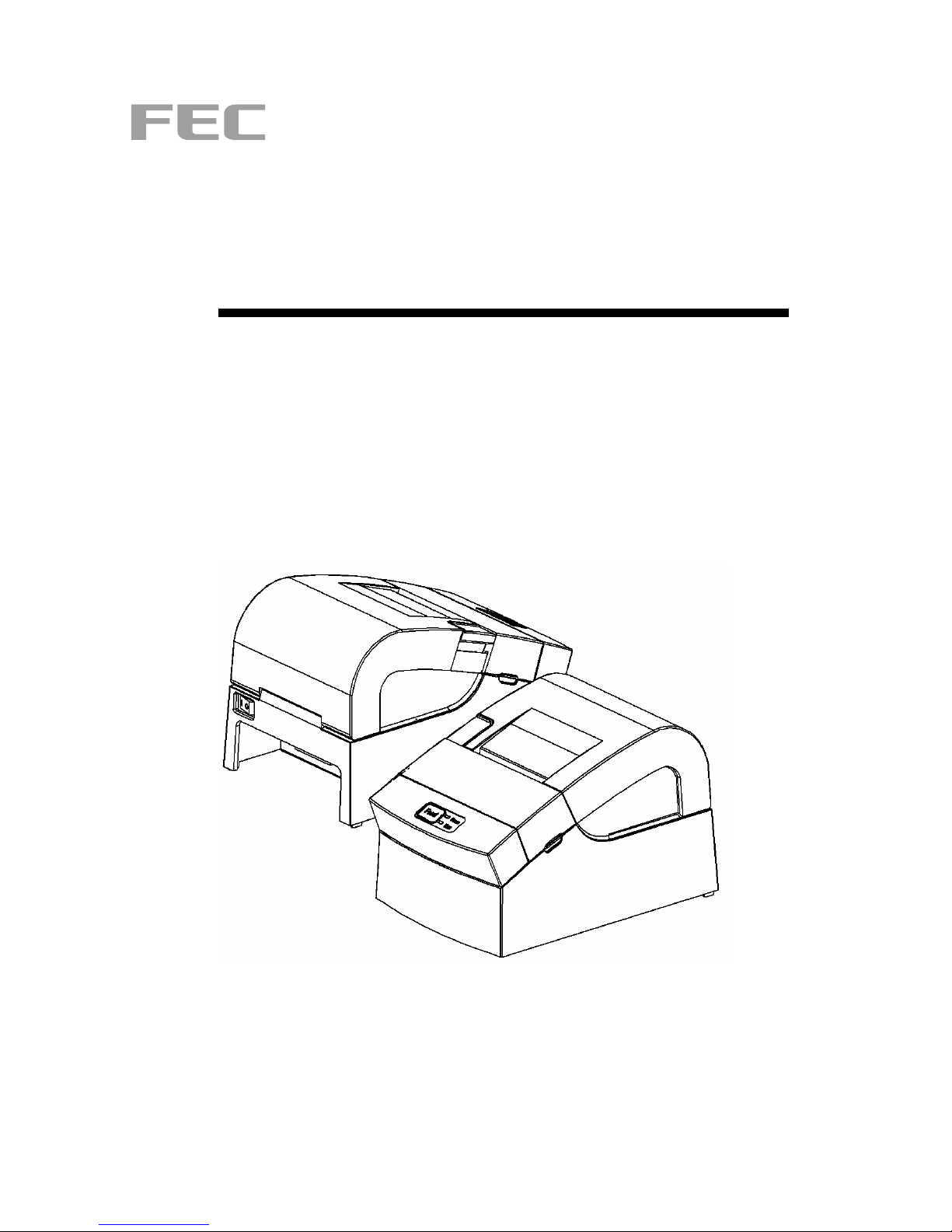
■Introduction
Assembly Name
(1) COVER PAPER
(2) ROLLER ASS’Y
(3) PAPER
(4) COVER CUTTER
(5) COVER FUCNTION
(6) CASE MAIN
(7) CASE LOWER
(8) COMMUNICATION PORT
- P ARALLEL/SERIAL
(9) CASH DRAWER (RJ-11)
(10)USBCOMMUNICATION
Rear
FEC-150P/R,FEC-150U The printer is a banking peripheral device and can be used with
ECR, POS etc.
Its main features are shown as follows:
1. High speed printing;
2. Thermal printing with low noise;
3. RS-232 series interface(FEC-150R), IEEE1284 parallel interface(FEC-150P),
USB2.0 interface(FEC-150U).
4. Reception of data is possible via Data buffer, even in printing process.
5. The Document Image Processing button enables selection of different printing density.
Please read this User Manual carefully before using FEC-150P/R, FEC-150U.
※Note
The socket is required near the machine for use.
FEC-150P/R FEC-150U
Rear
(8) (9) (10) (9)
(2)
(1)
(3)
(4)
(5)
(6)
(7)

Rev. 1.00 - 6 -
FEC-150
■ Table of Contents
1. Installation and basic operations ·················································································7
1-1 Unpacking ·····················································································································7
1-2 Installation Site ··············································································································7
1-3 Operation Panel ············································································································8
2. Connection ·····················································································································9
2-1 AC Adapter Connection ·································································································9
2-2 Interface Connection ···································································································10
2-2-1 FEC-150R Serial Interface ····················································································11
2-2-2 FEC-150P Parallel Interface··················································································12
2-2-3 FEC-150U USB Interface······················································································12
2-2-4 Cash Drawer Cable Connection (Option)······························································13
3. DIP Switch Setting ·······································································································14
3-1 Setting the DIP Switches·····························································································15
3-1-1 Setting the DIP switch (RS-232C Serial Interface) ················································15
3-1-2 Setting the DIP switch (IEEE1284 Parallel, USB2.0 Interface)······························15
3-2 Setting the Memory Switches······················································································15
4. Paper Loading··············································································································18
5. Sample Test··················································································································19
6. Hexadecimal Dumping ································································································20
7. Specification ················································································································21
8. WINDOWS Driver Setting ····························································································22
8-1 Serial (RS-232C) Interface Model Windows Driver Setting ·········································22
8-2 Parallel (IEEE1284) Interface Windows Driver Setting················································23
8-3 USB2.0 Interface Model Windows Driver Setting ························································23
9. Control Command List ································································································24
10. Summary of Control Command················································································25

Rev. 1.00 - 7 -
FEC-150
1. Installation and basic operations
1-1 Unpacking
Make sure all following items are available. Please contact the distributor immediately in
case of loss or damage.
1-2 Installation Site
Keep the product away from the high temperature or direct sunlight.
Do not place it at the place full of moisture.
Keep it at a stable place and away from shock.
Leave enough space for the printer for convenient use.
Printer
Paper User Manual
Power cord
CD
Cable interface
USB, Serial, parallel cable

Rev. 1.00 - 8 -
FEC-150
1-3 Operation Panel
The Panel consists of one button and two indicators.
Button
FEED
To print one paper, press the FEED button.
To continuously print, press and hold the FEED button.
Indicator
The indicator indicates the state of the printer.
POWER (green)
The indicator lights when the printer powers on.
ERROR (red)
The indicator lights when the paper is used out, or the printer is in idle,
or the cover opens.

Rev. 1.00 - 9 -
FEC-150
2. Connection
2-1 AC Adapter Connection
It is required to used the power cord and adapter accompanied with the printer.
※Warning
Improper power unit may cause a fire or hazard.
※Note
1. Operate the product in the following orders for safety and durability after power on.
1) Connect power cord to the printer.
2) Identify the power switch of the printer.
- The product is delivered in the “OFF” state. It is necessary to switch to “ON”.
- The printer power switch OFF
3) Connect the power cord with the power unit.
4) Place the power switch to “ON”
2. When the printer is "ON”, the repeated switch of power supply will affect the service life
and performance of the printer.
Cable power connection
ON OFF
Power Unit
Rev. 1.00 - 10 -
FEC-150
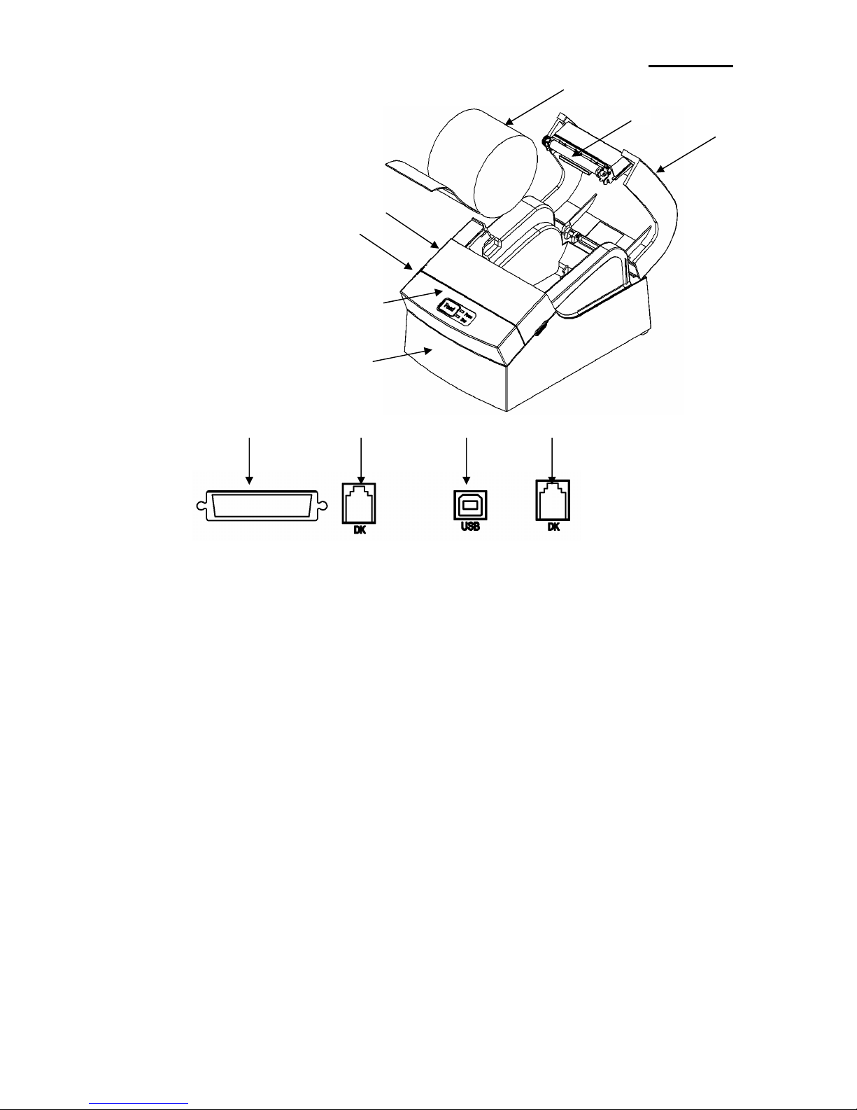
2-2 Interface Connection
USB, serial or parallel interface cable is required for connecting the printer to the computer.
- Make sure the power of the printer and computer is switched on, then connect the
cable interface to the printer.
- In the case of serial and parallel cable, assemble as the following picture shown.
- Connect the computer to the other end.
Make sure the power unit is removed from the plug of the device when the printer powers
on or off, otherwise damage may be caused to the printer and power unit.
1. Make sure the printer has been switched off and the power unit removed from the plug
of the device.
2. Check the label on the power unit to make sure the power plug is compatible with the
required voltage.
3. Connect the DC cable connector of the power unit to the power connector of the printer
as the following instruction.
25 Pin Female Type
Table of contents
Other FEC Printer manuals


