FeelElec FY6200 Series User manual

FeelElec
User’s Manual
FY6200 Series Fully Numerical Control
Dual Channel Function/Arbitrary
Waveform Generator
Rev2.0 April, 2019


FeelElec
FY6800 系列用户手册 I
Guaranty and Declaration
Copyright
© FeelElec Technology Co. Ltd. All Rights Reserved.
Trademark information
FeelElec is a registered trademark of Zhengzhou FeelElec Technology
Co., LTD.
Declaration
The company reserves the right to change specifications and
prices.
The information provided in this manual supersedes all previous
publications.
FeelElec shall not be liable for any errors that may be contained
in this manual, or for any incidental or consequential loss resulting from
the information and deductive functions provided in this manual, or
from the use of this manual.
No part of this manual may be reproduced or adapted without the
prior written permission of FeelElec.
Contact Us
If you have any problem or requirement when using our products or this
manual, please contact FeelElec.
Website:www.feelelec.com

Contents
Guarantee and Declaration.............................................错误!未定义书签。
Product Introduction ...............................................................................3
General Description .................................................................................6
General Inspection ....................................................................................6
Front Panel Overview ................................................................................7
Back Panel Overview ...............................................................................10
Power On and Inspection.........................................................................11
User Interface.........................................................................................12
Dimensions.............................................................................................14
Front Panel Operations ..........................................................................15
Waveform Output....................................................................................15
Select Output Channel....................................................................................15
Select Waveform............................................................................................16
Selevct Frequency..........................................................................................17
Set Amplitude................................................................................................18
Set Offset......................................................................................................19
Set Duty Cycle(Square)...................................................................................20
Set Phase......................................................................................................21
Enable Channel Output................................................................................... 22
Example: Output sine waveform...................................................................... 23
Generate burst waveform ............................................... 错误!未定义书签。
Digital Modulation .......................................................... 错误!未定义书签。
Frequency meter/counter ........................................................................30
Enable frequency meter.................................................................................. 30
Set the Counter .............................................................................................31
Sweep ....................................................................................................32
Sweep Object ................................................................................................32
Sweep Start Position .............................................................. 错误!未定义书签。
Scan Termination Position & Sweep Time ......................................................... 34
Sweep Type...................................................................................................35
Enable Frequency Sweep Function................................................................... 36
System Setup and Auxiliary Functions.......................................................38
Storage and Loading ......................................................................................39
Configuration................................................................................................. 40
Uplink................................................................................... 错误!未定义书签。
Synchronizing ................................................................................................41
Fault Handling........................................................................................42
Technical Indicator ................................................................................43
Appendix .........................................................................错误!未定义书签。

FeelElec
FY6200 系列用户手册 3
Product Introduction
This manual is applicable to various models of FY6200 series Function /
Arbitrary Waveform Generator. The last three digits in the model of FY6200
instrument indicate the upper limit value of sine wave frequency (MHz) of the
instrument. For example: the “60M” of the Model Number “FY6200-60M” indicates
the Sine wave maximum output frequency is up to 60MHz.
FY6200 series dual channel function / arbitrary waveform generator is a high-
performance, cost-effective and multi-functional signal generator which integrates
the functions of function signal generator, arbitrary waveform generator, pulse
signal generator, noise generator, counter and frequency meter. The instrument
adopts large-scale FPGA integrated circuit and high-speed MCU microprocessor,
the internal circuit uses high-precision active crystal oscillator as the reference,
and the signal has high stability. Surface mount technology greatly improves the
anti-interference and service life of the instrument. The instrument has completely
independent two-way DDS signal and four-way TTL level output, which can
generate 31 preset waveform signals such as sine wave, square wave, triangle
wave, sawtooth wave, pulse wave, white noise and 64 groups of user-defined
waveforms. The instrument is easy to use, excellent technical index and perfect
combination of many functional characteristics in signal generation, waveform
scanning, parameter measurement and use, which can help users complete work
tasks faster. It is an ideal testing and measuring equipment for electronic engineers,
electronic laboratories, production lines, teaching and scientific research.
FY6200 series dual channel function / arbitrary waveform generator has
humanized keyboard layout and indication, providing users with intuitive operation
interface. The display interface adopts 3.2-inch TFT color LCD with high resolution
of 320 * 240, which can display all parameters of two channels at the same time
and prompt the current key function. The fast key greatly simplifies the complex
operation process and greatly enhances the operability of the instrument. Users
do not have to spend a lot of time to learn and familiar with the operation of the
instrument, you can use it proficiently.

The instrument has the following excellent technical indicators and
Functional Characteristics:
◆ DDS direct digital synthesis technology is used to produce accurate, stable
and low distortion output signals.
◆ It adopts the embedded panel design of ABS plastic shell, which is
convenient to integrate with user's equipment and easy to install.
◆ Use the 3.2-inch (320 * 240) color display screen is used to display the
waveform parameters of two channels at the same time.
◆ Maximum output frequency 60MHz (sine wave), 250msa / s sampling rate,
14bits vertical resolution.
◆ Long press the “OK” key during use to quickly save the current output
parameter information of the instrument, and the saved parameters can be
loaded automatically after the next power on.
◆ Fully independent dual channel output (equivalent to two independent
signal sources), which can work synchronously and the phase difference can be
precisely adjusted.
◆ Standard channel tracking function. When tracking is turned on, all
parameters of the two channels can be updated according to the user's
configuration at the same time.
◆ It can output up to 98 groups of functions / arbitrary waveforms, including
34 groups of preset waveforms and 64 groups of user-defined waveforms. Preset
waveforms include sine wave, square wave (duty cycle adjustable), triangle wave,
pulse wave (pulse width and frequency can be accurately set), rising sawtooth
wave, falling sawtooth wave, step wave, trapezoid pulse wave, cinke pulse, narrow
pulse wave, noise wave, exponential rise, exponential fall, ECG, Lorentz pulse wave,
multi audio wave, CMOS (0-10V) and DC voltage, etc.
◆ There are 64 groups of arbitrary wave storage bits, each group of storage
depth is 8192 * 14bits.
◆ High frequency accuracy: Frequency accuracy can reach 10-6 orders of
magnitude;
◆ The frequency resolution is relatively high: the full-range frequency
resolution is 1uHz(0.000001Hz);
◆ Amplitude resolution is higher: Amplitude resolution can be as low as 1mV

FeelElec
FY6200 系列用户手册 5
(0.001V).
◆ It has a DC bias function of - 10V ~ + 10V (< 20MHz), with a resolution of
1mV.
◆ With -10V~+10V DC bias function (<20MHz), resolution up to 1mV
◆ The pulse width and frequency of the pulse wave are continuously
adjustable, and the adjustment range is 20ns-1s. The pulse amplitude can be
continuously adjusted between 0-10V, and the adjustment accuracy is 0.001V.
◆ The phase adjustment range of the two channels is 0~359.99°, and the
adjustment accuracy is 0.01°
◆ No range limit: The full range of frequency is not divided into gear switches,
program-controlled settings.
◆ With digital signal output function, it can realize any CMOS level with 0~10V
amplitude.
◆ Scanning function: It can scan the four properties of the signal: frequency,
amplitude, offset, and duty cycle. It has two scanning modes: linear scan and
logarithmic scan. The scan time can reach 999.99S. The start and end of the scan
can be set arbitrarily.
◆ Burst Output Function: There has Manual Trigger, internal CH2 Trigger, and
External Trigger for your options. It can output 1~1048575 pulse trains.
◆ Various modulation types: AM, FM, PM, ASK, FSK and PSK modulations.
◆ Storage feature: it can be store 20 groups of instrument state parameters
set by users, and call up and reappear at any time.;
◆ 100M Frequency meter function: It can measure frequency, period, pulse
width and duty cycle. Max. frequency workable is 100MHz and Min. frequency
workable is 0.01 Hz.
◆ Counter Function: It has 2 coupling measure modes including DC coupling
and AC coupling. This design can solve inaccuracy problem of AC coupling.
◆ All parameters can be calibrated by internal procedures;
◆ Equipped with powerful arbitrary waveform editing function, it can edit
arbitrary waveform on PC and download to instrument output waveform.
◆ Powerful communication features that can be controlled using a PC. Open
communication protocol makes secondary development very simple
◆ High reliability: Large-scale integrated circuit, surface mount technology,
high reliability, long service life
◆ Output short-circuit protection: All signal outputs can work under load short-

circuit conditions 60S or more.
◆ Optional FYV2000 series or fpa2000 series power amplifier of our company
can stably output the undistorted power signal of more than 20W in DC-10mhz
bandwidth. The maximum output power of FPA2000-50w can reach 60W, and the
maximum output power of FPA101a can reach 100W.
General Description
General Inspection
Please follow the items below when you receive a new FY6200 series
Function/Arbitrary Waveform Generator.
1.Inspect the shipping container for damage
Keep the damaged shipping container or cushioning material until the
contents of the shipment have been checked for completeness and the
instrument has passed both electrical and mechanical tests. The consigner or
carrier shall be liable for the damage to instrument resulting from shipment.
2.Inspect the instrument
If there is mechanical damage or missing, or the instrument fails electrical and
mechanical tests, please contact your FeelElec dealer.
3.Check the accessories
Please check the accessories according to the Appendix C ( packing lists). If
the accessories are incomplete or damaged, please contact your FeelElec sales
representative.

FeelElec
FY6200 系列用户手册 7
Front Panel Overview
The front panel is divided into easy to operate functional areas. This section
briefly introduces the front panel control components and screen interface.
1-1 Front Panel
Item
Description
Explain
1
LCD
The 3.2 inch TFT (320 x 240) color LCD displays the menu and
parameter settings, system status and prompt message of the
current function. Please refer to the “User Interface” section for
details.
2
Manu Buttons
Corresponding to the menu displayed on the left, press this soft key
to activate the corresponding menu.
3
Function
shortcut,
Function for
switching signal
generator
Waveform selection button:
—You can switch between sine, square wave,
triangle wave, and any type of arbitrary wave
—Change the selected channel signal type
Trigger and modulation function buttons
—Can set a specific number of pulse train output
function(BURS)
—Modulation mode can be set :ASK、FSK、PSK、AM、
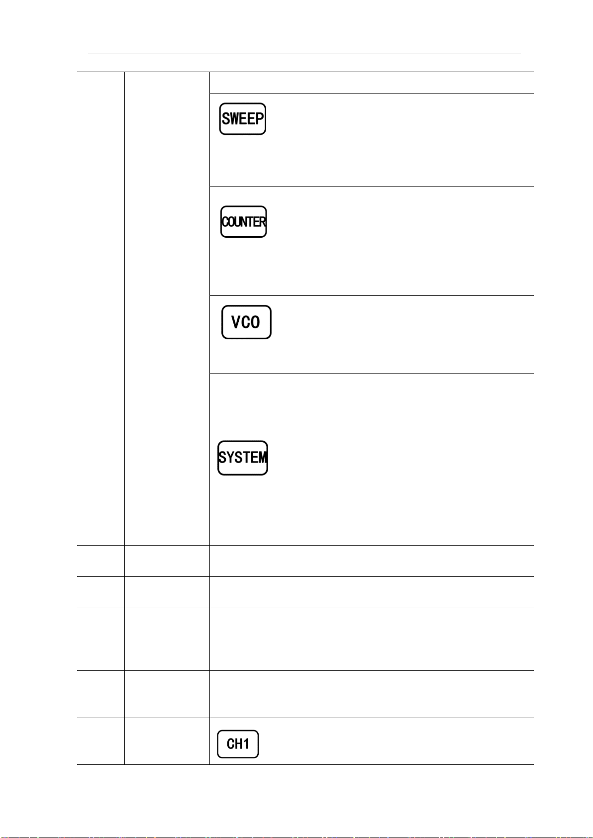
FM、PM
Sine, square, sawtooth and arbitrary waveforms can
be scanned.
—Supports scanning of four parameters of
frequency, amplitude, offset, and duty cycle.
—Supports two linear and logarithmic scanning
methods.
Can switch to frequency meter and counter function,
measure frequency, period, duty cycle, positive pulse
width of external input signal.
—Supports DC and AC signal input
—Supports 1 s, 10 s and 100 s gate time switching.
—Dual channel output can work with frequency
meter measurement.
VCO function can be set
—Support VCO voltage control signal generator's
frequency, amplitude, offset, duty cycle and other
parameter output functions (such as voltage-
controlled oscillator).
Used to set auxiliary function parameters and system
parameters.
—Supports storage of 20 sets of parameters such as
frequency, amplitude, offset, and phase
—Support Chinese and English switching
—Support prompt tone off/on
—Supports multi-machine cascading
—Supports master/slave switchover in cascaded
state
—Supports dual-channel power-on default output
state setting
4
Direction key
When the knob is used to set parameters, it is used to move the
cursor to select the bit to be edited.
5
Adjusting knob
When using the knob to set parameters, you can increase (clockwise)
or decrease (counterclockwise) the value at the current cursor.
6
Power button
The power indicator will remain on when it is turned on.
When the signal generator is turned off, the indicator light will enter
the breathing lamp state and CH1 and CH2 will stop outputting (the
output will remain at 0 volts).
7
CH1 channel
output
Connector
BNC connector, nominal output impedance 50Ω.
When channel CH1 is on (the CH1 button indicator lights up), the
connector outputs the waveform in the current configuration of CH1.
8
Channel
control,
Confirm button
It is used to control the output of the CH1 channel and
can be switched to the CH1 parameter setting interface
in any interface.

FeelElec
FY6200 系列用户手册 9
—Press this button, the CH1 light will turn on, and the
CH1 output will turn on. At this point, the [CH1]
connector outputs the signal in the current
configuration.
—Press this button again, the indicator light goes off,
and at this point, the CH1 output is turned off
Confirm button
—When editing frequency parameters, press this key
to change the frequency unit.
—When scanning the interface, press this button to
start/stop scanning.
It is used to control the output of the CH1 channel and
can be switched to the CH1 parameter setting interface
in any interface.
—Press this button, the CH2 light will turn on, and the
CH2 output will turn on. At this point, the [CH2]
connector outputs the signal in the current
configuration.
—Press this button again, the indicator light goes off,
and at this point, the CH2 output is turned off.
9
CH2 channel
output
connector
BNC connector, nominal output impedance 50Ω.
When channel CH2 is on (the CH2 button indicator lights up), the
connector outputs the waveform in the current configuration of CH2.
10
AC coupling
measuring
terminal
BNC connector, input impedance 100Ω. For inputting signal of meter
or counter.

Back Panel Overview
1-2 Back Panel
1. Power input interface, input voltage DC5V 1.5A.
2. USB Device Interface
Used to communicate with the computer. (this is a USB to TTL serial port. You
need to install a serial driver). Through the upper computer software or user-
defined programming.
Warning
In order to avoid damaging the instrument, the voltage range of
the input signal of the ext.in terminal shall not exceed ±20Vac +
dc. The input signal voltage range of Trig / FSK / ASK / PSK in
terminal shall not exceed DC5V.
Note
In order to ensure the normal operation of the instrument, please
use 5V 1.5A DC power supply.

FeelElec
FY6200 系列用户手册 11
Power On and Inspection
Connect to Power
Please use the power supply provided by the accessory to connect
to the DC power connector on the back of the signal generator. The
signal generator supports DC power of DC5V specification, and the
power consumption of the whole machine is less than 3W.
Power On
Turn on the power switch after the power cord is connected. The generator
will execute self-inspection. The LCD will show welcome interface after the
inspection is over. If the generator cannot work normally, please check the Chapter
“Fault Handing” for solution.
Set the System Language
FY6200 series Function/Arbitrary Waveform Generator supports Chinese and
English system languages. You can press SYSTEM→CONF to switch the system
language.
User Interface
The user interface of fy6200 includes four display modes: dual channel
parameter display mode, single channel extended display mode, additional
function display mode and system configuration display mode.
Dual Channels Parameters
The upper half of LCD displays the channel selected currently and the
parameters can be set. Press CH1 or CH2 to change current channel selected.
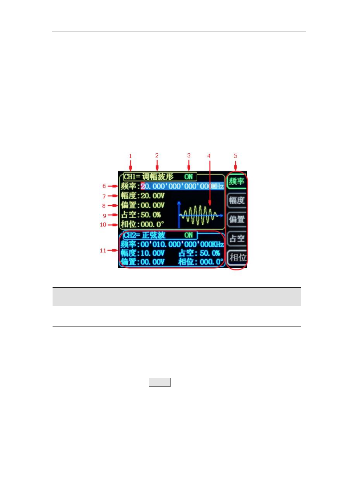
1-4 User Interface(CH1 channel is selected)
Item
Description
1
Current channel selected.
Display current channel selected for operation.
2
Current waveform type selected
Displays the name of the currently selected feature. For
example: "ch1 = amplitude modulation waveform" means that
the currently selected channel CH1 outputs amplitude
modulation waveform, and the waveform type can be changed
through the WAVE button on the front panel. In addition,
when the change waveform type function is activated, you can
use the parameter adjustment knob to perform fast switching
on the waveform type or click the knob to quickly locate the
waveform. In the waveform adjustment state, the preset
waveform and customization can be realized by pressing the
OK button. Fast switching between waveforms.

FeelElec
FY6200 系列用户手册 13
3
Currently selected channel output status bar
The current channel output on / off status is displayed, and
the output status can be changed by adjusting the front panel
channel control buttons CH1 and CH2.
4
Waveform
Display diagram of current waveform(Including Arbitrary).
Yellow indicates CH1 and blue indicates CH2.(The instrument can
also display any user-defined waveform.)
5
Manu Bar
Displays the action menu for the currently selected function.
6
Frequency
Displays the frequency of the currently selected channel
waveform. Press the corresponding FREQ button to highlight the
"frequency" display value, and change the parameter through
the direction key and adjustment knob.
7
Amplitude
Displays the amplitude of the currently selected channel
waveform. Press the corresponding FREQ button to highlight
the "amplitude" display value, and change the parameter
through the direction key and knob.
8
Offset
Displays the DC offset of the currently selected channel
waveform. Press the corresponding OFFS button to highlight the
"offset" display value, and change the parameter through the
direction key and knob.
9
Duty Cycle
Display Duty Cycle value of current channel. Press DUTY
button to highlight it and use adjusting Knob and Arrows to change
the value.
10
Phase
Displays the phase of the current waveform for each channel.
After pressing the corresponding PHAS button menu, change the
parameter with the arrow keys and knob.
11
Channel parameter status is not selected
Displays information such as the frequency, amplitude, offset,
phase, duty cycle, and output status of the current waveform of
the unselected channel. The parameters in this column cannot be
directly changed under the current interface. If you need to
change, please switch the channel to the selected channel.

Dimensions

FeelElec
FY6200 系列用户手册 15
Front Panel Operations
Waveform Output
FY6200 series can output waveforms (Sine, Square, Triangle/Ramp, Pulse and
Noise etc.) from one of the channels separately or from the two channels at the
same time. At start-up, the dual channels are configured to output a sine waveform
with 10kHz frequency and 5Vpp amplitude by default. Two channels use default
setting saved at Position 1 when power on. Users can configure the instrument to
output various waveforms.
Select Output Channel
CH1、CH2 keys are used to switch ch1 or CH2 to the currently selected
channel. When power on, ch1 is selected by default and displayed in yellow on the
top half of the screen. Press the CH2 key on the front panel to select CH2, which
is displayed in blue on the top half of the screen. After selecting the required output
channel, you can configure the waveform and parameters of the selected channel.
KEY POINT:
CH1 and CH2 can not be selected at the same time. Users can first select CH1 and
then select CH2 after configuring the waveform and parameters of CH1. If you need
to change the parameters of two channel at same time, please refer to Chapter
“Synchronizing”.

Select Waveform
FY6200 can output Function/Arbitrary Waveform including:
⚫Sine
⚫Square
⚫Triangle/Ramp
⚫Rise Sawtooth
⚫Fall Sawtooth
⚫Lorenz Pulse
⚫Multitone
⚫Noise
⚫Electrocardiogram (ECG)
⚫Trapezoidal Pulse
⚫Sinc Pulse
⚫Narrow Pulse
⚫Gauss White Noise
⚫Step Triangle
⚫Positive Step
⚫Inverse Step
⚫Positive Exponent
⚫Inverse Exponent
⚫Positive Falling Exponent
⚫Inverse Falling Exponent
⚫Positive Logarithm
⚫Inverse Logarithm
⚫Positive Falling Logarithm
⚫Inverse Falling Logarithm
⚫Linear FM
⚫AM
⚫FM
⚫Positive Half Wave
⚫Negative Half Wave
⚫Positive Half Wave
Rectification
⚫Negative Half Wave
Rectification
⚫User-defined waveform
Press WAVE to change waveform selected. Or rotate ADJ Knob under waveform
switching status to change waveform. The waveform diagram displays on the
screen. Pressing the knob can change to arbitrary waveform directly when
choosing waveform. At start-up Sine is selected by default. (Users can also
configure start-up waveform. Please check Chapter “Save and Load”.)
Waveform
Sine
Square
Triangle
Sawtooth
Arbitrary
Function Name
SINE
SQUR
TRGL
RAMP
ARB
Parameter
Frequency
√
√
√
√
√
Amplitude
√
√
√
√
√
Offset
√
√
√
√
√
Phase
√
√
√
√
√
Duty Cycle
√
Note: the user-defined waveform can be edited and downloaded through the
fy6200 upper computer control software provided by feelelec. Relevant software
and drivers can be downloaded from our website: http://www.feelelec.com

FeelElec
FY6200 系列用户手册 17
Set Frequency
Frequency is one of the most important parameters of the basic waveform.
The frequency can be set differently based on different signals and different
waveforms. Please refer to the description of “Frequency Characteristics” in
“Performance Specifications”. The factory default setting is 10KHz.
Press the FREQ soft key to highlight the frequency parameter. At this time,
use the direction key and knob to set the parameter value: use the direction key
to move the cursor to select the position to be edited, and then rotate the knob to
modify the value.
The frequency unit can be switched according to the user's requirements.
Press the OK key to change the frequency unit. The optional frequency units are:
MHz, kHz, Hz, MHz and μ Hz.

Set Amplitude
The settable range of amplitude is limited by the "frequency" setting. Please
refer to the description of "output characteristic" in "performance index". The
default is 5vpp.
Press the FREQ soft key to highlight the amplitude parameter. At this time,
use the direction key and the adjustment knob to set the value of the amplitude:
use the direction key to move the cursor to select the position to be edited, and
then rotate the knob to modify the value.
Key Points:
1.What is the difference between the amplitude in Vpp and the value in Vrms?
Answer:
Vpp is the unit of signal peak value, Vrms is the unit of signal effective value. Vpp is
used by default.
Explain:
For different waveforms, the relationship between Vpp and Vrms is different. Take the
sine wave as an example.
The relationship is shown in the figure below.
According to the above figure, it can be deduced that the conversion relationship
between Vpp and Vrms meets the following relationship:
Vpp = 2
2
Vrms
For example, for a sine wave with a current amplitude of 5Vpp, the converted value is
1.768Vrms.
This manual suits for next models
4
Table of contents
Other FeelElec Inverter manuals


Popular Inverter manuals by other brands

Goodwe
Goodwe Smart DT Series user manual

Hitachi
Hitachi BRD-EZ3-110K Specifications

Rotex
Rotex E-Solar Unit ESU 509 Installation and maintenance instructions

LG
LG MonoX ACe Installer's guide

EELP
EELP PSL Series Assembly, installation and operation instructions

sylber
sylber SOL R-7,5M Installation and maintenance manual


WEG
WEG CVW300G2 installation guide

AE Conversion
AE Conversion INV315-50EU Assembly and operating instructions

SycoTec
SycoTec easyDrive TV 4504 Short instructions for use

Fimer
Fimer PVS-12.5-TL product manual

Phocos
Phocos Any-Grid Series Settings guide

YASKAWA
YASKAWA PVI 23 TL Installation and operation manual