Feelgood mr. steam Club Therapy CT6E Instruction manual

mr
.steam
®
Feel Good Inc.
Clu Therapy Steam ath Generator Systems
Installation, Operation & Maintenance Manual Models: CT6E, CT9E, CT12E, CT15E
Installation, Operation & Maintenance Manual

Club Therapy®Steambath Generator Systems
INSTALLATION, OPERATION & MAINTENANCE MANUAL
Table of Contents
Read Me First! & Warning Placard .....................................1
Select Your Clu Therapy Model .......................................2
Specification Chart .............................................................2
Before Installing .................................................................3
Steam Room Guidelines.....................................................3
Locating the Steam Generator Unit ...................................4
Typical Installation ..............................................................5
Installation: Plum ing, Water Supply, Drain, Steam
Outlet, Safety Valve, Condensation Pan, AromaSteam ....6
Water Quality Information..................................................6
AromaSteam SteamHead Installation ................................7
Generator Dimensions .......................................................8
Electrical Specifications & Field Power Wiring ..................9
Wiring Diagrams...............................................................10
Initial Start-Up & Checkout, Maintenance, Generator
Operations and Trou leshooting..................................11
System Status Codes, Liquid Level Control Board ..........12
AutoFlush®System ...........................................................13
Condensation Pan, Express Steam®.................................14
Replacement Parts List.....................................................14
Replacement Parts Diagram.............................................15
Controls
Before Installing, Control Rough-In..................................16
CT SteamStop ..................................................................17
Care Tips for Controls and Steamhead............................17
General
Warranty ...........................................................................18
PUR
100426
REV
1.20
mr.steam®Sussman-Automatic Corp.®[email protected] www.mrsteam.com
43-20 34th Street, Long Island City, NY 11101 TEL: 1 800 76 STEAM
9410 S. La Cienega Blvd. Inglewood CA 90301 TEL: 1 800 72 STEAM
USA
Designed, Engineered
and Assembled in the
READ ME FIRST!
IMPORTANT NOTE:
As you follow these
instructions, you will notice warning and caution
sym ols. This locked information is important
for the safe and efficient installation and opera-
tion of this generator. These are types of poten-
tial hazards that may occur during this installa-
tion and operation:
states a hazard may cause seri-
ous injury or death if precautions are not fol-
lowed.
signals a situation where minor
injury or product damage may occur if you do
not follow instructions.
is used to address practices not
related to physical injury.
IMPORTANT NOTE:
This highlights infor-
mation that is especially relevant to a pro lem-
free installation.
All information in these instructions is ased on
the latest product information availa le at the
time of pu lication. Sussman-Automatic
Corporation reserves the right to make changes
at any time without notice. More current instruc-
tions may e availa le at
www.mrsteam.com.
When installing and using this electrical equipment, asic safety precautions
should always e followed, including the following:
IMPORTANT SAFETY INSTRUCTIONS
1. READ AND FOLLOW ALL INSTRUCTIONS
2. Do not permit children under the age of 16
to use this steam ath.
3.
To reduce the risk of injury:
A. The wet surfaces of steam enclosures may e slippery. Use care when
entering or leaving.
B. The steam head is hot. Do not touch the steam head and avoid the
steam near the steam head.
C. Prolonged use of the steam system can raise excessively the internal
human ody temperature and impair the ody’s a ility to regulate its
internal temperature (hyperthermia). Limit your use of steam to 10-15
minutes until you are certain of your ody’s reaction.
D. Excessive temperatures have a high potential for causing fetal damage
during the early months of pregnancy. Pregnancy or possi ly pregnant
women should consult a physician regarding correct exposure.
E. O ese persons and persons with a history of heart disease, low or high
lood pressure, circulatory system pro lems, or dia etes should consult
a physician efore using a steam ath.
F. Persons using medication should consult a physician efore using a
steam ath since some medication may induce drowsiness while other
medications may affect heart rate, lood pressure and circulation.
A warning placard has een provided in the Information
envelope. This placard is an essential part of providing
a safe environment for steam room users. This placard
must e mounted to the wall of the shower or steam
enclosure, at a point visi le to all users. Failure to
mount this placard may result in serious injury or death.
SAVE THESE INSTRUCTIONS
1
mr
.steam®
C L U B T H E R A P Y Installation, Operating & Maintenance Manual
_________________________________________________________________________________________
STEAM ROOM BENEFITS
Steam bathing is a communal activity. Enjoy steam together with friends. Relax, knowing
that steam may be a natural detox. Here are some possible benefits of steam bathing:
- Cleanses, nourishes, and hydrates skin
- Boosts metabolism
- Provides relief for respiratory ailments such as colds, flu, allergies, and asthma
- Reduces stress and promotes restful sleep
Follow your steambath with a refreshing shower.
If you would like your own personal steam bath at home contact us at mrsteam.com
REDUCE THE RISK OF OVERHEATING AND SCALDING
1. Exit immediately if uncomfortable, dizzy or sleepy. Staying too long in a
heated area is capable of causing overheating.
2. Children under the age of 16 should not use the steam bath.
3. Check with a doctor before use if pregnant, diabetic, in poor health or
under medical care.
4. Breathing heated air in conjunction with consumption of alcohol, drugs or
medication is capable of causing unconsciousness.
5. Do not contact steam head or steam at the steam head.
REDUCE THE RISK OF SLIPPING AND FALL INJURY
Use care when entering or exiting the steam room, floor may be slippery.
Note:
For additional safety considerations see owner's manual.
MrSteam 43-20 34th Street, Long island City NY 11101 1-800-76-STEAM www.mrsteam.com
HYPERTHERMIA occurs when the internal temperature
of the ody reaches a level several degrees a ove the
normal ody temperature of 98.6° F. The symptoms of
hyperthermia include an increase in the internal tem-
perature of the ody, dizziness, lethargy, drowsiness,
and fainting. The effects of hyperthermia include:
a) Failure to perceive heat;
) Failure to recognize the need to exit the steam ath;
c) Unawareness of impending risk;
d) Fetal damage in pregnant women;
e) Physical ina ility to exit the steam ath
and
f) Unconsciousness.
The use of alcohol, drugs, or medica-
tion can greatly increase the risk of hyperthermia.
not actual size

mr
.steam®
C L U B T H E R A P Y Installation, Operating & Maintenance Manual
_________________________________________________________________________________________
2
In considering a purchase of this steam-
ath system, please note that if users are pregnant,
have a coronary condition, are in poor health, are eing
treated for any other medical condition, or are using
medication or drugs, MrSteam recommends that you
o tain the approval of their physician efore use.
For information a out this product and safety issues,
please call us at 1-800-76-STEAM or log onto
www.mrsteam.com
IMPORTANT NOTES:
•
The guidelines for selecting the steam ath generator is
a recommendation only. Because of varia les in con-
struction, these sizing instructions and specifications
should e considered as guidelines only. MrSteam will
review the model selected provided we receive com-
plete information, including working drawings, specifi-
cations, and pertinent electrical and construction
details. Otherwise, the manufacturer disclaims respon-
si ility for the sizing of a model selected.
• For steam rooms constructed of acrylic or synthetic
materials, select next lower-rated CT model.
• The total adjusted room volume allows for up to 60
feet of insulated steam piping from the CT generator
to the steam room. If the 60 feet piping is exceeded
consult with factory. When locating the steam gener-
ator consideration of the control and external tem-
perature pro e must e taken into account. The max-
imum length for a control ca le is 60 feet. The maxi-
mum length of the MSTS is 60 feet. MSTS connects
to the steam generator and is required to e installed
inside the steam room when the control is mounted
outside the steam room.
Steam Generators Specification Chart
Amps (for Total A j Wire Water Usage Shipping
Mo el No. KW 240v/1PH)† Room Vol. Size‡ gallons†† Dimensions* Wt. (lbs)**
CT6E 6 25 150 8 0.80 17"L x 18½"H x 77⁄8"D 40
CT9E 9 38 360 8 1.2 17"L x 18½"H x 77⁄8"D 40
CT12E 12 50 575 6 1.6 17"L x 18½"H x 77⁄8"D 40
CT15E 15 63 675 4 2.0 17"L x 18½"H x 77⁄8"D 40
IMPORTANT NOTES:
• A C1 suffix to Mo el No. for 240V/1Ph; A B1 suffix to Mo el No. for 208V/1Ph.
• All CT MS Mo els are cUL us Liste an CE; approve .
All CT Generators availa le in 240v/1PH, 208v/1PH and other voltages/phases.
† Amps are for 240/1PH rated units.
‡Wire size (AWG) ased on minimum 90˚C rated THHN copper conductors. Refer to the
National Electrical Code for other types of conductors.
*Dimensions are for generator only, with-
out AutoFlush®or plum ing features.
**Shipping weight and pricing are for
generator only, without control or
steamhead.
†† Water usage ased on 20 minutes of
operation.
Materials of construction, room size and special design features such as
large glass areas, all affect the steam generator model selection.
1.
Measure length, width & height in feet of the steam/shower or tu /shower
Multiply the Length ____ x Width____ x Height _____ =
2. Construction Materials:
For natural stones: natural mar le, Add 110%
stone, shale, glass lock or concrete
For ceramic or porcelain tile on Add 40%
cement oard or mortar ed
3. Ceiling Height: For each foot a ove 8 feet
(max. of 10 feet) Add 15%
4. Add all figures a ove to o tain
the Total Room Volume required
ROOM
VOLUME
TOTAL ADJUSTED
ROOM VOLUME
Select Your Club Therapy Mo el
Compare your TOTAL ADJUSTED ROOM VOLUME to the Specification Chart
elow and select the appropriate model.
Visit www.mrsteam.com to size your generator automatically.

mr
.steam®
C L U B T H E R A P Y Installation, Operating & Maintenance Manual
_________________________________________________________________________________________
3
If acrylic, fi erglass or other non-heat resistant materials are
used as part of the steam room enclosure. Consult with the material manu-
facture and see pg. 7, “Installing the AromaSteam Steamhead" for addition-
al details.
IMPORTANT NOTES:
This document contains important safety, operation and maintenance infor-
mation. Leave this document with the clu /spa management.
Do not discard this document.
The following general information should e used in conjunction with con-
sultations with an architect, designer and contractor in determining factors
necessary in providing a suita le and safe steam room.
MrSteam CT steam generators are intended to e operated with MrSteam’s
iTempo/Plus™, iSteam®and CT SteamStop®only, and are to e installed
strictly in accordance with the specific instructions contained in this manual
and as supplied in the manuals provided with the controls or accessories.
Never use damaged equipment, doing so may
result in an inoperative or hazardous installation.
Discontinue use of the steam generator and control if the steam
generator or control are damaged or otherwise not functioning
properly. Doing so may result in an inoperative or hazardous
installation
ELECTRICAL SHOCK HAZARD. MrSteam steam generators are
connected to 208V or 240V line voltage and contain live electri-
cal components. All installation and service to e performed y
qualified and licensed electricians and plum ers only. nstallation
or service y unqualified persons or failure to use MrSteam parts
may result in property damage or in a hazardous condition.
Do Not alter or modify any MrSteam product.
Doing so may result in an inopera le or hazardous
installation and will void the warranty
8. Steam room tile construction information is availa le from the Tile
Council of America, Inc. y purchasing
the TCA Hand ook for Ceramic Tile Installation.at (864) 646-8453
or www.tileusa.com.
9. Windows that are part of the steam room should e dou le
paned and tempered safety glass.
10. Limit steam room ceiling height to 8 feet. Exceeding 8 feet may
require a higher-rated steam generator.
The warning
placard is located in the docu-
mentation envelope. This plac-
ard is an essential part of provid-
ing a safe environment for steam
room users. This placard must e
mounted to the wall of the
shower or steam enclosure, at a
point visi le to all users. Failure
to mount this placard may result
in serious injury or death. For a
replacement placard contact
MrSteam customer service at 1-
800-76-STEAM or
Before Installing
Carefully inspect the CT steam generator and packaging for
shipping damage. In the event of shipping damage, please
contact the carrier for claim information. Our customer service
department can assist you with any missing or damaged parts.
Read these instructions efore installation or service. Although
this CT steam generator has een fully qualified
for shipment y MrSteam, the following must e reviewed for
proper, safe and enjoya le steam athing:
1. Verify that the model and accessories specifications are cor-
rect for the incoming line voltage.
2. Insure steam ath generator has een correctly sized for the
steam ath room. Pay particular attention to room volume
Steam Room Gui elines
IMPORTANT NOTE:
Owners/Operators should o tain a
copy and familiarize themselves with the latest edition of the
American College Sports Medicine Health/Fitness Facility
Standards and Guidelines, or a similar resource and reference
pu lication, and refer to those guidelines for the proper and
safe operation of a spa facility including steam rooms.
1. Steam room must e completely enclosed, with full
walls, door, floor and ceiling.
2. It is recommended that a gasketed door is used for
steam containment.
3. If tile-type or other smooth surfaced flooring is used
provide suita le anti-skid strips or equivalent, to
prevent a slipping hazard.
4. Check the suita ility of any materials with the
manufacturer. Walls and ceilings must e constructed
of water-resistant, non-corrosive surface, such as tile,
mar le, molded acrylic, or other non-porous material.
5. The ceiling should e sloped to prevent dripping of
condensate.
6. Provide a floor drain.
7. No heating, venting or air conditioning devices
should e installed inside the steam room.
and construction. If any questions, please refer to MrSteam sizing
and selection guide on page 2.
3. Mar le or glass walls or ceilings “enlarge” the room’s size requir-
ing a generator larger than one ased only on the room’s cu ic
foot (L x H x W) volume.
4. The physical size of the unit, clearance for plum ing servicing,
and its distance from the steam room must all e considered
efore final installation.
5. Consider any controls and accessories efore initiating installa-
tion. Read the Installation & Operation Manual of all controls
and accessories availa le at
www.mrsteam.com/products/technical-downloads.html
STEAM ROOM BENEFITS
Steam bathing is a communal activity. Enjoy steam together with friends. Relax, knowing
that steam may be a natural detox. Here are some possible benefits of steam bathing:
- Cleanses, nourishes, and hydrates skin
- Boosts metabolism
- Provides relief for respiratory ailments such as colds, flu, allergies, and asthma
- Reduces stress and promotes restful sleep
Follow your steambath with a refreshing shower.
If you would like your own personal steam bath at home contact us at mrsteam.com
REDUCE THE RISK OF OVERHEATING AND SCALDING
1. Exit immediately if uncomfortable, dizzy or sleepy. Staying too long in a
heated area is capable of causing overheating.
2. Children under the age of 16 should not use the steam bath.
3. Check with a doctor before use if pregnant, diabetic, in poor health or
under medical care.
4. Breathing heated air in conjunction with consumption of alcohol, drugs or
medication is capable of causing unconsciousness.
5. Do not contact steam head or steam at the steam head.
REDUCE THE RISK OF SLIPPING AND FALL INJURY
Use care when entering or exiting the steam room, floor may be slippery.
Note:
For additional safety considerations see owner's manual.
MrSteam 43-20 34th Street, Long island City NY 11101 1-800-76-STEAM www.mrsteam.com
Not Actual Size

4
Locating the Steam Generator Unit
IMPORTANT NOTE:
The control ca les should e run in dedicated 1" conduit to
facilitate installation and service Select a location as near as practical to the steam room.
Typical locations include: closet, vanity ca inet, heated attic or asement.
The maximum length of the MSTS is 60 feet. MSTS connects to the steam
generator and is required to e installed inside the steam room when the control is mounted
outside the steam room.
(Items 1-7)
1. DO NOT install steam ath generator or plum ing lines in unheated attic or any
locations where water could freeze.
2. DO NOT install steam ath generator inside steam room.
3. DO NOT install steam ath generator outdoors or wherever environmental condi-
tions may affect the safety and/or performance of the generator.
4. DO NOT install steam ath generator near flamma le or corrosive materials or
chemicals such as gasoline, paint thinners, or the like. Installation in areas having
high concentrations of chlorine (such as pool equipment room) must e avoided.
5. Install steam ath generator on a solid and level surface. Provide supports under
steam generator when wall mounting. Keyhole slots are provided for wall mounting.
Insure the steam generator is properly secured and level when mounting with
keyhole slots.
6. Install steam ath generator in an upright position only.
7. Burn Hazard.
Steam piping, safety valve, drain valve, plum ing and steamheads
ecome hot during operation and remain hot after shutdown for a period of
time. Provide appropriate protection, including insulating plum ing lines.
Avoid plum ing runs and steamhead locations that can come in contact
with athers.
IMPORTANT NOTE:
(Items 8-11)
8. Install anti-water hammer device as necessary.
9.
Provide a minimum of 12 inches at oth ends and
top of the steam generator or as required for servicing. See page 8.
10. Provide unions as required to facilitate installation and disconnection of piping.
11. The controls should e placed in a location only accessi le y the facility’s staff.
The CT SteamStop®and remote sensor are required to e installed inside the
steamroom.
MrSteam Generators and controls are CE and UL listed.
The CT series of steam generators are for commercial use only.
mr
.steam®
C L U B T H E R A P Y Installation, Operating & Maintenance Manual
_________________________________________________________________________________________
mr
.steam®
C L U B T H E R A P Y Installation, Op rating & Maint nanc Manual
_________________________________________________________________________________________
5
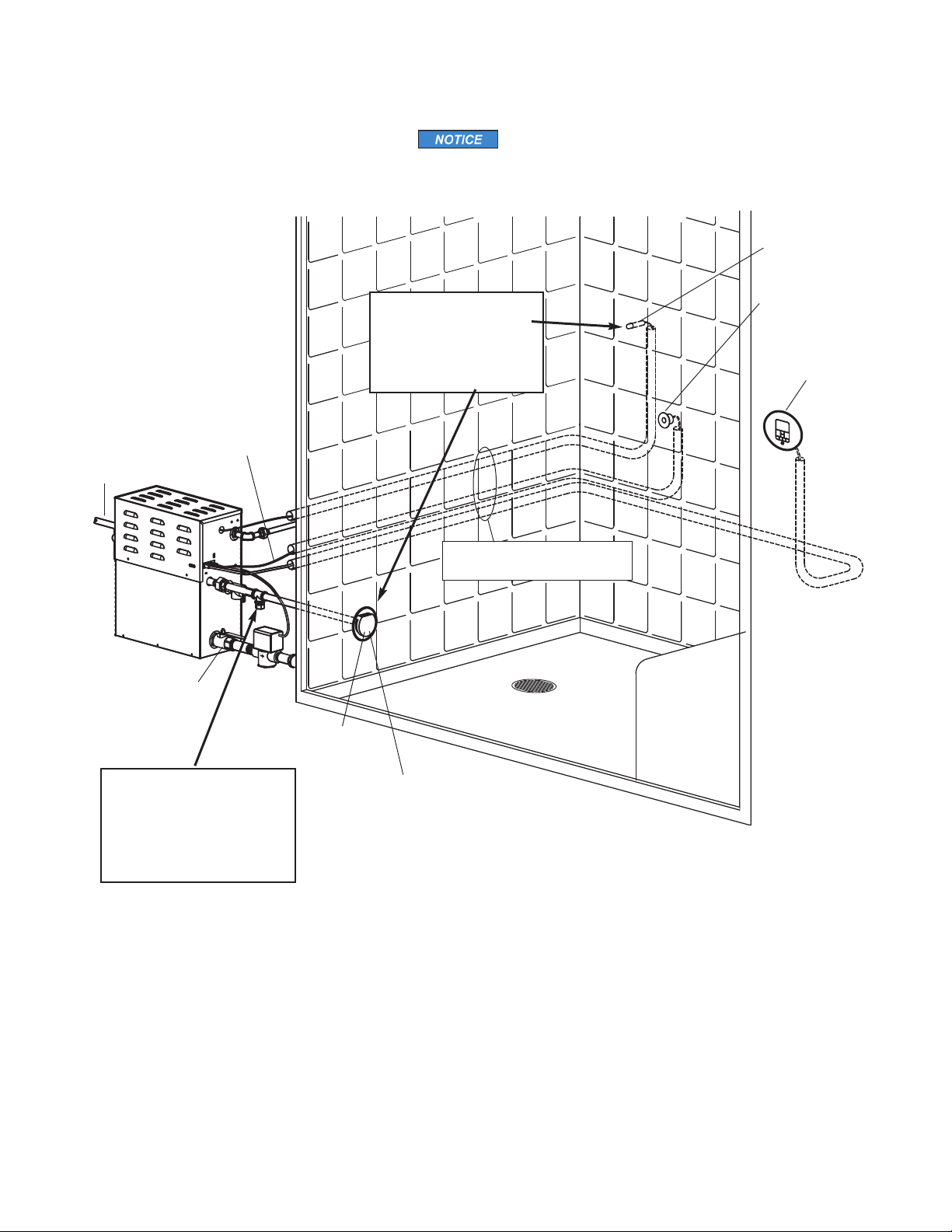
Provid unions as r quir d
to facilitat installation and
disconn ct of piping
St am
G n rator
Fi ld install d
pow r supply
Fi ld install d
st am piping
Drain Valv should
b clos d wh n
AutoFlush is not
install d
Control cabl s run in 1” conduit
(locat d b hind th wall)
St am H ad (shown with optional
acrylic shi ld) S pag 7 for
St am H ad Installation information
R mot S nsor
s pag 16
CT St amStop®
Control. S pag
17 for installation
information.
iT mpo/Plus®
or iSt am
Control. S
pag 16
Fi ld install d
wat r supply lin
IMPORTANT: Locat th
r mot s nsor in a location
r pr s ntativ of th d sir d
st ambathing t mp ratur s.
Do not locat th control abov
or n ar th st am h ad or
dir ct st am missions.
Typical MrSteam®Installation
Wh n installing th optional
AromaSt am, install a downward
facing 90-d gr T in th st am
piping. S th AromaSt am
Installation Manual for
compl t information.
FOR ILLUSTRATIVE PURPOSES ONLY
Som compon nts may b omitt d or alt r d for clarity. Do not us for
wiring, r pair or oth r purpos s not r lat d to compon nt id ntification.
mr
.steam®
C L U B T H E R A P Y Installation, Op rating & Maint nanc Manual
_________________________________________________________________________________________
6
Installation
Plumbing
All plumbing shall b p rform d by a qualifi d lic ns d plumb r
and in accordanc with applicabl National and local cod s.
•Us unions on all pip conn ctions.
• Us only brass piping or rigid copp r tubing as
p rmitt d by cod s.
• Do not us black, galvaniz d, PVC, or PEX pip .
Water Supply (3⁄8"N P T )
1. Conn ct to cold wat r lin .
2. Provid a shut off valv in th wat r supply lin upstr am
of th st ambath g n rator.
3. Do not ov rh at inl t sol noid valv with sold r conn ctions.
Ov rh ating will damag parts.
4. Flush inl t wat r lin thoroughly b for making conn ction
to unit.
5. Strain r r comm nd d upstr am of f d wat r conn ction.
6. For b st p rformanc wat r pr ssur should b 15 to 20 psig.
R duc pr ssur as r quir d.
7. Provid anti-wat r hamm r d vic as r quir d.
8. Install an approv d backflow pr v nt r as r quir d by local
cod s.
Drain
(1" N P T )
The drain from the generator should not share an undersin
trap, unless the generator is mounted higher than the sin .
A drain valv is provid d to facilitat
s rvicing. Provid a drain lin conn ction from st ambath
g n rator drain valv according to National and local Cod s.
Ch ck local plumbing cod for r c ptor, trap
and v nt r quir m nts. Do not conn ct Drain lin and Saf ty
Valv lin tog th r. Unit drains by gravity.
Do NOT conn ct th drain valv to th st am piping.
Safety Valve (3⁄4"
N P T
)
Wh r p rmitt d by local cod s, provid an outl t plumbing
conn ction for saf ty valv .
To insur prop r and automatic saf ty valv
op ration: DO NOT conn ct a shut off valv or a plug at saf ty
valv outl t. DO NOT conn ct a shut off valv or any construc-
tion in st am supply piping.
Condensation Pan
MrSt am strongly r comm nds th us of a cond nsation pan in
th unlik ly v nt of a plumbing l ak. Ch ck local plumbing
cod s for r c ptor, trap and v nt r quir m nts. Cond nsation
pans drain by gravity. Th cond nsation pan is quipp d with an
int gral 3⁄4" fitting. S pag 14 for additional cond nsation pan
installation information.
AromaSteam
If th optional AromaSt am El ctronic Oil D liv ry Syst m
(
PN
:
MS AROMA
) is to b install d, a 90 d gr Tplumbing fitting
must b install d at a d signat d location on th st am outl t lin .
S th MrSt am Aroma-St am Op ration and Instruction Manual
for installation information b for th st am piping is install d at
www.mrst am.com t chnical downloads.
Steam Piping (1⁄2"N P T )
1. Do not install any valv in st am piping. Flow of st am must
bunobstruct d.
2. Us 1⁄2inch brass pip or copp r tubing from unit to st am
h ad as p rmitt d by cod s.
3. Insulat st am piping with fib rglass pip insulation or
similar insulation rat d 212° F or high r.
4. Pitch st am piping 1⁄4"p r foot towards st am h ad or st am
g n rator to avoid vall ys and trapping of cond nsat .
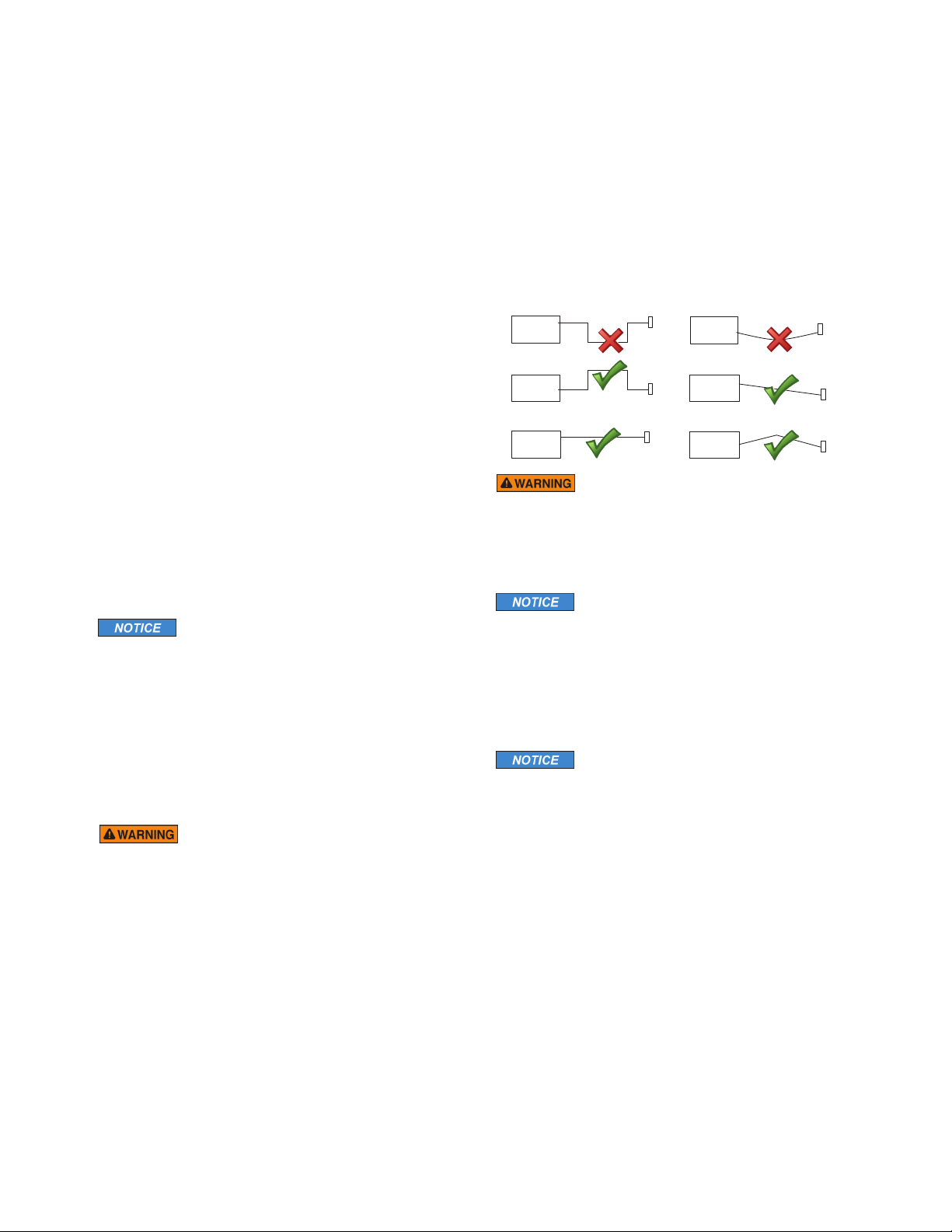
Failur to pitch th st am piping as r quir d for
cond nsat to drain, may caus cond nsat to block th flow of
st am. Blocking th st am flow may caus st am pr ssur to dis-
charg boiling wat r through th st amh ad, r sulting in a scald-
ing hazard. Blocking th flow of st am may caus st am to dis-
charg through th saf ty valv , r sulting in a scalding hazard.
A 1.5" hol in th st am room is r quir d to
mount th st amh ad.
Water Quality Information
For optimum r sults, th wat r supply should b t st d prior
to installation. If th min ral cont nt xc ds th following
r comm nd d limits, various xt rnal tr atm nt proc ss s ar
r comm nd d to corr ct th probl m.
An analysis of th on-sit wat r must b mad
by a r cogniz d and r liabl wat r tr atm nt company to
asc rtain th xisting condition and tr atm nt r quir d.
Poor wat r quality can aff ct ffici ncy or r sult in st am
g n rator damag . Wat r contains impuriti s in solution and
susp nsion. Th s impuriti s conc ntrat in th g n rator. Th
conc ntration of th s impuriti s incr as s as mor f dwat r
is introduc d into th g n rator and st am is produc d. If th
susp nd d solids ar allow d to conc ntrat b yond c rtain
limits, a d posit or “scal ” will form on th g n rator int rnal
surfac s. This d posit can int rf r with th prop r g n rator
op ration and caus g n rator failur . Th conc ntration of
th s impuriti s is g n rally controll d by th wat r quality
and by p riodic draining of th g n rator.
RECOMMENDED FEEDWATER QUALITY
Hardn ss, ppm 8 – 85 (~0.5 – 5 gpg)
P-Alkalinity, ppm 85 – 410 (~5 – 24 gpg)
T. Alkalinity, ppm 200 – 500 (~7 – 0 gpg)
pH (str ngth of alkalinity) 8.0 – 11.4
Th CT AutoFlush Syst m f atur automatically drains th
CT g n rator following ach us . A tim d lay allows th
wat r to cool down (about two hours) b for it drains by
gravity for a saf and g ntl op ration.
Steam
Generator
Steam
Generator
Steam
Generator
Steam
Generator
Steam
Generator
Steam
Piping
Steam
Head
Steam
Piping
Steam
Head
Steam
Piping
Steam
Head
Steam
Piping
Steam
Head
Steam
Piping Steam
Head
Steam
Generator
Steam
Piping
Steam
Head
mr
.steam®
C L U B T H E R A P Y Installation, Operating & Maintenance Manual
_________________________________________________________________________________________
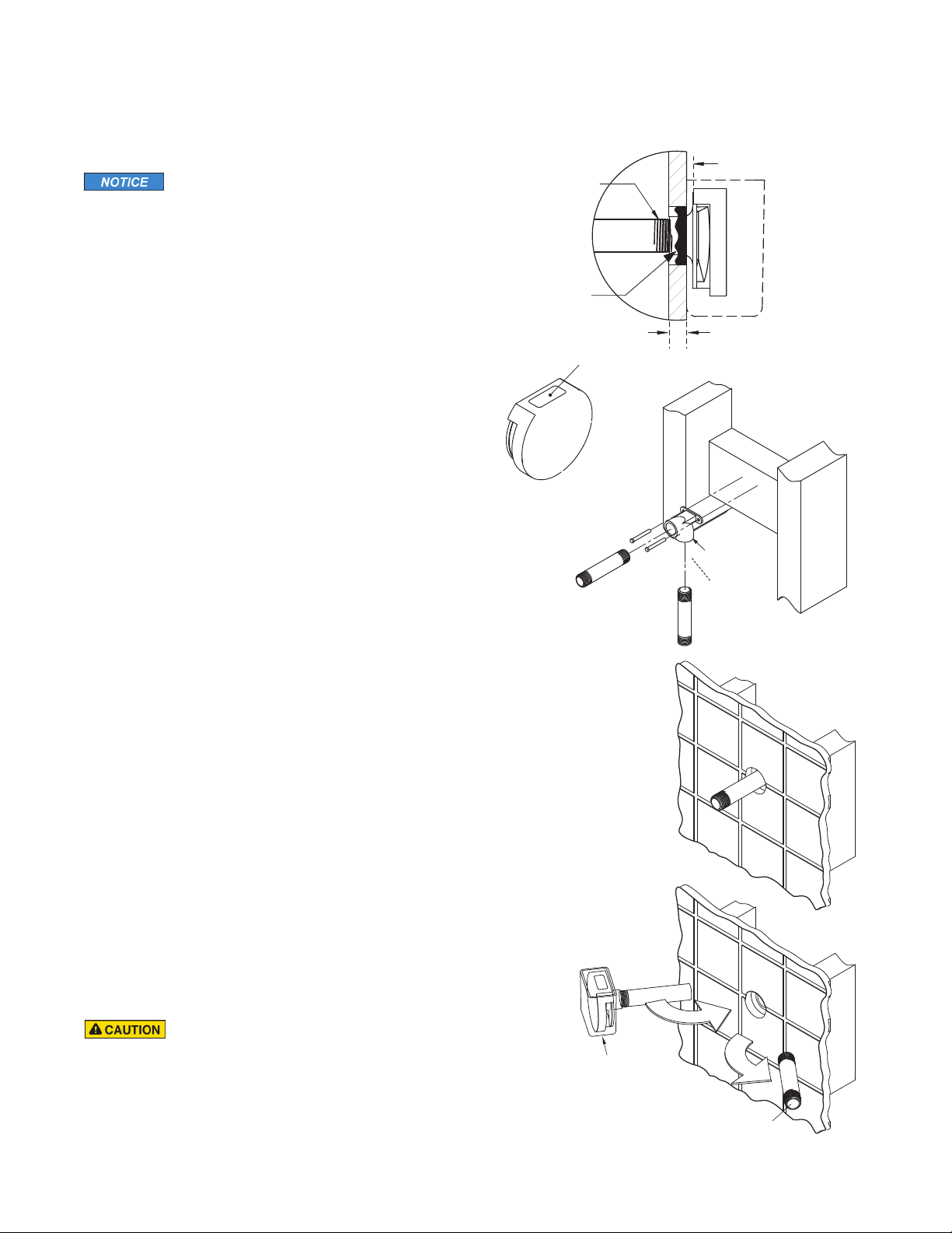
7
Steam Pipe
End of pipe to
be recessed 1/8"
1/8" minimum clearance
required for Acrylic Shield.
Apply with silicone
or equal sealant
as required for
moisture seal.
Use Teflon®or
equal sealant on
pipe threads
A 1
1⁄2
" clearance hole around the steam pipe is
needed to mount the steamhead.
STEP 1
Locate steam head 6-12 inches a ove floor, except for:
1. Tu /shower enclosures, install 6 inches a ove tu top edge.
2. Consult with supplier of acrylic, fi erglass and other non-heat
resistant enclosures for recommended steamhead location.
3. Use Acrylic Shield MS 103412. See instructions provided with
steam shield.
4. To reduce noise do not locate the steamhead within 12" from
a wall.
STEP 2
Install steamhead with the oil well facing up as shown.
Hand tightening is sufficient when teflon or equal pipe thread
sealing compound is used.
STEP 3
Secure a ronze drop ear fitting to a header and run a
1⁄2
"
copper steam pipe from the steam generator to the drop ear
fitting. Install a temporary nipple (6" or longer) in the drop ear
fitting to locate the steamhead after the wall is finished.
STEP 4
After the wall has een finished, mark on the nipple where the
surface of the wall is. Remove the nipple and measure the por-
tion that was in the wall (the end to your mark). Su tract 1⁄8" from
that dimension and select a rass nipple of that length to finish
the installation.
STEP 5
Wrap teflon tape around the threads of the new nipple and screw
the nipple into the steamhead. Do not use wrenches or tools which
would damage the steamhead's finish.
Wrap teflon tape around the threads of the nipple and screw the
nipple and steamhead assem ly you just made into the drop ear fit-
ting in the wall. The steamhead should e flush with the wall and
the well must e facing up.
__________________________________________________________
IMPORTANT NOTE:
•Do not disassem le steamhead. MrSteam’s steamhead is
shipped fully assem led and requires no additional assem ly.
• To preserve steam head finish, do not use wrenches or other
tools to tighten. DO NOT use a rasive cleansers or chemicals.
Use only water with mild soap and a non-a rasive sponge.
Because the steam head and direct steam emissions are very hot,
locate the steam head where incidental contact y ather with
the steam head or direct steam emission cannot occur.
Oil Well
STEP 3
STEP 4
STEP 5
Installing the AromaSteam Steamhea (1⁄2" NPT)
Steamhead
(shown with acrylic shield)
Locating ipple
Drop Ear
Fitting
All drawings are for illustrative purposes only

mr
.steam®
C L U B T H E R A P Y Installation, Operating & Maintenance Manual
_________________________________________________________________________________________
8
17"
(432)
2
3/8
"
(60)
23/8"
(60)
71/4"
(184)
121/2"
(310)
13/4"
(45)
183/4"
(466)
4"(102)
6"(152)
97/8"
(251)
13/8"
(35)
63/8"
(162)
77/8"(200)
12”(305)
for servicing
WATER INLET 3/8” NPT
STEAM OUTLET 1/2” NPT
SAFETY VALVE 3/4” NPT
MANUAL DRAIN VALVE 1” NPT
AUTOFLUSH VALVE 1” NPT
1. M= Optional AutoFlush
2. All units in inches (MM)
Water Inlet
Steam Outlet
Safety Valve
AutoFlush
Manual
Drain Valve
Generator Dimensions
IMPORTANT NOTES:
• Provide a minimum of 12 inches at oth ends and top
of the steam generator or as required for servicing.
Alternately, provide unions as required to facilitate
installation and disconnection of the steam generator.
• The minimum clearance from com usti le surfaces is
zero all around.
TO AVOID EQUIPMENT DAMAGE DO NOT CONNECT
POWER SUPPLY DIRECTLY TO ELEMENTS !!!
All drawings are for illustrative purposes only
Water Inlet
Control &
Accessory
Connections
Steam Outlet
Safety Valve
Manual
Drain Valve
Side View
Showing Element
Access Panel
mr
.steam®
C L U B T H E R A P Y Installation, Operating & Maintenance Manual
_________________________________________________________________________________________
Electrical
All electrical wiring to e installed y a qualified licensed elec-
trician in accordance with National Electrical Code and local
electrical code.
Power Wiring-
See “Field Power Wiring” Diagrams ( elow)
1. Check power voltage. Use 240V rated unit when supply is
greater than 208V. Use 208V rated unit for 208V power.
2. Use minimum 90˚ C/300V rated insulated copper conductors
only, sized in accordance with National Electrical Code and
local electrical code for the current in Ampere Chart. If
allowed y codes, NM ca le may require a larger wire size
than as listed on the chart.
3. Connect suita ly sized equipment grounding wire to ground
terminal provided.
4. Install a separate circuit reaker etween supply and unit.
Provide a power supply disconnect within sight of the steam
generator or one that is capa le of eing locked in the open
position.
5. For single phase units, use two-wire supply source and equip-
ment grounding wire. Neutral (white) wire is not required.
CHART
___________________________________________________________________________
Model Max Room KW Volts Wire Size Wire Size
o. Vol (Cu. Ft.*) 1 PH
†
Phase Amps (AWG) for 40˚C (AWG) for 45˚C
Ambient Ambient
___________________________________________________________________________
208 1 29 88
CT6E 150 6.0 3 17 10 10
240 1 25 88
314 12 12
___________________________________________________________________________
208 1 44 8 6
CT9E 360 9.0 3 25 88
240 1 38 88
3 22 10 10
___________________________________________________________________________
208 1 58 64
CT12E 575 12.0 3 34 88
240 1 50 66
3 29 88
___________________________________________________________________________
208 1 73 43
CT15E 675 15.0 3 42 86
240 1 63 44
3 36 88
____________________________________________________________
*See page 2 for room sizing.
†All specifications shown are for 208V and 240V. Consult factory for
other voltage specifications.
Provi e a power supply isconnect within sight of the steam
generator or one that is capable of being locke in the open position as permitte by co e.
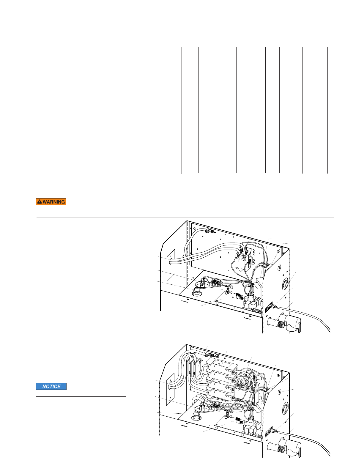
Transformer
Liquid Level
Control Board
Water Feed
Solenoid
Water Inlet
Thermostat
Liquid
Level Probe
Power Block
Power Supply
Knock-Out
Contactor
Steam Outlet
Fuses
AutoFlush Plug and
Play Connector
(see page 13)
Transformer
Liquid Level
Control Board
Water Feed
Solenoid
Water Inlet
AutoFlush Plug and
Play Connector
(see page 13)
Thermostat
Liquid
Level Probe
Power Supply
Knock-Out
Contactor
Steam Outlet
Fiel Power Wiring
1. TO AVOID EQUIPMENT DAMAGE
DO NOT CONNECT POWER SUPPLY
DIRECTLY TO ELEMENTS!!!
2. L1, L2, Ground to e field wired
Mo els CT6E – CT9E
(single phase wiring shown)
Mo els CT12E & 15E
(single phase wiring shown)
FOR ILLUSTRATIVE PURPOSES ONLY
Some components may e omitted
or altered for clarity. Do not use for
wiring, repair or other purposes not
related to component identification.
9

mr
.steam®
C L U B T H E R A P Y Installation, Operating & Maintenance Manual
_________________________________________________________________________________________
10
CONTACTOR
To Probe
HEATING ELEMENT
MSTS
TEMP. PROBE
AutoFlush
CT-SteamStop
iTempo/Plus or
iSteam Control
Transformer
POWER INPUT
L1 L2
GROUND
Express
Steam
WATER
FEED
SOLENOID
VALVE
THERMOSTAT
THERMOSTAT
HEATER
C
PURPLE
CONTROL BOARD
WHT/GRAY
WHT/BLUE
RED
WHT/RED
Remove Jumper
when CU-HTC
is installed
CONTROL BOARD
CONTACTOR
Heating Element To Probe
AutoFlush
CT-SteamStop
iTempo/Plus or
iSteam Control
TRANSFORMER
POWER INPUT
L1 L2
FUSES
GROUND
WATER
FEED
SOLENOID
VALVE
Express
Steam
THERMOSTAT
HEATER
Remove Jumper
when CU-HTC
is installed
AutoFlush
CT-SteamStop
iTempo/Plus or
iSteam Control
RED
MSTS
TEMP. PROBE
THERMOSTAT
Remove Jumper
when CU-HTC
is installed
Single Phase
Wiring Diagrams
MODEL CT6E & CT9E
MODEL CT12E & 15E
Three Phase
Wiring Diagrams
MODEL CT6E, CT9E
CT12E & CT15E
FACTORY
WIRING
FIELD
WIRING
L E G E N D
(All Diagrams)
mr
.steam®
C L U B T H E R A P Y Installation, Operating & Maintenance Manual
_________________________________________________________________________________________
Maintenance
MrSteam steam ath generators require little maintenance.
Other than draining, maintenance procedures are minimal. When
AutoFlush is not installed the manual drain valve should e opened
fully flushing out accumulated materials, salts and other particles
which are natural y-products of oiling water, after each use.
Flush a minimum of two-three hours after the control
has een turned off to insure that the water has cooled.
Draining immediately after a steam cycle may
expose PVC and other piping to high temperature water. Check
local codes. The unit will refill automatically after 10 minutes. In
areas of hard water, a MrSteam AutoFlush®system is recommended
for generator longevity.
Steam Generator Operation
MrSteam recommends eginning steam athing at a low tempera-
ture setting to gauge comfort and safety levels. Set the duration at
10 minutes max. to gauge comfort and safety levels. This will allow
the steam generator to heat up and egin producing.
11
Initial Start-Up an Checkout
1. Turn on control. Follow specific instructions provided
with controls.
2. Steam will egin to appear in approximately 5 min-
utes at the steam head. Steam will shut off when
desired temperature is reached and will automatically
resume when room temperature drops elow set
point.
3. Steam will shut off automatically when control counts
down to zero. To shut steam off manually, turn con-
trol OFF. To clear steam from enclosure area, turn
shower on efore opening door.
4. If unit does not start and control does not turn ON
(control display does not light up) then turn reaker
off for 20 seconds and try again.
5. Refer to specific instruction sheets for installation,
operation and maintenance of optional equipment
and Control.
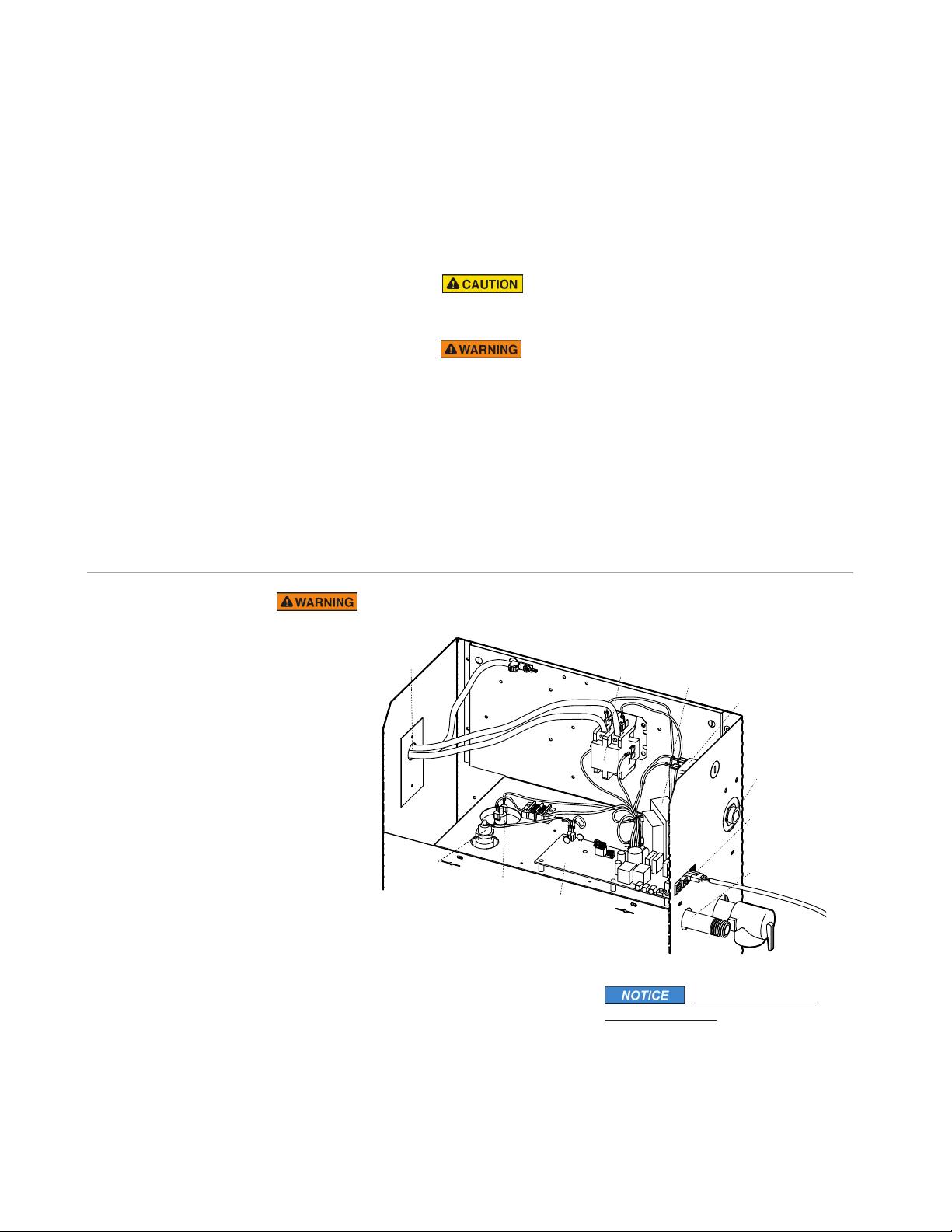
Transformer
Liquid Level
Control Board
Water Feed
Solenoid
Water Inlet
AutoFlush
Plug and Play
Connector
Thermostat
Liquid
Level Probe
Power Supply
Knock-Out Contactor
Steam Outlet
Troubleshooting
Step 1
Check your main incoming power
to the unit.
Step 2 Verify the transformer is receiving
208/240 VAC.
Step 3 Verify that you have 24VAC coming
out of the transformer, WHT & WHT/BLU
wires, into the oard.
Step 4 Verify that you have the green light
on the PC oard.
Step 5 Push the white test utton to run
the generator on a 10 minute test cycle.
Step 6 Verify that you have 24 VAC to the
water feed solenoid, GRY & WHT/GRY
wires (will fill when needed).
Step 7 Temporarily short out the WLS
(Purple wire) and GND (Green wire)
terminals and verify the contactor engages.
Step 8 When the red light is on, verify that
you have 24 VAC, RED & WHT/RED wires,
to the contactor.
Step 9 Check to see that you have your
main voltage on the load side of the
contactor when it is engaged.
Step 10 If all steps on the power path
were verified, turn off power to the unit
and pull the heating element via the left
hand access panel for inspection.
Do not isassemble internal components, internal components contain no serviceable parts.
FOR ILLUSTRATIVE
PURPOSES ONLY.
Some components may e omitted
or altered for clarity. Do not use for
wiring, repair or other purposes not
related to component identification.
All electrical trou leshooting to e performed y a qualified licensed electrician.
mr
.steam®
C L U B T H E R A P Y Installation, Operating & Maintenance Manual
_________________________________________________________________________________________
12
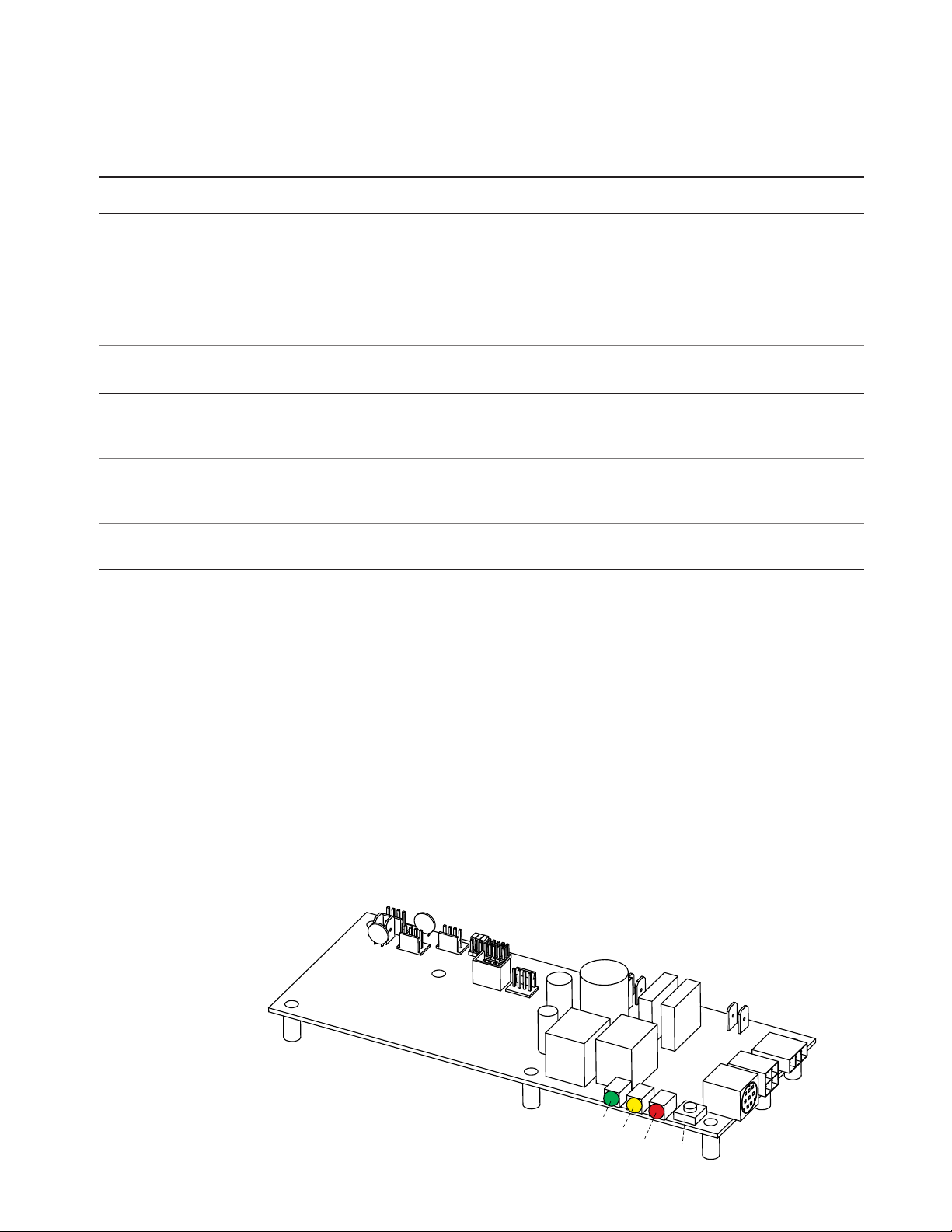
Force On
Test Button
Yellow (Water Level)
Green (Power)
Red (Heater)
System Status Co es
The iTempo/Plus control may display a status code if the steam generator is not functioning properly.
Co e Co e Meaning Probable Cause Suggeste Reme y
H20 Water level is not Water Supply is off Turn on Water Supply
satisfied within 5 min. Defective water feed solenoid Check/replace water solenoid valve
Water feed pro e not functioning Check/clean pro e.
Check pro e wiring.
Drain Valve Open Check/Close drain valve
AutoFlush not functioning Check/Replace AutoFlush
Prr1 Temperature Pro e Error Control/Remote sensor ca le cut Replace Control Ca le/Sensor
or Prr2 Internal pro lem with control/Remote Sensor Replace ControlSensor
Err1 Incorrect Field Supply Voltage Incorrect voltage supplied Supply steam generator with the correct
(green light on liquid level to Generator voltage noted on the data plate la el.
control oard will e off)
Err2 Button on control is pressed Control cover misalignment Remove and reinstall control cover
for more than 5 minutes De ris ehind control cover Remove control cover and clean cover,
control and keypad with a damp cloth
Err7 Liquid Level Control Board Memory error in LLCB Press ON/OFF to clear.
malfunction Replace control if code remains.
Liqui Level Control Boar -
EXPLANATION OF LED INDICATORS
_____________________________________________________________________________________________________________________________________________
GREEN LED is ON when there is 208/240 Volt incoming power connected,
24 Volt transformer secondary output and on- oard 5 Volt DC control power are present.
_____________________________________________________________________________________________________________________________________________
YELLOW Water level indicator–LED is OFF when no water is detected (for more that 5 seconds). ON when
water level is satisfactory. For units with AutoFlush, if more than five hours have elapsed since
last usage and this LED is ON it is indicative of an AutoFlush or water level pro e circuit malfunction.
_____________________________________________________________________________________________________________________________________________
RED Contactor relay indicator–LED is ON when relay is closed and sending 24 Volts to the
contactor coil. (This LED comes ON if the generator is ON.)
_____________________________________________________________________________________________________________________________________________
FORCE ON This utton is for trou le shooting only and will operate if a control is connected or not.
TEST BUTTON Pressing the utton again will shut the generator OFF.
The test utton will only allow the generator to operate for 10 minutes.
_____________________________________________________________________________________________________________________________________________
Liqui Level Control Boar
PN 104288
(shown without wiring)

mr
.steam®
C L U B T H E R A P Y Installation, Operating & Maintenance Manual
_________________________________________________________________________________________
13
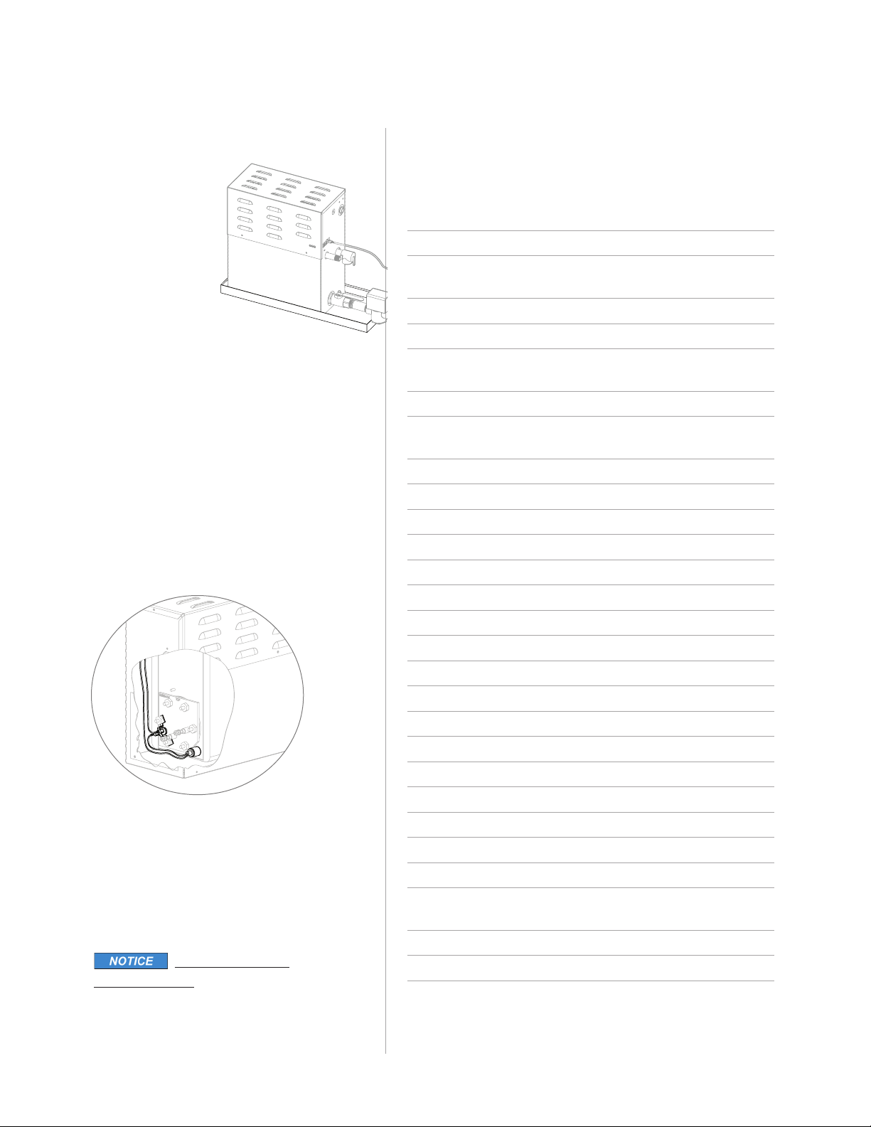
AutoFlush®
Box Contents
•AutoFlush Valve with Cord
• Installation instructions.
Operation
The AutoFlush System feature automatically
drains the CT system following each use.
A time delay allows the water to cool down
(a out two hours) efore it drains y gravity for a
safe and gentle operation. Unit drains by gravity.
Installation Instructions
1. Plum ing to e performed y a qualified
plum er and shall e in accordance with
applica le national and local codes. Unit drains
y gravity. A drain line that is lower than the
AutoFlush assem ly must e availa le. The
AutoFlush System valve outlet is 1" NPT. Check
plum ing code for receptor, trap and vent requirements.
2. Use copper or rass nipple 1" NPT x 31⁄2" or longer
(not supplied) to connect AutoFlush valve to the Drain Valve,
noting the direction of flow on the valve ody.
DO NOT REMOVE THE DRAIN VALVE
Removal may cause equipment and property damage.
If there is not enough room for the valve, an el ow and
a short nipple (not provided) can e added.
3. Open Drain Valve (handle must e aligned with rass nipple).
4. Connect the AutoFlush System cord connector to
the three pin connector as shown.
Do not drain into a steam enclosure or any
location where accidental contact with drain water may occur.
In the event of a power failure the AutoFlush System valve will
open and may discharge oiling water.
Sweat Fittings
When using sweat fittings use only tin ase solder with a melt-
ing point elow 600 degrees F. Do not overheat. Ends of water
supply tu ing must e thoroughly clean for a minimum distance
of 1" from ends. Do not remove valve cover.
To Check Operation
1. Turn on MrSteam and allow tank to fill with water.
2. Turn off MrSteam control. Water should stay in tank.
3. Turn off power at the panel ox. Water should
discharge from tank.
4. Turn on power at panel ox.
5. Repeat
Drain Valve
DO NOT TURN OR REMOVE
THE DRAIN VALVE
(shown in the correct open position)
Steam Generator
ipple Plumb to
Drain Line
AutoFlush Valve
AutoFlush Cord
AutoFlush Valve
3 Pin Connector
for AutoFlush
AutoFlush Cord Connector
Drain Valve
(shown in the correct open position)
DO OT REMOVE THIS DRAI VALVE
Steam Generator
ipple
copper or brass
nipple 1" PT x
31⁄2"or longer
(not supplied)
Plumb to
Drain Line
Arrow indicates correct
direction of flow
PROVIDE DRAIN PLUMBING ACCORDING
TO LOCAL CODES. PLUMB AS REQUIRED
FOR AUTOFLUSH SYSTEM.
mr
.steam®
C L U B T H E R A P Y Installation, Operating & Maintenance Manual
_________________________________________________________________________________________
14
Con ensation Pan
MrSteam provides a
condensation pan in
the unlikely event of
a plum ing leak.
Locate the conden-
sation pan on a solid
level surface and
place the steam
generator inside the
condensation pan.
Insure the steam
generator is level (see page 4 for locating
the steam generator).
All plum ing shall e performed y a qualified
licensed plum er and in accordance with appli-
ca le national and local codes. Check local
plum ing code for receptor, trap and vent
requirements.
Condensation pans drain y gravity. The conden-
sation pan is equipped with an integral 3⁄4" NPT
fitting.
Express Steam
®
(Factory installed)
All CT models have Express Steam standard.
Express Steam is equipped with a low power
heating element and thermostat to keep the
water in the tank warm enough to ring up
steam quicker. All Express Steam components
and wiring are installed at the factory. No
additional wiring or plum ing is required y
installers.
FOR ILLUSTRATIVE
PURPOSES ONLY
Some components may e omitted or altered
for clarity. Do not use for wiring, repair or other
purposes not related to component identification.
Replacement Parts List
____________________________________________________________
Part No. Description Pro uct
____________________________________________________________
99178CT Drain Valve All models
99297 Safety Valve 15PSI All models
100479-2 Water Feed Solenoid All models
Valve w/filter
100477-3 Transformer 24VAC All models
104288 Liquid Level Control Board All models
103990-60 Ca le for iTempo/Plus iTempo/Plus only
Control (60 ft.)
MSTS-60 Remote Temperature Pro e iTempo/Plus only
100476-2 Contactor 50A 2-pole CT6E & CT9E,
Single phase
99012 Contactor 50A 3-pole All 3-Phase models
103453 Contactor 50A 4-pole CT12E
100471-2 Pro e Assem ly All models
99096MS Heating Element Gasket All models
103412 Acrylic Shield All Models
99314 Power Fuse 60A 250V CT12E, Single phase
29061BMS Heating Element 6 KW 208V CT6E
29061CMS Heating Element 6 KW 240V CT6E
29091BMS Heating Element 9 KW 208V CT9E
29091CMS Heating Element 9 KW 240V CT9E
29121BMS Heating Element 12 KW 208V CT12E
29121CMS Heating Element 12 KW 240V CT12E
29151BMS Heating Element 15 KW 208V CT15E
29151CMS Heating Element 15 KW 240V CT15E
103978-60 Ca le for CT-SteamStop (60 ft.) All models
104016 Thermostat All models
104015 Express Steam Thermostat All models
104019 Heating element All models
for Express Steam
104117-30 Ca le for iSteam (30 ft.) iSteam Only
104117-60 Ca le for iSteam (60 ft.) iSteam Only

mr
.steam®
C L U B T H E R A P Y Installation, Operating & Maintenance Manual
_________________________________________________________________________________________
Mo els CT6E & CT9E
shown with cover removed
FOR ILLUSTRATIVE
PURPOSES ONLY.
Some components may e
omitted or altered for clarity.
Do not use for wiring, repair
or other purposes not related
to component identification.
Mo els CT12E & 15E
shown with cover removed
FOR ILLUSTRATIVE
PURPOSES ONLY.
Some components may e omitted
or altered for clarity. Do not use for
wiring, repair or other purposes not
related to component identification.
15
Transformer
Drain
Line
Liquid Level
Control Board
Fuses
Water Inlet
Water Feed
Solenoid
Safety
Valve
AutoFlush
Valve
Stainless
Steel Tank
Heating
Element
Access Cover
Thermostat
Liquid Level Probe AutoFlush Plug and
Play Connector
(see page 13)
Power Block
Power Supply
Knock-Out
Steam Outlet
Express
Steam
Contactor
Contactor
Transformer
(100477-3)
Drain
Line
Liquid Level
Control Board
(104288)
Water Feed
Solenoid (100479-2)
Water Inlet
Safety
Valve
AutoFlush
Valve (CT81500)
Stainless Steel Tank
Heating Element
Express Steam
(104019)
Access Cover
Thermostat
(104016)
Liquid Level
Probe
(100471-2)
AutoFlush Plug and
Play Connector
(see page 13)
Power Supply
Knock-Out
Steam Outlet

Do not route iSteam, iTempo/Plus, iTempo,
HomeWizard or iGenie control wiring inside conduit
together with power lines or close to hot water or steam
piping. Doing so may result in an inoperative or hazardous
installation.
Do Not alter or modify any MrSteam prod-
uct. Doing so may result in an inopera le or hazardous
installation and will void the warranty
IMPORTANT NOTES:
1. Turn power to the steam generator OFF efore con-
necting the control to the generator. Failure to turn the
power off will result in an inopera le control.
2. Do not operate iSteam, iTempo/Plus, iTempo,
HomeWizard or iGenie controls with other than a
MrSteam iSteam or iTempo compati le steam genera-
tor. MrSteam steam generators with serial num ers
lower than 900000, or any other rand of steam gener-
ator are not to e operated with iTempo controls.
Doing so may result in an inoperative or hazardous
installation. If iSteam is used with a generator having
serial num er less than 1174000, contact MrSteam
technical support for an upgraded PC oard.
3. This document contains important safety, operation and
maintenance information. Leave this document with
management. Do not discard this document.
4. Discontinue use of the steam generator or control if the
steam generator is damaged or otherwise not function-
ing properly. Operating a damaged steam generator
may result in an inoperative or hazardous installation
16
mr
.steam®
CLUB THERAPY Controls
_________________________________________________________________________________________
Control Rough In
Refer to Installation Instructions for the specific control
IMPORTANT NOTE: The control ca les should e run in dedicated 1" conduit to facilitate installation and service.
1. Determine the desired installation location of the
control. The iSteam®, iTempo™and iTempo/Plus™
controls are designed to e installed inside or out-
side the steam room as a matter of personal prefer-
ence. If the control is installed inside the steam
room the control must e located:
2.
4-5 feet a ove the floor near the ather seating area
3. The control features an integral temperature sensor.
Locate the control in a location representative of the
desired steam athing temperatures.
Do not locate the control a ove or near the steam
head or direct steam emissions.
4. on a vertical wall
The control ca le length is 30 feet. Insure that the
control and/or steam generator are located according-
ly. An optional 60 foot ca le is availa le, PN 103990-60 for
iTempo and PN 104117-60 for iSteam. Contact a MrSteam
technical service representative if a 60 foot ca le is required.
IMPORTANT NOTE: If the control is installed outside the
steamroom a Remote Temperature Pro e Part Num er MSTS
must e installed inside the steam room, depending on the
control. Insure MrSteam steam generator is iSteam or iTempo
compati le and has a serial num er 900000 or higher. If
iSteam is used with a generator having serial num er less than
1174000, contact MrSteam technical support for an upgraded
PC oard.
See instructions for the MSTS Temperature Pro e (located in
the Control Installation Manual related to your specific control
package) efore rough-in or installation of control.
Before Installing
Turn power to the steam generator OFF efore connecting the
control to the generator. Failure to turn the power off will result in
an inopera le control.
To avoid unintentional steam ath operation,
do not locate the control where other controls, accessories,
shower heads, valves, ody sprays or similar within the show-
er could cause confusion or interfere with the MrSteam con-
trol’s intended use and function.
Do not use any iSteam®, iTempo/Plus™,
iTempo™, HomeWizard™or iGenie®controls without reading
and understanding its own manual and the MrSteam steam
generator Installation and Operation Manual. Failure to read
and understand these instructions may result in an inopera-
tive or hazardous installation.
The warning placard located in the documenta-
tion envelope must e read and permanently affixed in a con-
spicuous location near the steam room. Failure to read and affix
this warning placard in a conspicuous location may result in seri-
ous injury or death.
Install the iSteam, iTempo or iTempo/Plus controls according
to installation instructions. Failure to install according to
instructions will result in an inoperative control or hazardous
overheating or inadequate heating of the steam room.
If an iSteam, iTempo or iTempo/Plus control is installed out-
side the steam room a Remote Temperature Pro e (PN
MSTS) must e installed inside the steam room per installa-
tion instructions supplied with the Remote Temperature
Pro e. Failure to install according to instructions will result in
an inoperative control and overheating of the steam room.
Control Installation
Refer to Control Manual for specific installation re uirements

mr
.steam®
CLUB THERAPY Controls
_________________________________________________________________________________________
17
30' ca le
Switch Plug & Play
Connector
Diagram 1
Diagram 2
Diagram 3
Diagram 4 Diagram 5
Diagram 6
CT SteamStop®
On/Off Switch for iTempo/Plus®
Dimensional Information
Box Contents:
• CT SteamStop Control
• Owner’s Manual
• 60’ CT SteamStop Ca le
IMPORTANT NOTE: The control ca les should e run in
dedicated 1" conduit to facilitate installation and service.
Installing the CT SteamStop Control
The CT SteamStop has a 60 foot ca le with a Plug & Play connector at oth
ends. (Diagram 1) The CT SteamStop must e installed inside the steamroom.
Step 1 Diagram 2
Drill a 7
⁄8inch diameter hole in
a preferred wall location. Do not oversize
or undersize the hole.
Step 2 Diagram 3
Route the ca le from the wall to the steam
generator. Be careful not to strain, pinch or
otherwise damage the control ca le.
Step 3 Diagram 4
Remove and discard the peel-off paper
from the switch housing to expose the
adhesive as shown in Diagram 4.
IMPORTANT NOTE: Use care not
to apply silicone to the adhesive gasket.
The connector is keyed and will only connect in one
orientation with the ta facing up.
LED indicator will light up
when the generator is ON.
Using the CT SteamStop®Control
The CT SteamStop control should e installed in the steam room for
the user to start and stop the steam ath
If an error code is detected y the system the LED
indicator will flash. Refer to the iTempo/Plus or iSteam display for
error code or call a MrSteam’s service technician.
For Illustrative Purposes Only. Drawings Not to Scale
Step 4 Diagram 5
Apply silicone (provided with the
iTempo/Plus control) to the hole in
the wall as required to create a
moisture seal. Apply silicone to
the ack of the switch as required
to seal grout lines or as required
for additional adhesion.
Step 5: Push ca le and switch
housing into the hole firmly.
Step 6 Diagram 6
Firmly connect the Plug & Play
connector to the steam generator
connector la eled CT SteamStop.
Care Tips for all Controls an Steamhea s
1. Use only mild soap and water on a soft cloth to clean the control
and steamhead.
2. Do not use a rasive cleansers.
3. If the decorative cover is damaged on the iTempo/Plus
call MrSteam technical service for replacement parts.
Replacement of the decorative
covers requires removal and reinstallation of
the control from the mounting surfaces.

mr
.steam®
Feel Good Inc.
www.mrsteam.com
mr.steam®
43-20 34th Street, Long Island City, NY 11101 1 800 767 8326
9410 S. La Cienega Blvd. Inglewood CA 90301 1 800 727 8326
2019 © Sussman-Automatic Corporation I MrSteam and des., A Lifetime of Pleasure, AirTempo, AromaFlo, AudioWizard, AutoFlush, AutoSteam, Butler Package, ChromaSteam, Clean Steam...Every Time,
Clu Therapy, Digital 1, Express Steam, Feel Good Inc., From Bathroom to Spa, HomeWizard, iButler, iGenie, iSizing, iSteam, iTempo, iTempo/Plus, Making Wellness a Way of Life, Music Therapy, Spa Package,
Steam Genie, Steam on Demand, Steam@Home,SmartSizing, SteamStart, SteamStop, SteamTherapy, Sussman, Tala, The Intelligent Steam ath, Valet Package, Virtual Spa System, Voice Genie and Voice
Wizard are registered trademarks of Sussman-Automatic Corporation.
PUR
100426 REV 1.20
Warranty:
To view or download the MrSteam Steam Generator Warranty
and register your product go to: blog.mrsteam.com/wr
Products, information and specifications are su ject to change without notice.
Please call Sales & Support at 1.800.76.STEAM (East Coast) or 1.800.72.STEAM (West Coast) for more information.
18
This manual suits for next models
3
Table of contents
Other Feelgood Portable Generator manuals


Popular Portable Generator manuals by other brands


Full Boar
Full Boar FBT-3000 instruction manual

Tomahawk
Tomahawk TG5500i Operation manual

Thurlby Thandar Instruments
Thurlby Thandar Instruments TE TGR1040GP instruction manual

Westinghouse
Westinghouse WGen2000 user manual

Clarke
Clarke IG950C Operation & maintenance instructions

Briggs & Stratton
Briggs & Stratton PRO6500 owner's manual


