FEIMEX FX500 User manual

User Manual: FX500 | A | IP | IPA


1. FIRST STEPS
Included in delivery..........................................................................................4
Inspection/guarantee....................................................................................4
Power supply......................................................................................................4
Safety warnings ...............................................................................................5
2. INTRODUCTION
Description..........................................................................................................6
Features...............................................................................................................6
Product overview.............................................................................................7
Measurements.................................................................................................. 7
3. INSTALLATION
Installation requirements............................................................................8
Connecting the DMX signal cable............................................................9
3-pin zu 5-pin transition table.................................................................9
4. INSTRUCTIONS
Control panel functions............................................................................. 10
Menu folder ......................................................................................................11
Settings..............................................................................................................12
Forming groups..............................................................................................13
Group-working (DMX512-mode)........................................................... 15
DMX 512-control mode ............................................................................. 16
Auto-program.................................................................................................17
DMX 512-channel values............................................................................17
5. APPENDIX
Service/settings ...........................................................................................24
3
CONTENTS

INCLUDED IN DELIVERY:
1x FEIMEX FX500 | A | IP | IPA
1x open Titanex power cable with Neutrik PowerCon plug
1x User manual
IP-Version
1x high-quality 110 ohm DMX cable with Neutrik NC3FX-HD & NC3MX-HD, each 1.20 m
INSPECTION/WARRANTY:
Please check that the delivery is complete and the state of the goods. If the packaging and/
or parts of the delivery are damaged, please immediately inform your supplier. We recommend
keeping the original packaging in case of returns.
POWER SUPPLY:
Mains voltage: AC 100-240V / 50-60 Hz
The appliance is equipped with an automatic switch-mode power supply. Please check before initial
operation, that the local mains voltage is within this range.
Up to 12 appliances (230V) can be connected to this appliance in a row, as an “end-to-end
connection“, utilising the “power-in“ and “power-out“ connections.
Help guard the environment! Ensure that your appliance is recycled at the
end of its lifespan. Your supplier can help with further information about
suitable centers for waste management in your vicinity.
1. FIRST STEPS
4

SAFETY WARNINGS
CAUTION! Please read the following details conscientiously before inital operation
of the appliance. They contain important information about handling and servicing
of the appliance.
The following symbols are used to indicate important information for the product and in this user
manual.
• This appliance requires stage I protection measures and therefore must be earthed.
• The power supply must be set up and maintained by a qualified technician.
• Make sure that the working current isn‘t higher or lower than the prescribed values.
• Make sure that the cables aren’t damaged and can not be damaged by sharp objects.
• The appliance must be switched owhen not in use or before approval.
• The cable must be plugged in to the socket and unplugged by hand.
• Be careful when installing the appliance. To avoid electric shock, never ever touch exposed
cables!
• Please only use high quality cable for operating the fixture.
• No warranty of any kind is given in the case of modifications to the appliance.
• The maximum surrounding temperature for operation of the appliance must not fall below
-20° C and exceed 40° C.
• Never connect the appliance to a dimmer.
• Do not switch more than eight appliances in row at 120V and not more than 12 appliances at
230V.
1. FIRST STEPS
CAUTION!
Refer to user manual.
CAUTION!
LED light emission.
Risk of eye injury.
CAUTION!
Fire hazard.
CAUTION!
Hazardous Voltage.
Risk of lethal or
severe electric shock.
CAUTION!
Safety hazard. Risk
of severe injury or
death.
5

DESCRIPTION
• Voltage range (alternating current/AC): 100V to 230V at 50-60Hz
• Rated power: 110W
• LED-quantity: 15x4-in-1(RGBW)
• LED: 380mA
• Beam angle: Standard 30°
• Protection class: IP20-indoor-version / IP65-outdoor-version
• Product size: 990x120x145 mm
• Packaging size: 1070x160x170 mm
• Weight: 5.70 kg
FEATURES
• RGBW or RGBA-colour-mixing
• 5 individual dimmer-curves
• User-defined programs
• LED-display with password protection
• Transfer of user-programs between fixtures
• Operating-mode: DMX 512-connection with ID-address/master & slave…
• DMX-channels: 11 Ch. / 4 Ch. / 6 Ch. / 15 Ch. / 17 Ch. / 21 Ch. / 60 Ch.
6
2. INTRODUCTION

PRODUCT OVERVIEW
POWER IN
POWER IN
DMX OUT
POWER OUT
LED SIGNAL
LED SIGNAL
POWER OUT
DMX IN
DMX IN
DMX OUT
INDOOR
OUTDOOR
990
145 100
120
1 2 3 45678 9 10 11 12 13 14 15 16
Hanging Clamp
Note: sold
separately
Safety Cable
Note: the cable must be
secured through the heat
sink ventilation
passageway.
DMX IN DMXOUT DMX IN DMXOUT DMX IN DMXOUT
Power-in = voltage input | DMX-in = DMX-input | LED signal = pilot light
Power-out = voltage output | DMX-out = DMX-output
MEASUREMENTS
POWER IN
POWER IN
DMX OUT
POWER OUT
LED SIGNAL
LED SIGNAL
POWER OUT
DMX IN
DMX IN
DMX OUT
INDOOR
OUTDOOR
990
145 100
120
1 2 3 45678 9 10 11 12 13 14 15 16
Hanging Clamp
Note: sold
separately
Safety Cable
Note: the cable must be
secured through the heat
sink ventilation
passageway.
DMX IN DMXOUT DMX IN DMXOUT DMX IN DMXOUT
2. INTRODUCTION
7

INSTALLATIONS-REQUIREMENTS
• This product can be flown or stood.
• For mounting in truss (suspending or standing), special clamps (trigger-clamps, half-couplers,
etc.) are necessary. These clamps are not included in delivery and must be acquired
independently.
• No flammable objects may be placed within a half meter radius of the appliance.
•To avoid damage to the appliance, mounting and installation of the appliance should be handled
by a qualified professional.
• Regard safety requirements according to BGV C1.
• Make sure you use a steady platform for installation- and maintenance work. In the case of
suspending (flown) installations or maintenance of such, no further persons may be under the
appliance.
8
3. INSTALLATION

CONNECTING THE DMX-SIGNAL-CABLE
1. Please only use high quality cable. We recommend FEIMEX Platin DMX cable. Connect the female
3-pin end of the DMX-cable to the male 3-pin input of the first appliance.
2. Connect the female 3-pin cable end of the first fixture to the male 3-pin input-connector of
the following appliance. Repeat this procedure until you have connected the desired number of
your appliances.
3. No matter how many fixtures you connect in a row, we recommend using FEIMEX Platin DMX
cables. The DMX-signal does not detoriate. An supplemental signal amplifier is not necessary.
DMX IN DMXOUT DMX IN DMXOUT DMX IN DMXOUT
3-PIN ZU 5-PIN-TRANSITION-TABLE
Important! If you use a controller with a 5-pin
DMX-output-connection, you must use a
5- to 3-pol DMX-adapter for DMX IN.enden.
Line 3-Pin Female (Output) 5-Pin Male (Input)
ground/shield Pin 1 Pin 1
data (-) signal Pin 2 Pin 2
data (+) signal Pin 3 Pin 3
not used not used
not used not used
(In some older desks, pin 2 is swapped with pin 3.)
DMX IN DMX OUT DMX IN DMX OUT DMX IN DMX OUT
DMX IN DMX OUT
2= DMX-
3= DMX+
1= GND
2
3
1
2
3
1
9
3. INSTALLATION

CONTROL-PANEL-FUNCTIONS
KNOB FUNCTION
MENU To exit the current menu or the current function.
ENTER To select the currently shown menu or to define the currently selected
value in the selected function.
UP Navigates up in the menu bar and increases the numeric value within a
function.
DOWN Navigates down in the menu bar and decreases the numeric value within a
function.
10
4. INSTRUCTIONS

MENU FOLDER
MAIN
FUNCTION
SECONDARY
FUNCTION SELECTION AREA DESCRIPTION
dMX d001 001~512 Defines the DMX start address.
CoLo
R000
000~255
(0~100%)
The user can combine the colours RED,
GREEN, BLUE and WHITE to produce an
individual colour.
G000
b000
W000
S000 00~20 Selects the strobe frequency.
Auto
AT00 SP00~20 20 freely selectable auto-programs
with speed-steps from 00~20 available.
AP00 SP00~20 Combined auto-programs
CP00 SP00~20 Combined cartoon eects
SLAV SLA Slaves
PERS
11CH
Selection of operation modes
04CH
06CH
15CH
17CH
21CH
60CH
SET dIM
OFF [OFF] means linear dimmer.
Select dimmer 1-4, to define dimmer-
speed. Dimming 1 = fast,
Dimming 4 = slow
DIM1/2/3/4
VER V 2.00 Version number
KEY oN~oFF Activates or deactivates the keyword
lock.
CoMP C.SUM 01~16 Number of combined fixtures.
C.ID 01~16 ID of combined fixtures.
4. INSTRUCTIONS
11

SETTINGS
1. Fixture - Settings MASTER & SLAVE-MODE
1.1. Access the functions of the control panel by repeatedly pressing [MENU] until SLAV is
shown. Confirm with [ENTER] until SLA shows on the display.
1.2. Press [MENU], to return to MENU.
The FX500 is always in master-mode when slave-mode is not activated.
Configuration of the “Master” fixture (example with an auto-program)
2.1. Press [MENU] until auto is shown and confirm with [ENTER].
2.2. Navigate between the menu-options [AT00, AP00 or CP00] with [UP/DOWN] and select the
desired program. Confirm your selection with [ENTER].
2.3. Press [MENU] to return to menu.
2.4. The fixture in slave-mode, connected by DMX, adopts the auto-program played by the
fixture in master-mode.
2. Personality
Setting the modes 11CH / 04CH / 06CH / 15 CH / 17 CH / 21 CH / 60 CH
2.1. Access the functions of the control panel by repeatedly pressing [MENU] until PERS is
shown. Confirm with [ENTER] to access the menu item.
2.2. Navigate with [UP/DOWN], until the desired DMX-MODE is shown. Confirm your selection
with ENTER.
2.3. Press [MENU] to return to menu.
4. INSTRUCTIONS
12

3. Setting the dimmer-curve
3.1. Access the functions of the control panel by repeatedly pressing [MENU] until SET is
shown. Confirm with [ENTER] to access the menu item.
3.2. Select the menu item and confirm [ENTER].
3.3. Select the desired dimmer-curve with [UP/DOWN] and confirm with [ENTER].
3.4. Press [MENU] to return to menu.
4. Fixture-locking
4.1. Repeatedly press [MENU] until KEY ist shown and confirm with [ENTER].
4.2. Chose between the menu items [ON] / [OFF] using UP/DOWN and confirm your selection
[ENTER]. Fixture-locking is active when the display goes o.
FORMING GROUPS
4. INSTRUCTIONS
13

Setting the number of fixtures to be combined
1.1. Press [MENU] until COMP is shown and confirm with [ENTER].
1.2. Select the menu item C.SUM with [UP/DOWN] and confirm with [ENTER].
1.3. Select between the values 01 and 16 and confirm your selection again with [ENTER].
A maximum of 16 fixtures can be combined in a group!
1.4. Press [MENU] to return to menu.
INFO
The number of combined fixtures on the display must not be higher than the actual number of
fixtures in use.
Selecting the “master” fixture
1.1. Press [MENU] until auto is shown and confirm with [ENTER].
1.2. Chose between the menu items [AT, AP or CP] with [UP/DOWN] and select the desired
program.
AP – combined auto-programm (made for groupMODE)
CP – combined cartoon eects (made for groupMODE)
AT – auto-program (play in groupMODE als Master/Slave)
1.3. Return to menu with [MODE] and stop the program played.
Selecting the “slave” fixture
1.1. Press [MENU] until SLAV is shown and confirm with [ENTER].
4. INSTRUCTIONS
14

GROUP WORKING (DMX512 MODE)
11CH-2
Channel Value Description
1 Module 1
2 Module 2
3 Module 3
000~015 No function
016~031 R
032~047 G
048~063 B
064~079 R+G
080~095 G+B
096~111 R+B
112~127 R+G+B
128~143 W
144~159 R+W
160~175 G+W
176~191 B+W
192~207 R+G+W
208~223 G+B+W
224~239 R+G+B
240~255 R+G+B+W
4000~005 No function
006~255 Strobe 0 to 20 Hz
5000~005 No function
006~255 Auto-program (AP 1~50)
6000~009 No function
010~255 Auto-program (CP 1~25)
7 000~255 No function
8 Mode selection 000~244 convert to 11CH-1
245~255 convert to 11CH-2
9000~005 No function
006~255 AUTO (AT 1~50)
10 000~255 CH5/6/9 auto speed
11 000~255 dimming speed
4. INSTRUCTIONS
15

DMX 512-CONTROL-MODE
1. Setting the DMX- start address
1.1. Access the functions of the control panel by repeatedly pressing [MENU] until DMX is shown.
Confirm with [ENTER] to access the menu item.
1.2. Repeatedly press [UP/DOWN] until the desired DMX-address is shown.
1.3. Press [MENU], to return to menu.
2. Fixed-colours - selecting a fixed-colour
2.1 Access the functions of the control panel by repeatedly pressing [MENU] until CoLo is shown.
Confirm with [ENTER] to access the menu item.
2.2. Press [ENTER] to switch between colours and strobe.
2.3. Increase or decrease the VALUE of the selected colour by chosing between 000 and 255 with
[UP/DOWN].
2.4. Press [ENTER] to go to the next colour.
2.5. Save the process and press [MENU] to return to menu.
3. Auto program - Selection of dierent auto-programs
3.1. Access the functions of the control panel by repeatedly pressing [MENU] until auto is shown.
Confirm with [ENTER] to access menu item.
3.2. Chose between the AT, AP and CP program with [UP/DOWN]
3.3. Press [ENTER] to access the desired auto-programm and to change auto-speed.
3.4. Save the process and press [MENU] to return to menu.
4. INSTRUCTIONS
16

AUTO-PROGRAMS
Channel 5 selects the preset “combined auto-program“ (AP 1 - 50).
Channel 6 selects the preset ”combined cartoon eects” (CP 1 - 25).
Channel 9 selects the preset auto-program (1-50).
If an auto-program is activated, auto-speed can be varied with channel 10.
Channel 9 has priority over channels 2 to 8.
Channel 5 has priority over channels 2 to 6.
Channel 6 has priority over channels 2 to 4.
DMX-512 CHANNEL VALUES
4 Channels
Channel Value Description
1 000~255 Red
2 000~255 Green
3 000~255 Blue
4 000~255 White
4. INSTRUCTIONS
17

6 Channels
Channel Value Description
1 000~255 Red
2 000~255 Green
3 000~255 Blue
4 000~255 White
5000~005 No function
006~255 Strobe / auto-speed
6000~005 No function
006~255 AUTO-programm (AT01-50)
Channel 6 has priority over channels 1 to 5.
When the auto-program FUNCTION is activated, auto-speed is regulated with channel 5
15 Channels
Channel Value Description
1 LED 1
2 LED 2
3 LED 3
4 LED 4
5 LED 5
6 LED 6
7 LED 7
8 LED 8
9 LED 9
10 LED 10
11 LED 11
12 LED 12
13 LED 13
14 LED 14
15 LED 15
000~015 No function
016~031 R
032~047 G
048~063 B
064~079 R+G
080~095 G+B
096~111 R+B
112~127 R+G+B
128~143 W
144~159 R+W
160~175 G+W
176~191 B+W
192~207 R+G+W
208~223 G+B+W
224~239 R+B+W
240~255 R+R+B+W
18
4. INSTRUCTIONS

11 Channels
Channel Value Description
1. Dimmer 000~255 0~100%
2. Red 000~255 0~100%
3. Green 000~255 0~100%
4. Blue 000~255 0~100%
5. White 000~255 0~100%
6. Macro colour-control 000~009 No function
006~255 Macro colour-control
7. Strobe 000~255 Strobe 0 to 20 Hz
8. Module Selection
000~004 #1=ON, #2=ON, #3=ON
005~034 #1=ON
035~064 #2=ON
065~094 #3=ON
095~124 #1=ON, #2=ON
125~154 #1=ON, #3=ON
155~184 #2=ON, #3=ON
185~214 #1=ON, #2=ON, #3=ON
215~244 #1=OFF, #2=OFF, #3=OFF
244~255 Convert to 11CH-2
9. Auto 000~005 No function
006~025 AUTO (AT01~50)
10. 000~255 Auto-speed
11. 000~255 Dimmer speed
19
4. ANLEITUNG

17 Channels
Channel Value Description
1 LED 1
2 LED 2
3 LED 3
4 LED 4
5 LED 5
6 LED 6
7 LED 7
8 LED 8
9 LED 9
10 LED 10
11 LED 11
12 LED 12
13 LED 13
14 LED 14
15 LED 15
000~015 No function
016~031 R
032~047 G
048~063 B
064~079 R+G
080~095 G+B
096~111 R+B
112~127 R+G+B
128~143 W
144~159 R+W
160~175 G+W
176~191 B+W
192~207 R+G+W
208~223 G+B+W
224~239 R+B+W
240~255 R+R+B+W
16. Strobe 000~255 Strobe 0 to 20 Hz
17. FADE 000~255 Dimmer speed
4. INSTRUCTIONS
20
Other manuals for FX500
1
This manual suits for next models
3
Table of contents
Popular Home Lighting manuals by other brands
Philips
Philips 322021116 user manual
Dale Tiffany
Dale Tiffany PG10380 Assembly instructions
Lucci LEDlux
Lucci LEDlux 250920 installation instructions

Serious readers
Serious readers alex varifocus user guide
IKEA
IKEA FORNYAD Advice and instructions
URBAN OUTFITTERS
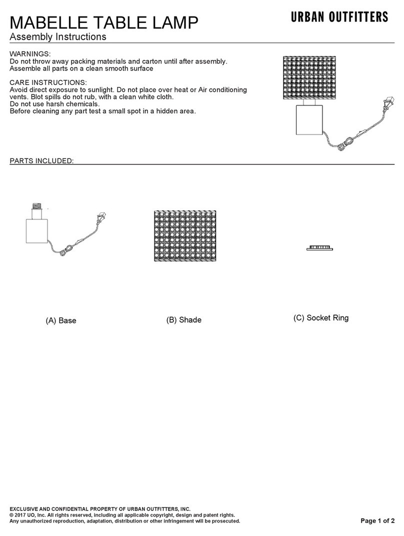
URBAN OUTFITTERS MABELLE Assembly instructions

