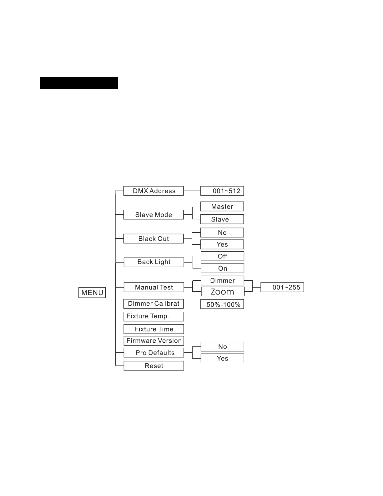
ACME LP-TS100 CW User manual

Theatre spot 100
LP-TS100 CW/WW
User Manual
Please read the instructions carefully before use

TABLE OF CONTENTS
1. Safety Instructions
2. Technical Specifications
3. How to Install the Barn Door
4. How to Set the Fixture
5. How to Control the Fixture
6. DMX 512 Configuration
7. DMX 512 Connections
8. Troubleshooting
9. Fixture Cleaning
1A

1.Safety Introductions
WARNING
Please keep this User Guide for future consultation. If you sell the unit to another user,
be sure that they also receive this instruction booklet.
All fixtures are intact from the manufacturer, please operate follow up the user manual,
artificial fault are not under guarantee repair.
Unpack and check carefully that there is no transportation damage before using the
unit.
The unit is for indoor use only. Use only in a dry location.
Do install and operate by operator.
Use safety chain when fixes the unit. Don’t handle the unit by taking its head only, but
always by taking its base.
The unit must be installed in a location with adequate ventilation, at least 50cm from
adjacent surfaces.
Be sure to locate the unit in a place away from adjacent surfaces at least 1M.
Be sure that no ventilation slots are blocked, otherwise the unit will be overheated.
Before operating, ensure that the voltage and frequency of power supply match the
power requirements of the unit.
It’s important to ground the yellow/green conductor to earth in order to avoid electric
shock.
Maximum ambient temperature TA: 40℃
. Do
higher than this.
Unit’s surface temperature may reach up to 85℃. Don’t touch the housing
bare-handed during its operation, and allow about 15 minutes for cooling the unit down
before replacing bulb or maintenance as it could be very hot.
Don’t connect the device to any dimmer pack.
Make sure there are no flammable materials close to the unit while operating, as it is
fire hazard.
Look over power wires carefully, replace immediately if there is any damage.
Never run on for a long time lest shortening lifespan.
Please read the instructions carefully which includes important
information about the installation, operation and maintenance.
2A

Avoid any inflammable liquids, water or metal objects entering the unit. Once it
happened, cut off the mains power immediately.
Do not operate in dirty and dusty environment, also cleaning fixtures regularly.
Do not allow children to operate the fixture.
Do not touch any wire during operation as there might be a hazard of electric shock.
Avoid power wires twist other cables.
Disconnect mains power before fuse/lamp replacement or servicing.
Replace fuse only with the same type.
In the event of serious operating problem, stop using the unit immediately.
Never turn on and off the unit time after time.
The housing, the lenses, or the ultraviolet filter must be replaced if they are visibly
damaged.
Do not open the unit as there are no user serviceable parts inside.
Never try to repair the unit by yourself. Repairs carried out by unskilled people can lead
to damage or malfunction. Please contact the nearest authorized technical assistance
center.
Disconnect the mains power if the fixture is not used for a long time.
Do use original packing materials once transport it again
Do not look directly at the LED light beam while the fixture is on.
Installation
The unit should be mounted via its screw holes on the bracket. Always ensure that the unit
is firmly fixed to avoid vibration and slipping while operating. Always ensure that the
structure to which you are attaching the unit is secure and is able to support a weight of 10
times of the unit’s weight. Also always use a safety cable that can hold 12 times of the
weight of the unit when installing the fixture.
The equipment must be fixed by professionals. And it must be fixed at a place where is out
of the touch of people and has no one pass by or under it.
Note: the range of mounting height is 0~30 meters.
2. Technical Specifications
◆DMX512 control: 2channels
◆Focus: Automatic focus by DMX control
◆Dimmer: 0 ~ 100%
3A

◆Beam angle: 12 ° ~ 40 °
◆Color Temperature: 5300K-5800K(WW)/3200+200K(VW)
◆Rotating filter and hanger
◆Thermo-optical cooling technology, no noise
Power supply: AC90V ~ 250V 50Hz/60 Hz
Power consumption: 141W
Body temperature: <58 ° C
Working life: 50,000 hours
CRI: Ra=95
Luminous efficiency: 24.3Lm/W (WW)/34.64Lm/W (CW)
Weight: 18.2kgs
Dimension:450.5×406.8×578.0mm
3. How to Install the Barn Door
4A

①Open the spring by hands.
②Insert the barn door into the outside slot from top side.
③Open the barn door, and then fasten the safety cable.
④Insert the barn door into the inside slot from top side.
4. How to Set the Fixture
4.1 Control Panel
1.Fuse (T 3.15 A):
Protect the unit from damage of overcurrent
2.Power Switch:
Turns On/Off the power
3. Power Cable:
To connect to the mains supply
4. DMX output:For DMX512 link, use 5-pin XLR plugs cable to link the next unit
5. DMX input:For DMX512 link, use 5-pin XLR plug cable to input DMX signal
6. Button:
MENU To select the programming functions
DOWN To go backward in the selected functions
UP To go forward in the selected functions
ENTER To confirm the selected functions
7. LED: DMX On DMX input present
MASTER On Master Mode
SLAVE On Slave Mode
SOUND On Sound Mode
5A

8.Display: To show the various menus and the selected functions
9.Safety Ring: Keep the installation safe
10. Ethernet: To transfer the unit’s information to the main controller
4.2 Main Function
To select any functions, press MENU button until the required one is shown on the display.
Select the function by ENTER button and the display will blink. Use DOWN and UP button to
change the mode. Once the required mode has been selected, press ENTER button to
setup or it will automatically return to the main functions without any change after idling one
minute. Back to the functions without any change press MENU button. The main functions
are shown below:
DMX Address
Select DMX Address, press the ENTER button to confirm, the present address will blink on
the display. Use the UP and DOWN button to adjust the address from 1to 512. Once the
address has been selected, press the ENTER button to setup, to go back to the functions
without any change press the MENU button again. Hold and press the MENU button about
one second or wait for one minute to exit the menu mode.
6A

Slave Mode
Select Slave Mode, press the ENTER button to confirm, present mode will blink on the
display. Use the DOWN and UP button to select the Master mode or Slave mode. Once the
mode has been selected, press the ENTER button to setup, to go back to the functions
without any change press the MENU button again. Hold and press the MENU button about
one second or wait for one minute to exit the menu mode.
Black Out
Select Black Out, press the ENTER button to confirm, present mode will blink on the
display. Use the DOWN and UP button to select the Yes (yes blackout) or No (no blackout)
mode. Once the mode has been selected, press the ENTER button to setup, to go back to
the functions without any change press the MENU button again. Hold and press the MENU
button about one second or wait for one minute to exit the menu mode.
Back Light
Select Back Light, press the ENTER button to confirm, present mode will blink on the
display. Use the DOWN and UP button to select the On (Led on) or Off (Led off) mode.
Once the mode has been selected, press the ENTER button to setup, to go back to the
functions without any change press the MENU button again. Hold and press the MENU
button about one second or wait for one minute to exit the menu mode.
Manual Test
Select Manu Test, press the ENTER button to confirm, present mode will blink on the
display. Use the DOWN and UP button to select the Dimmer or Zoom. Once the mode has
been selected, press the ENTER button to setup, use the DOWN and UP button to change
the value (0~255). Once the mode has been selected, press the ENTER button to setup, go
back to the functions without any change press the MENU button again. Hold and press the
MENU button about one second or wait for one minute to exit the menu mode.
Dimmer Calibrat
Select Dimmer Calibrat, press the ENTER button to confirm, the present mode will blink
on the display. Use the UP and DOWN button to adjust the value from 50% to 100%. Once
selected, press the ENTER button to setup, to go back to the functions without any change
press the MENU button again. Hold and press the MENU button about one second or wait
for one minute to exit the menu mode.
7A

Fixture Temp.
Press the MENU button up to when the Fixture Temp. is blinking on the display. Pressing
ENTER button and the display will show the temperature of the unit. To go back to the
functions press the MENU button again. Hold and press the MENU button about one second
or wait for one minute to exit the menu mode.
Fixture Time
Press the MENU button up to when the Fixture Time is blinking on the display. Pressing
ENTER button and the display will show the number of working hours of the unit. To go back
to the functions press the MENU button again. Hold and press the MENU button about one
second or wait for one minute to exit the menu mode.
Firmware Version
Press the MENU button up to when the Firmware version is blinking on the display.
Pressing ENTER button and the display will show the version of software of the unit. To go
back to the functions press the MENU button again. Hold and press the MENU button about
one second or wait for one minute to exit the menu mode.
PRO Defaults
Press the MENU button to show PRO Defaults on the display. Press the ENTER button and
the display will blink. Use the DOWN and UP button to select the Yes (run built-in program
to set the fixture to PRO Defaults settings) or No. Press the ENTER button to setup, to go
back to the functions without any change press the MENU button again. Hold and press the
MENU button about one second or wait for one minute to exit the menu mode.
Reset
Press the MENU button up to when the Reset is blinking on the display. Pressing ENTER
button and all channels of the unit will return to their standard position.
5. How to Control the Unit
You can operate the unit in two ways:
1. By master/slave built-in preprogram function
2. By DMX controller
No need to turn the unit off when you change the DMX address, as new DMX address
setting will be affected at once. Every time you turn the unit on, it will show “LP-TS100” on
8A

the display and move all the motors to their ‘home’ position. After that the unit will be ready
to receive DMX signal or run the built in programs.
5.1 Master/Slave Built In Preprogrammed Function
By linking the units in master/slave connection, the first unit will control the other units to
give an automatic, synchronized light show. This function is good when you want an instant
show.
5.2 DMX Controller
Use universal DMX controller to control the units, you have to set DMX address from 1 to
512 channels so that the units can receive DMX signal.
Press the MENU button up to when the “LP-TS100" showing on the display. Pressing
ENTER button and the display will blink. Use DOWN and UP button to change the DMX512
address. Once the address has been selected, press and keep ENTER button pressed up to
when the display stops blinking or storing automatically one minute later. To go back to the
functions without any change press the MENU button again. If you use please refer to the
following diagram to address your DMX512 channel for the first 4 units.
2 channels:
6. DMX512 Configuration
Channel mode(2channels)
9A

7. DMX512 Connections
The DMX512 is widely used in intelligent lighting control, with a maximum of 512 channels.
1. Connect the fixture together in a “daisy chain” by XLR plug cable from the output of the
fixture to the input of the next fixture. The cable cannot be branched or split to a “Y”
cable. Inadequate or damaged cables, soldered joints or corroded connectors can
easily distort the signal and shut down the system
2. The DMX output and input connectors are pass-through to maintain the DMX circuit
when one of the units’ power is disconnected.
3. At last fixture, the DMX cable has to be terminated with a terminator to reduce signal
errors. Solder a 120-ohm 1/4W resistor between pin 2(DMX-) and pin 3(DMX+) into a
3-pin XLR-plug and plug it in the DMX-output of the last fixture.
4. Each lighting fixture needs to have an address set to receive the data sent by the
controller. The address number is between 0-511 (usually 0 & 1 are equal to 1).
5. 5 pin XLR connectors
5 pin XLR: Pin 1: GND, Pin 2: Negative signal (-), Pin 3: Positive signal (+),
Pin4/5: not used
10A

8. Troubleshooting
Following are a few common problems that may occur during operation. Here are some
suggestions for easy troubleshooting:
A. The fixture does not work, no light
1. Check the connection of power and main fuse.
2. Measure the mains voltage on the main connector.
B. Not responding to DMX controller
1. DMX LED should be on. If not, check DMX connectors, cables to see if link properly.
2. If the DMX LED is on and no response to the channel, check the address settings and
DMX polarity.
3. If you have intermittent DMX signal problems, check the pins on connectors or on PCB
of the fixture or the previous one.
4. Try to use another DMX controller.
5. Check if the DMX cables run near or run alongside to high voltage cables that may
cause damage or interference to DMX interface circuit.
C. One of the channels is not working well
1. The stepper motor might be damaged or the cable connected to the PCB is broken.
2. The motor’s drive IC on the PCB might be out of condition.
9. Fixture Cleaning
The cleaning of internal must be carried out periodically to optimize light output. Cleaning
frequency depends on the environment in which the fixture operates: damp, smoky or
particularly dirty surrounding can cause greater accumulation of dirt on the fixture’s optics.
Clean with soft cloth using normal glass cleaning fluid.
Always dry the parts carefully.
Clean the external optics at least every 20 days. Clean the internal optics at least every
30/60 days.
11A

Innovation, Quality, Performance
12-
This manual suits for next models
1
Table of contents
Other ACME Home Lighting manuals