Felo FW-06 User manual
Service Manual
Electric
Motorcycle
Preface
This manual was prepared by FELO Technology(Shanghai) Co., Ltd. for the purpose of the spot inspection and
motorcycle maintenance by after-sales service personnel of FELO dealers. Although this manual does not cover
all aspects of maintenance, it does contain general information on spot inspection and basic maintenance of the
motorcycle. The purpose of this manual is to ensure that the driver can ride the motorcycle safely and comfortably
through proper maintenance of the motorcycle with tools and devices.
• FELO Technology (Shanghai) Co., Ltd. constantly seeks to improve its products. As such the contents and
specifications herein may be changed without prior notice.
• No part of this manual may be reproduced in any form or by any means without the prior permission of FELO
Technology (Shanghai) Co., Ltd.
• ©2022 FELO Technology(Shanghai) Co., Ltd. All rights reserved.
Key information:
Particularly important information is distinguished with the following symbols.
Danger Failure to follow the instructions will result in serious injury or death.
Warning Failure to follow the instructions may result in serious injury or death.
Attention Failure to follow the instructions may result in your injury.
Caution Take special measures to prevent damage to your electric motorcycle
or other property.
FW-06 Service Manual
January 2023 First edition
Replication is prohibited.
FELO Technology(Shanghai) Co., Ltd.
Table of Contents
1 Basic Instructions
Safety precautions ............... 1
Using this manual ............... 3
2 Motorcycle Information
Model ............... 5
Vehicle information ............... 5
3 Technical Information
Technical parameters ............... 7
Wiring of the pulling wire and wiring harness ..............11
4 Spot Inspection and Adjustment
Maintenance schedule ............. 19
Spot Inspection and Adjustment ............. 20
5 Exterior Plastic Parts
Overview of exterior plastic parts ............. 31
Rear-view mirror ............. 32
Windshield ............. 33
Tool box assembly ............. 34
Handlebar shield assembly ............. 36
Head cover panel ............. 37
Front fender assembly ............. 39
Seat bucket assembly ............. 40
Passenger seat assembly ............. 42
Left/right tail lining assembly ............. 43
Tail cover panel assembly ............. 44
Passenger seat front cover ............. 46
Rear tail light and seat bucket enclosure assembly .... 47
Mid-section cover panel assembly ............. 49
Left/right guard panel assembly ............. 50
Vent pipe assembly ............. 54
Battery pack left/right cover assembly ............. 56
Rear mud guard ............. 58
License plate holder assembly ............. 59
6 Power system
Reduction gearbox ............. 61
Motor assembly ............. 65
7 Body Structure
Front wheel ............. 69
Front wheel speed sensor ............. 71
Rear wheel ............. 72
Front brake ............. 74
Rear brake ............. 77
Handlebar ............. 80
Steering column ............. 82
Front fork ............. 83
Head support ............. 85
Side stand ............. 86
Main, auxiliary footrest ............. 87
Rear shock absorber ............. 88
Upper rocker arm ............. 89
Lower rocker arm ............. 90
8 Electric system
EV (Electric vehicle) system ............. 91
OBD and port model ............. 93
VCU (Vehicle Control Unit) ............. 97
MCU (Motor Control Unit) ............. 99
ICM (Instrument Cluster Module) ........... 101
Battery/charging system ........... 103
DC-DC ........... 106
Lighting system ........... 108
Other components ............115
Smart key ........... 123
ABS System ........... 125
9 Appendix
Schematic diagram of the electrical principles .......... 129

MEMO
Service Manual 1
1 Basic Instructions
Safety precautions
■For the safety of the motorcycle owner
Proper repair and maintenance is crucial for the safety of the motorcycle and its owner. Any error or negligence in
motorcycle maintenance may cause a malfunction during the motorcycle's operation, and this may in turn cause
damage to the motorcycle or personal injuries.
Warning
●Improper repair or maintenance may pose a safety risk; your customer may suffer from
serious injuries or even death as a result.
●Please follow the procedures and precautions specified in this manual carefully.
■For your safety
Because this manual was prepared for professional maintenance/service personnel only, we will not provide the
warnings relating to basic safety rules for repair/maintenance workshop (e.g. wearing gloves when handling heated
parts). If you have not received any safety training provided by the repair/maintenance workshop, or you are not
confident in your knowledge on safe maintenance operations, we recommend you do not attempt to carry out any
procedure described in this manual.
Some of the most important safety precautions in this manual are given below. However, we cannot cover all
dangers that may occur during repair or maintenance. You alone will determine whether such maintenance or repair
is to be carried out.
Warning
●Failure to properly follow the instructions and precautions below may cause serious injuries
or even deaths.
●Please follow the procedures and precautions specified in this manual carefully.
■Instructions on how to operate this motorcycle
Warning
●Before inspecting or repairing (removing/installing) components, always turn off the main
switch and remove the battery.
●To prevent electric shocks, always wear safety protection gears, and use insulation tools
when inspecting or repairing components .
●During such operation, do not carry any metal objects with you.
●Do not work on slippery floors or under the rain.
●The battery electrolyte may cause blindness or injuries. Therefore take extra care when
operating the motorcycle. If your eyes or skin comes into contact with electrolyte , please
immediately flush the area with plenty of water and have it examined by professionals.
Do not use a high-voltage water gun when washing your motorcycle, the high-voltage water may cause a
malfunction in moving or electrical components of your motorcycle.

Basic Instructions
2 Service Manual
■Important safety precautions:
When inspecting and repairing the high-voltage system, please follow the instructions below.
●When carrying out repair or maintenance of the motorcycle, please always wear safety protection gears, and
use insulation tools. Please always check safety protection gears and insulation tools before using.
●When carrying out any high-voltage work, please indicate on the motorcycle that such work is being carried out
to ensure the safety of other people.
Make sure that you clearly understand all safety rules of the repair/maintenance workshop, wear proper clothes and
use safety devices. The following need extra attention when carrying out any maintenance work:
●Before starting any work, please read all instructions in the manual, and ensure that you have all necessary
tools to replace or repair components so as to safely and fully complete your work.
●When you carry out hammering, drilling, grinding or prying operations, or work in the vicinity of high-voltage air
or fluids, springs, or other energy storage components, you need to wear qualified safety glasses, goggles, or
face mask during the entire operating process to protect your eyes.
●Hot or sharp components, may cause serious burns or cuts. Therefore, when necessary, you need to use other
protection gears such as gloves or safety boots.
●If you need to raise your motorcycle for maintenance, please use a jack or special base. Any time you raise
your vehicle, make sure it is always securely supported.
Special tools:
To replace non-universal parts, you should carefully and properly use the tools recommended by our company.
Special parts:
When replacing parts, please use the brands specified by our company. If you use a brand other than our specified
brands, it may harm the part's performance, thus severely shortening the service life of your motorcycle.

Basic Instructions
Service Manual 3
Using this manual
■Symbols
These symbols used in this manual indicate specific maintenance and repair procedures. If there is any need
for additional information relating to these symbols, such information will be provided in the corresponding text
specifically without use of the symbols.
Disassembling procedure
Components to be disassembled before carrying
out the operation in the main diagram
Standard parts
Lubrication Tighten to the specified torque
Adjust or check parts Measure parts
Removal/installation Parts replacement
Apply the lubricant Apply thread locker
Apply the sealant Measure the current
Measure the voltage Measure the resistance

MEMO
4 Service Manual
Service Manual 5
2 Motorcycle Information
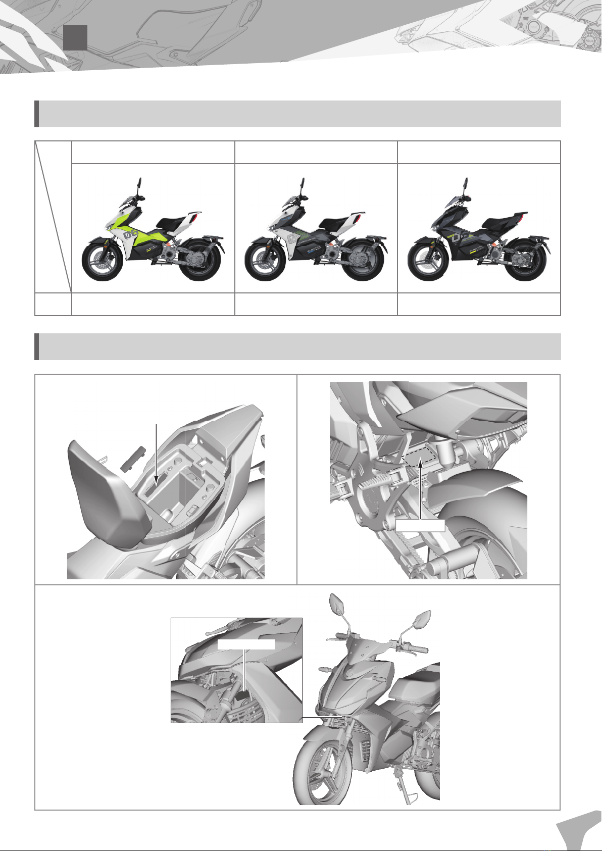
Model
Classic Sci-Fi Green Graffiti Space Grey Obsidian Black
Model FW06-01 FW06-02 FW06-03
Vehicle information
Chassis number
Motor model
Product label

MEMO
6 Service Manual
Service Manual 7
3 Technical Information
Technical parameters
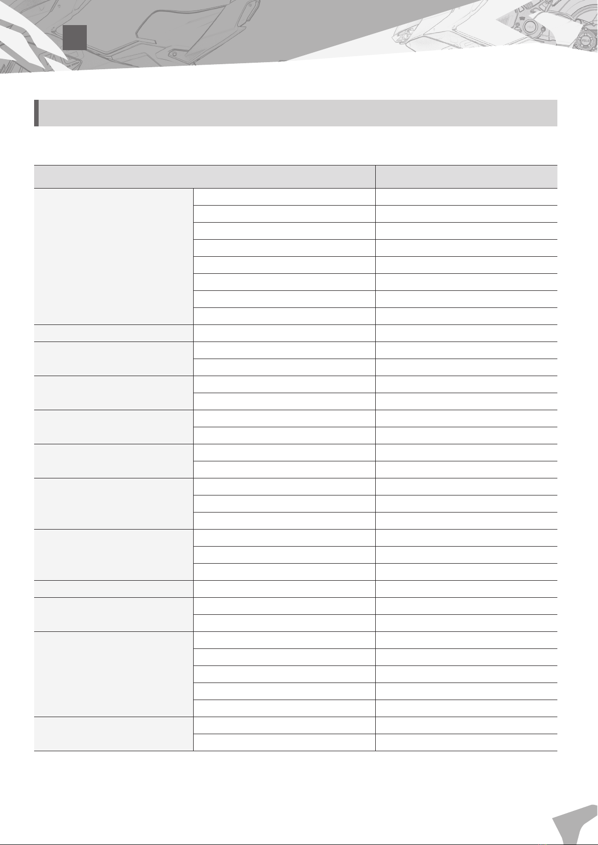
■Main parameters
Items Specification
Size
Total length 1830 mm
Total width 755 mm
Total height 1095 mm
Wheel base 1240 mm
Saddle height 800 mm
Ground clearance 162 mm
Curb weight 125 kg
Maximum load 150 kg
Chassis Chassis type Steel tube chassis
Front wheel Front tire dimension 110/80-14
Cold tire pressure 200 kPa
Front shock absorber Spring free length 438±3 mm
Liquid volume 57- 59 mL
Rear wheel Rear tire dimension 140/70-14
Cold tire pressure 225 kPa
Rear shock absorber Spring free length 275±3 mm
Liquid volume 104-106 mL
Front brake system
Front brake Hydraulic single-disc brake
Brake fluid DOT3
Brake disc thickness 4±0.1 mm
Rear brake system
Rear brake Hydraulic single-disc brake
Brake fluid DOT3
Brake disc thickness 4±0.2 mm
Controller Max input current 120 A
Converter Type DC-DC
Output 13.8 V/7 A
Power battery
Type Lithium battery
Voltage 96 V*
Capacity 58 Ah
Total mass 35±1 kg
Single cell configuration 26S1P
Battery Voltage 12 V
Capacity 4 Ah
* Battery operating voltage is 96 V.

Technical Information
8 Service Manual
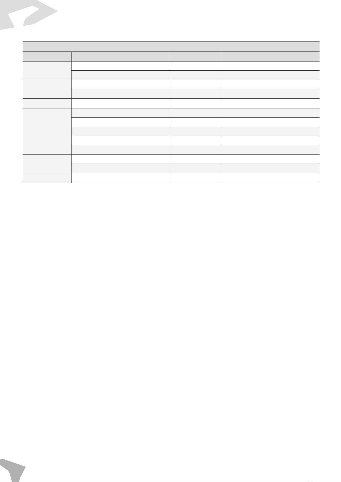
Items Specification
Charger
Charging method CC-CV
Input 100-240 Vac
Output 70-108 V/7.4 A
Cooling method Air cooling
Fuse
Power battery fuse 150 A
DC input fuse 7 A
USB charging fuse 5 A
Power-off switch Power-off switch 63 A
Motor
Motor installation position Central installation
Type Permanent magnet
Rated power 5 kw
Rated voltage 96 V
Cooling method Air cooling
Maximum power 10 kw
■Torque
Body torque
Items Screw specification/model Tightening torque (N·m)
Steering rod
assembly
Steering rod and Lower mount M10*1.25 45
Front riser
Lock nut with four
openings(Ø25-1) 58*
Octagonal lock nut (Ø25- 1) 58
Upper mount M8*1.25 27
Wheel system
Front wheel M10*1.25 40
Rear wheel M16*1.5 120
Suspension system
Front left and right shock
absorber M10*1.25 40
Rear shock absorber M10*1.25 40
Brake system
Front disc brake M8*1.25 35
Rear disc brake M8*1.25 35
Front brake caliper M10*1.25 35
Rear brake caliper M8*1.25 22
Motor lifting
installation
Rocker arm installation M10*1.5 40
Motor installation M8*1.25 22
Rocker arm Rocker arm reduction gearbox
installation M14*2 65
Others
Rear rocker arm rear connection M10*1.5 35
Chassis battery pack front
suspension M10*1.25 40
* A torque of 58 N-m is used to lock the lock nut with four openings counterclockwise, and a torque of 3-5 N-m is used to lock the
column clockwise.

Technical Information
Service Manual 9
Universal torque
Items Tightening torque (N·m)
M4 Bolt, nut 2-4
M5 Bolt, nut 3.5-6
M6 Bolt, nut 7-14
M8 Bolt, nut 18-30
M10 Bolt, nut 30-45
M12 Bolt, nut 50-60
M14 Bolt, nut 60-80
M4 Self-tapping screw 0.5-1.5
M5 Self-tapping screw 1-3
■Unit symbol comparison table
Unit name Unit symbol Unit name Unit symbol
Kilogram Kg Newton N
Gram gKilowatt kW
Degree °Kilowatt hour kW·h
Newton meter N·m Hertz Hz
Kilopascal kPa Temperature in
Celsius °C
Kilogram force
per square
meter
kgf/m2Ampere A
Rotation per
minute r/min Milliampere mA
Meter mVolt V
Centimeter cm Ohm Ω
Kilometer per
hour km/h Liter L
Quart qt Milliliter mL
Pound lb Ounce oz
Mile per hour mph Millimeter mm
Degree in Fahr-
enheit °F
Technical Information
10 Service Manual
■Table of Conversion of Measurement Unit
Metric unit to Imperial unit
Category Metric unit Multiplier Imperial unit
Weight kg 2.2 lb
g 0.04 oz
Torque N·m 0.72 ft·lb
N·m 8.68 in·lb
Speed km/h 0.62 mph
Distance
km 0.62 mi
m 3.28 ft
m 1.094 yd
cm 0.4 in
mm 0.04 in
Volume mL 0.04 oz
L 0.88 qt
Temperature °C 9/5 + 33.8 °F
Note: Use method
Metric unit Multiplier Imperial unit
**kg × 2.2 = **lb
2 kg × 2.2 = 4.4 lb
Technical Information
Service Manual 11
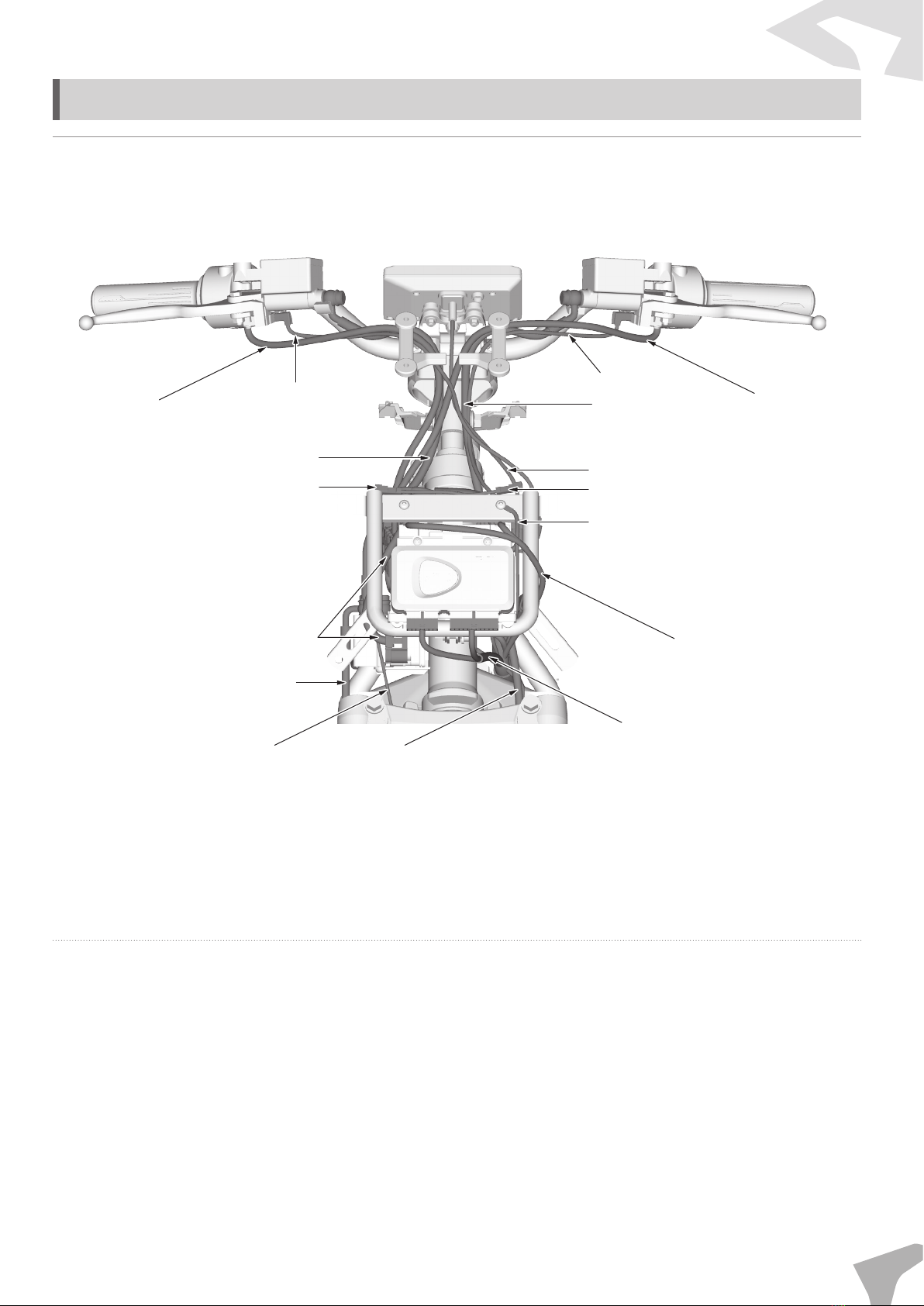
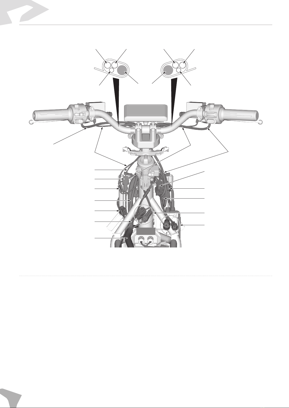
Wiring of the pulling wire and wiring harness
Right combination
switch cable
Right brake signal
cable
Front brake upper oil pipe
Front right turning signal light cable (blue)
ABS connector cable
Front brake lower oil pipe
Wheel speed sensor cable Rear brake oil pipe
VCU connector cable
Battery cable
Ground cable
Front left turning signal light cable (orange)
Meter cable
Rear brake oil pipe
Left brake signal cable
Left combination
switch cable
Technical Information
12 Service Manual
Left combination switch cable
Left combination switch cable
Left brake signal cable
Meter cable
Meter connector
Rear brake oil pipe
Headlight connector
Cushion pulling wire Charging connector
Handlebar lock connector
Left combination
switch connector
Turning handle connector
Right combination
switch connector
Right combination
switch cable
Right brake
signal cable
Main wiring harness
Left/right brake signal cable
connector
Rear brake oil pipe
Front brake
oil pipe Right combination switch cable
Right brake signal cable
Left brake signal cable
Handlebar
Technical Information
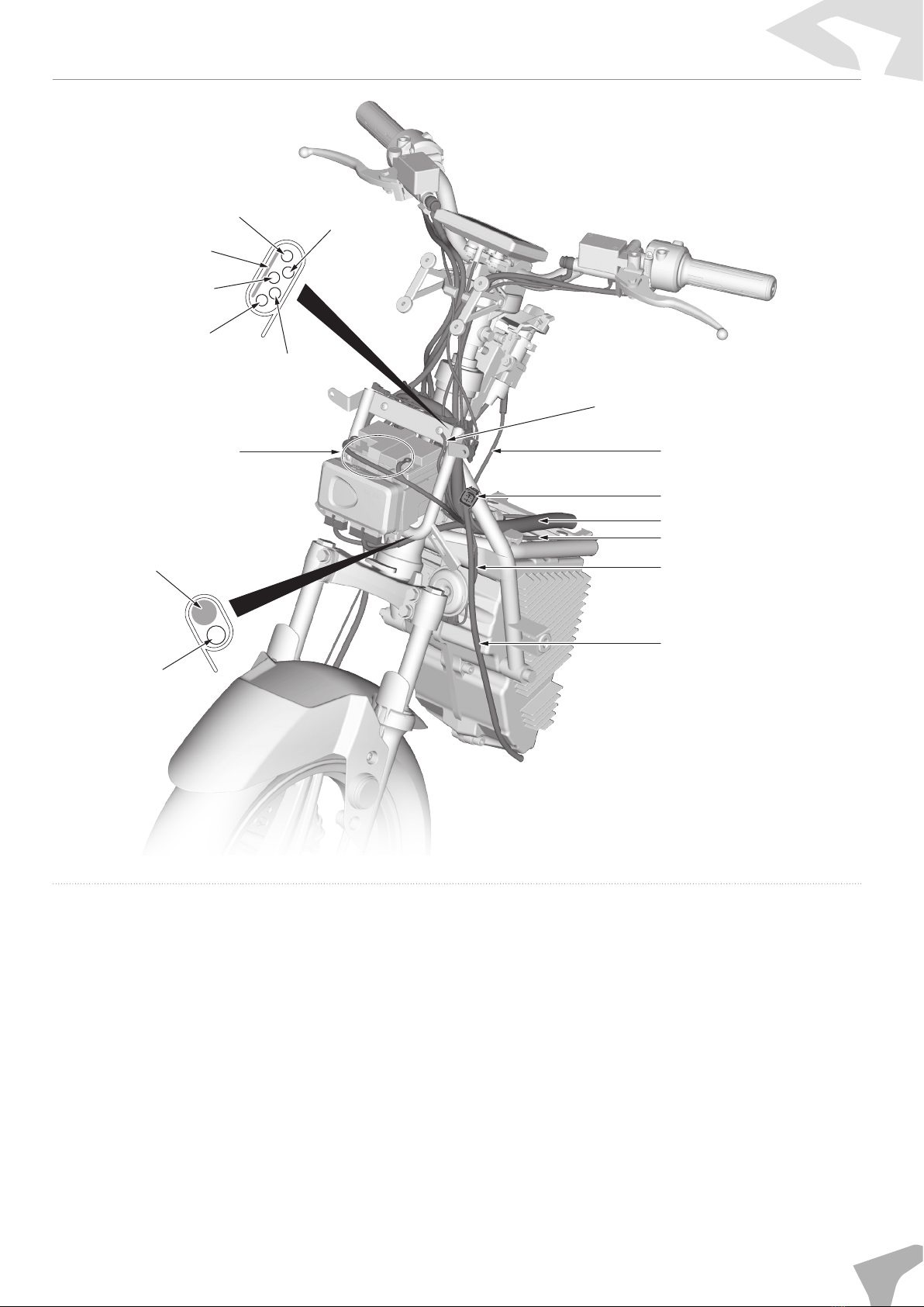
Service Manual 13
Front turn signal light cable
Head support
Brake signal cable
Speed sensor cable
Meter cable
Battery cable
Chassis
VCU connector cable
Rear brake oil pipe
Horn cable
Cushion pulling wire
Main wiring harness
Headlight connector
Cushion pulling wire
Ground cable
USB connector cable

Technical Information
14 Service Manual
Main wiring harness
Front brake oil pipe
(ABS lower pump oil pipe)
Speed sensor cable
Front brake oil pipe
ABS connector cable
Charging cable
Head support
Left/right combination
switch cable
Turning handle cable
Speed sensor cable

Technical Information
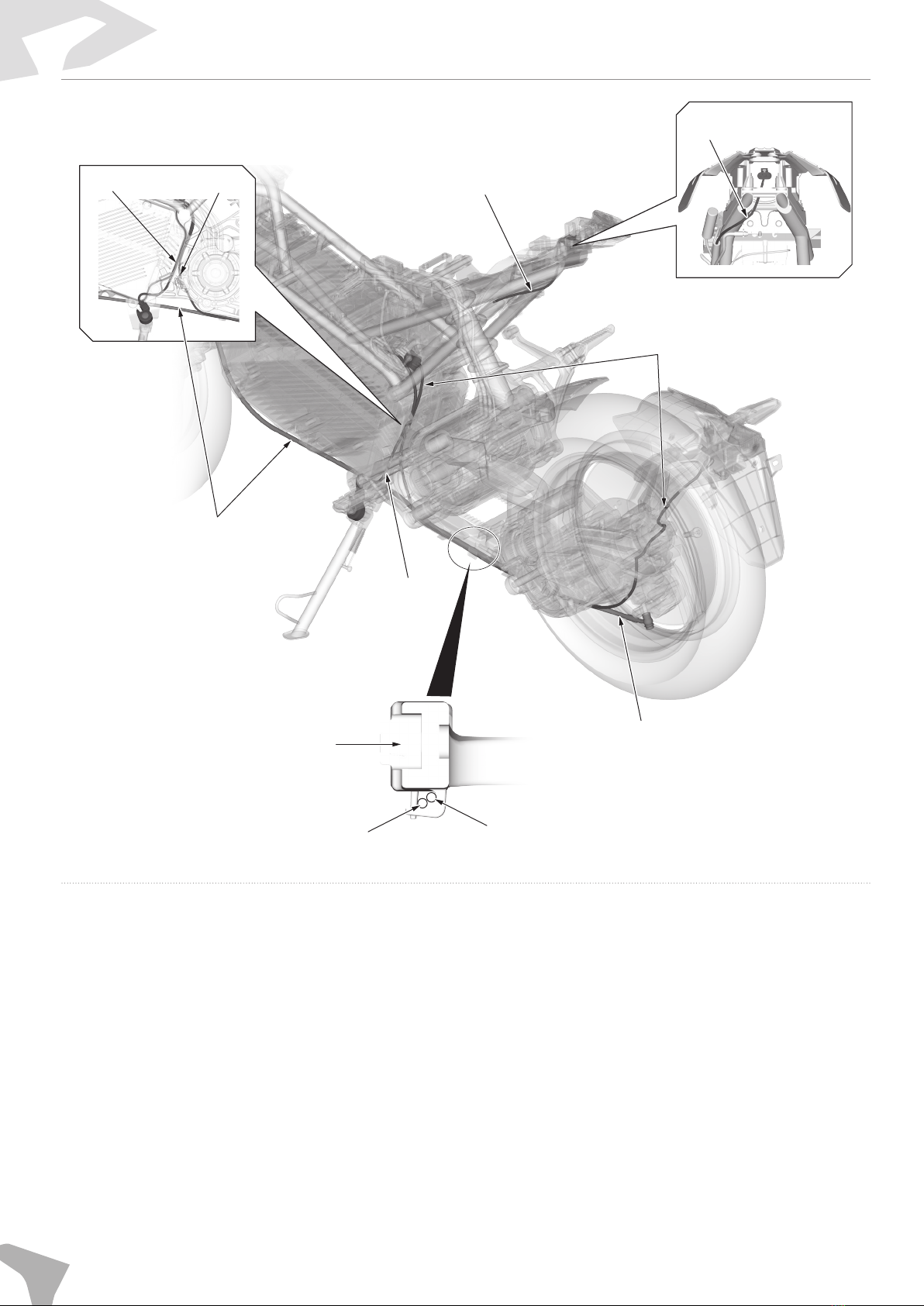
Service Manual 15
Main wiring harness
Rear brake oil pipe
Headlight cable
DC-DC cable
Resolver plug-in cable
OBD cable
Tail light cable
Air switch cable
MCU plug-in cable
Chassis
Chassis
Chassis
Chassis
Chassis
Tail light cable
Cushion
pulling wire
Fuse cable
Main wiring
harness
Cushion pulling wire
Side stand cable
License plate
light cable
Auxiliary discharge plug-in
Battery pack middle support
Cushion pulling wire
Cushion
pulling wire
Main wiring
harness
Technical Information
16 Service Manual
Side stand cable
License plate light cable
Tail light cable
Tail light cable
License plate light cable
Rear brake oil pipe
Rear brake oil pipe
License plate light cable
Side stand cable
Rear brake oil pipe
Lower rocker arm
Other manuals for FW-06
1
Table of contents
Other Felo Motorcycle manuals


