Fermax DUOX User manual

DUOX VIDEO AMPLIFIER
QUICK START GUIDE

3DUOX VIDEO Cod. 970107I V09_17
SETTINGS
1. PANEL SETTINGS
3. ENCODING PANELS*
Whenever there is more than one panel, you must program the number of panels.
2. HOW TO CONFIGURE THE MASTER PANEL
Press the SW1 button rapidly 3 times in a row.After 2 seconds, you will hear a confirmation tone, and
the master panel will be activated. This is necessary if you need to programme the home terminal
(monitor). Deactivate the MASTER panel by pressing the SW1 button 3 times in a row.
4. CAMERA FOCUS / LOCK RELEASE ACTIVATION TIME*
To adjust the camera image or adjsut the lock-release activation time.
*Note:
See Voice assisted configuration in button panels. See Configuration Table in Direct Panel.
Panel Connectors:
B,B: DUOX Bus: telephone/monitors power, data, audio and
video.
C, NO, NC: Relay contacts 2A@30Vdc (lock-release
connection).
+12: 12 Vdc-250mA output (maximum 500mAfor 100 seconds).
BS, -: entrance hall button.
S, -: door sensor input.
+, GND: not available Future versions.
P1, P2: Button Connection
JP1: Camera leds
LEDS ON. On when the
camera is activated.
LEDS OFF. always off
Selecting the language1
of the "door open" message
Audio Settings
of the Monitor, panel and open door.
Microphone Connection
Amplifier Version
SW1 Button
ON ON ON ONON
ON ON ONON
512 3 4 6 512 3 4 6 512 3 4 6 512 3 4 6
512 3 4 6
ON
ON
512 3 4 6
ON
5
512 3 4 6
ON
62
512 3 4 6
ON
63
512 3 4 6
ON
512 3 4 6
11
ON ON ON ON ON ON
21
512 3 4 6
ON
20
512 3 4 6
ON
17
512 3 4 6
ON
512 3 4 6
ON
512 3 4 6
19
12 13 14 16 1815
512 3 4 6 512 3 4 6 512 3 4 6 512 3 4 6 512 3 4 6
ON
22
512 3 4 6
ON
23
512 3 4 6
ON ON
512 3 4 6
ON
512 3 4 6
ON
512 3 4 6
ON ON
512 3 4 6
24 26 27 29
25 28
512 3 4 6 512 3 4 6
ON
512 3 4 6
ON
512 3 4 6
012 3 467 89 10
30 31
512 3 4 6
512 3 4 6 512 3 4 6 512 3 4 6
1'Door open' warning language selection
Spanish English French German Catalonian Valencian Balearic Portuguese Basque Galician
Dutch/
Flemish Greek
Finnish Swedish
TurkishPolish Czech Slovak Chinese Persian/
Farsi Arabic Norwegian Danish Icelandic
Russian Hindi HungarianItalian Hebrew Croatian 31...62
Bell DEACTIVATEDbell
French
(LONG) campana

DUOX VIDEO 4
CONFIGURATION
1. VOICE ASSISTED CONFIGURATION IN BUTTON PANELS
SW1
SW1
ON
B
D
A
C
E
F
PL
Nº
SB
BK
EG
Nº
TYPE
BK
DL1
CN9 TAMPE
CN1 PACK EXTENSION
ALIMENTACION
POWE SUPPLY
18 Vdc
-+
JP1
JP2
-
BS S
CNCNO
B
B+
GND
P2
EXIT
ONE
TO
ONE
CT
+
2
1
ADAPTO
LINE
LEDS
JP2
JP1
COFF
OFF
ON
VIDEO
DUOX
AMPLIFIE
AMPLIFICADO
CN2
C
NC
NO
MIC
AUDIO
LANGUAGE
IDIOMA
BUS
CN3
VE SION
:
18Vdc
P1
SW1
CN9
CN1
SW1 P OG
1. Access configuration by pressing SW1 4 times. The amplifier
sounds the message “CONFIGURATION” and starts the
process.
In order to exit the configuration process you can press and
hold SW1 for 5 seconds otherwise it will exit automatically
after 30 seconds of inactivity.
See diagram.
Language selection of the voice messages through the
Synthesizer. (Languages available: Spanish, English,
French, German, Italian and Portuguese).
2. By pressing SW1, you advance through the different parameters and it speaks: currently
configured parameter and value.
After the message has sounded, you can press any call button to change the value, (you will hear
a BEEP for each press and the value will increase).
After it is entered, you will hear the new value played after 5 seconds of not pressing anything.
When the parameter’s value reaches the highest possible value, you will hear a BOOP and the
value goes to the minimum for that parameter.
3. If the call button is pressed for 5 seconds, a BOOP sounds and the parameter, if a number, is set
to its minimum level and if another value, is reset to the default value.
DIAGRAM

5DUOX VIDEO
Position Adjust Parameter Values [default] Comment
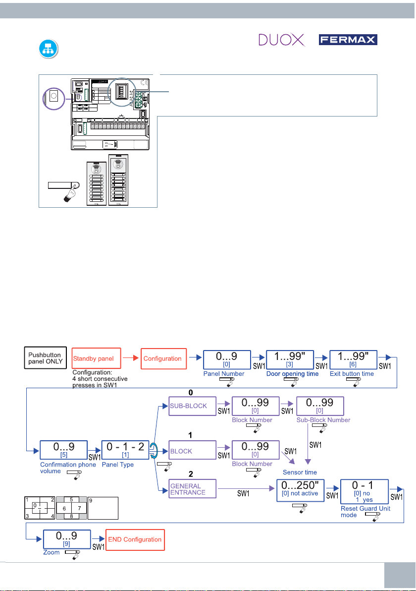
01 Time activ. lock releases 01-99” [03] Relay activation of lock releases from home or access control.
02 Time activ. exit button 00-99” [06] Relay activation of lock releases from exit button (terminals Bs y -)
03 Panel type 0: Sub-Block Configuration of panel type
[1]: Block
2: General Entrance
04 Block Nº 00-99 [00] Block number belonging to the panel
05 Sub-Block Nº 00-99 [00] Sub-block number belonging to the panel
06 Panel Nº 0-9 [0] Panel number
07 Door sensor time 000-250 Maximum time that the door is allowed to remain
[000] inactive open once activated
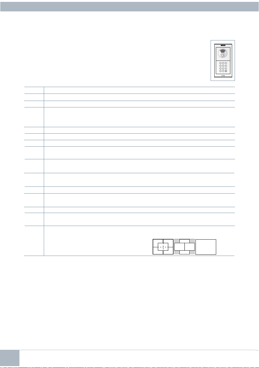
08 Opening code 0000-9999 Opening code from the keyboard. The means of
[0000] inactive entering the code: A + XXXX (4 digits)
09 Programming code 0000-9999 Code to access programming
[4444]
10 MASTER panel [0]: No / 1: Yes Activation of panel as master to programme home terminals
11 Caretaker Mode [0]: No Reset Reset to night mode by entering “1” in this position
1: Reset
12 Monitor Volume 0-9 [5] Adjust the volume of the panel monitor
13 RESET settings [0]: No Reset Return to default settings by entering a “1”
1: Reset in this position
14 Focus the camera 0-9 [9] The choice of the different values 0-9 represent each of
the video screens
0
2
34
1
67
5
8
9
2. CONFIGURATION TABLE IN DIRECT PANEL
You can configure the parameters using the keyboard.
To do this you will need to enter the configuration mode using a programming access
code after pressing ‘A’.
To enter programming:A + 4444 (Default programming access code).
If the code is correct you will hear a confirmation code (beep-beep).
Parameters that can be configured:
987
654
321
AB
0
Configuration of settings
Introduce the two digits of its position, you will hear a beep and then you need to enter the desired value
(1, 2, 3 or 4 digits, depending on the setting). If the value is correct you will hear a confirmation tone (beep-
beep) and the new value will have been saved. If it was incorrect you will hear the error sound (boop).
To leave the programming mode you need to press ‘A’ when introducing the position number of the
menu. It will also automatically exit after 60 seconds without the need to press any key, generating
a beep-beep tone.
Position + Possible values Comment
01...14 (beep) 1, 2, 3 or 4 digits (beep-beep) Digits depending on chosen setting
Examples
09 (beep) 1128 (beep-beep) Change of programming code to 1128
01 (beep) 02 (beep-beep) Change of lock release activation time to 2
seconds

DUOX VIDEO 6
1. INTERNAL WIRING: CALL EXTENSION MODULE CONNECTION Ref. 2441
A IBA
UP
+
-
ON
B
D
A
C
E
F
PL
Nº
SB
BK
EG
Nº
TYPE
BK
DL1
CN9 TAMPE
CN1 PACK EXTENSION
ALIMENTACION
POWE SUPPLY
18 Vdc
-+
JP1
JP2
-
BS
S
C
NCNO
B
B
+
GND
P2
EXIT
ONE
TO
ONE
CT
+
2
1
ADAPTO
LINE
LEDS
JP2
JP1
COFF
OFF
ON
VIDEO
DUOX
AMPLIFIE
AMPLIFICADO
CN2
C
NC
NO
MIC
AUDIO
LANGUAGE
IDIOMA
BUS
CN3
VE SION
:
18Vdc
P1
SW1
CN9
CN1
SW1 P OG
JP3
JP2
2
1
34 8567
11
9
10
1312 1614 15
EF.2441
MODULO EXTENSION 16 LLAMADAS
16 CALL EXTENSION PACK
A IBA
UP
A IBA
UP
A IBA
UP
A IBA
UP
A IBA
UP
1
3
5
7
9
2
4
6
8
12
10
11
14
CP +
-
13
10
14
12
6
8
2
4
5
7
9
1
3
13
11
1a. CONNECTION TO SERVERAL CALL EXTENSION MODULES
(MORE THAN 16 PUSHBUTTONS CONNECTION)
16 EXTENSION CALL PACK
1
EF.2441
43276510981211 151413 16
PACK EXTENSION 16 LLAMADAS
SIGUIENTE/NEXT
ANTE IO /P EVIOUS
LLAMADAS/CALLS
16 EXTENSION CALL PACK
1
EF.2441
43276510981211 151413 16
PACK EXTENSION 16 LLAMADAS
SIGUIENTE/NEXT
ANTE IO /P EVIOUS
LLAMADAS/CALLS
......
17
31
15
19
18
32
16
20
2
4
1
3
Pushbuttons
(17...32)
Pushbuttons
(1...16)
12
To the amplifier
INSTALLATION

7DUOX VIDEO
RESET SETTINGS
a) RESET Mapping (code for call button)
1º To reset the amplifier: remove power supply.
2º While pressing the SW1 button, plug in power supply and continue pressing the SW1 button for
5 seconds. The LED will blink rapidly to indicate that the button mapping has been restored.
b) RESET of settings to factory default values (by keyboard)
With a Direct Panel introduce the numerical values*.
With a Pushbutton Panel you will need to temporarily connect a keyboard (ref. 7439) to enter
numerical values*.
*Note:
See Configuration Table in Direct Panel.
ON
B
D
A
C
E
F
PL
Nº
SB
BK
EG
Nº
TYPE
BK
DL1 CN9 TAMPE
CN1 PACK EXTENSION
ALIMENTACION
POWE SUPPLY
18 Vdc
-+
JP1
JP2
-
BS
S
C
NCNO
B
B
+
GND
P2
EXIT
ONE
TO
ONE
CT
+2
1
ADAPTO
LINE
LEDS
JP2
JP1
COFF
OFF
ON
VIDEO
DUOX AMPLIFIE
AMPLIFICADO
CN2
C
NC
NO
MIC
AUDIO
LANGUAGE
IDIOMA
BUS
CN3
VE SION
:
18Vdc
P1
SW1
CN9
CN1
SW1 P OG
CN1
CN1 CN1
ENT ADA/INPUT
A IVÉE/EINT ITT
UP
SALIDA/OUTPUT
SO TIE/AUSGANG
CN2
MÓDULO TECLADO
KEYPAD MODULE
MODULE CLAVIE
TASTATU MODUL
PUT
NT ITT CN1 CN1
987
654
321
AB
0
CITYLINE Pushbutton panel AMPLIFIER
5 channel cable
The call extension
module can be used.
Detail
Connect the 5 channel cable to
the keyboard (CN1): leave the
pin on the right free.
ON
B
D
A
C
E
F
DL1 CN9 TAMPE
CN1 PACK EXTENSION
ALIMENTACION
POWE SUPPLY
18 Vdc
-+
JP1
JP2
-
BS S
CNCNO
B
B
+
GND CT
CN2
ADAPTO
LINE
LEDS
JP2
JP1
COFF
OFF
ON
PL
Nº
SB
BK
EG
Nº
TYPE
BK
VIDEO
DUOX AMPLIFIE
AMPLIFICADO
+2
1
C
NC
NO
EXIT
MIC
AUDIO
LANGUAGE
IDIOMA
ONE
BUS
CN3
TO
ONE
VE SION
:
18Vdc
SW1
CN9
CN1
SW1 P OG
ENT ADA/INPUT
A IVÉE/EINT ITT CN1
UP
SALIDA/OUTPUT
SO TIE/AUSGANG
CN2
MÓDULO TECLADO
KEYPAD MODULE
MODULE CLAVIE
TASTATU MODUL
987
654
321
AB
0
6 channel cable
SKYLINE Pushbutton panel AMPLIFIER
ref. 7439 ref. 7439

DUOX VIDEO 8

Avd. Tres Cruces, 133
46017 Valencia
Spain
Contact: [email protected] / www.fermax.com/contact
For extended information, visit www.fermax.com
Other manuals for DUOX
13
Table of contents
Other Fermax Amplifier manuals