FERPINTA Herculano H2RS User manual

// OPERATOR’S MANUAL
SPREADERS •H2RS | H2RS-RG | H4R
EN


ÍNDEX
INTRODUCTION____________________________________________
GENERAL MODEL IDENTIFICATION___________________________
EQUIPEMENT IDENTIFICATION______________________
AXLE IDENTIFICATION _____________________________
SIMBOLOGY_______________________________________________
EC” DECLARATION OF CONFORMITY _______________
SAFETY ALERTS ____________________________________
GENERAL SAFETY RULES_____________________________________
STARTING WORK___________________________________________
SAFETY____________________________________________________
WARNING LABELS POSITION ________________________________
TECHNICAL SPECIFICATION_________________________________
TRANSMISSION CARDAN ___________________________________
INITIAL COUPLING TO TRAILER_______________________________
HYDRAULIC SYSTEMS_______________________________________
HYDRAULIC SYSTEM CONNECTIONS ________________
HYDRAULIC DRAWBAR_____________________________
HYDRAULIC BRAKING SYSTEM______________________
SELF-STEERING AXLE SYSTEM _______________________
FORCED STEERING AXLE SYSTEM____________________
HYDRAULIC REAR DOOR___________________________
HYDRAULIC MOVING FLOOR_______________________
PNEUMATIC BRAKING SYSTEM_______________________________
PARKING / EMERGENCY BRAKE SYSTEM______________________
GENERAL CARE____________________________________________
4
5
5
5
6
6
6
7
9
10
11
13
15
16
17
17
17
18
21
22
25
26
27
28
29
SIGNALING ____________________________________________
CONNECTION AND LIGHTNING SCHEMES ________________
SUSPENSION ___________________________________________
OPCIONALS____________________________________________
DEVICES TO PREVENT UNAUTHORIZED USE ________________
MAINTENANCE AND SERVICE____________________________
TIMETABLE - MAINTENANCE AND SERVICE________________
MALFUNTIONS / POSSIBLE SOLUTIONS____________________
EQUIPMENTS END OF LIFE________________________________
WARRANTY CONDITIONS________________________________
HOW TO ORDER PARTS__________________________________
30
31
33
34
38
39
46
48
50
51
52

OPERATOR’S MANUAL: H2RS | H2RS –RG | H4R
4
INTRODUCTION
Dear Customer,
Congratulations on your choice, as you have just purchased equipment built with high technology and
strict quality standards.
All our efforts are put into research, innovation, development and improvement of this product, so that you
can take advantage of the quality, performance, and work in safety.
This manual was created to help you and to advise about safety, maintenance and how to use the
equipment. Thereby, you will be able to use it with confidence in order to ensure a good performance.
Please start by reading it carefully in order to become familiar with all the equipment and the most
important aspects of safety, its usage as well as other useful information.
Anyone operating, maintaining, or transporting this equipment must read and thoroughly understand the
instructions outlined in this manual before starting to work.
Please take note of all issues related to safety and instructions included in this manual, complying with them
in order to guarantee your safety and others safety.
Please keep the manual in an accessible and safe place, so that you can refer to it whenever necessary.
It is essential that this equipment is inspected periodically, that it is maintained and fitted with suitable spare
parts.
HERCULANO will provide you with any necessary support, solving problems or clarifying questions that you
may have when using the equipment.
HERCULANO –ALFAIAS AGRÍCOLAS S.A.
3720-051 Oliveira de Azeméis
PORTUGAL

OPERATOR’S MANUAL: H2RS | H2RS –RG | H4R
5
GENERAL MODEL IDENTIFICATION
•Improves safety in the event of an accident
•Minimizes the consequences of a rear-end
collisions;
•Prevents underride accidents of the rear-end of
vehicle;
300x60 AXLE
LABEL
ID1
ID2
ID3
ID4
EB/AMB
MF ou
MFG
300x60V
5886
36102919
400x80 AXLE
EB / AMB
FF
400x80V
7848
36103119
EB / AMB
FF
400x80V
6867
36106718
ADR
TG or
TC
408E
7848
36105319
406x120 AXLE
ADR
VC
412E
11282
36106111
EB/AMB
6J
406x120V
11282
36110811
406x140 AXLE
EB/AMB
WC
406X140V
414E
12263
36110512
420x180 AXLE
EB/AMB
8K
420x180V
12753
36110712
ADR
XC
4218E
10791
36106616
ADR
XC
4218E
12753
36106511
EQUIPMENT IDENTIFICATION
The plates can be metallic or stickers. They enclose
important information as they identify the type of
axle and in case it is needed a repair or
replacement of parts.
APROVED UNDERRUN BAR
- Category
- Homologation No.
- Identification No.
- Maximum load
Technically allowable
- Load on the device
- Load on the 1st axle
- Load on the 2nd axle
- Load on the 3rd axle
ID TAG PLATE
IDENTIFICATION NO.
TX7 ********* * * * * *
WMI
Code
Vehicle
Id.
Serial
manufatur
e NO.
AXLE IDENTIFICATION
The information of the serial number and type of
axle is stamped on the identification plate located
at the following place:
Example of an (ADR) axle identification sticker.
The trailer is equipped with homologated bumpers.
Axle identification plate
(or)

OPERATOR’S MANUAL: H2RS | H2RS –RG | H4R
6
SIMBOLOGY
EC DECLARATION OF CONFORMITY
This equipment complies with the requirements of the European Parliament and Council Directive,
2006/42/EC, of 17 May 2006, transposed into Portuguese law by Decree-Law No. 103/2008 of 24 June
2008.
The EC Declaration of Conformity is attached to the Trailer User Manual.
SAFETY ALERTS
DANGER!
Failure to comply with this signal may cause damage
to the equipment and cause serious injuries to people,
endangering your own life.
•
All "Danger" instructions must be followed and
respected!
WARNING!
If you do not respect this signal, you will be subject to
severe injuries and possible damage to the
equipment.
•
All "Warning" instructions must be followed
and respected!
INFORMATION
Additional useful information goes next these symbols!
•
Please read all the points with additional
information carefully since they are useful to
become familiar with your equipment.
CAUTION!
The special caution signals go next this symbol!
•
Please take the necessary precautions and
follow the recommended operating
instructions to avoid problems or accidents.
MAINTENANCE!
Iconography used for Maintenance and/ or Cleaning!
•
Carefully carry out the recommended
maintenance and cleaning procedures to extend
the equipment's service life and keeping the safety
conditions.
LUBRIFICATION!
The Lubrication and Oil Level Replacement
Instructions go next to this symbol!
•Please pay attention to the lubrication points and
periodicity, or the replacement of grease or oil
level. Failure to follow this instruction may
jeopardize the proper performance of the
equipment.

OPERATOR’S MANUAL: H2RS | H2RS –RG | H4R
7
GENERAL SAFETY RULES
•H2RS | H4R spreader’s, were developed for the
public and agricultural market. They must not be
used for any other purposes than those
mentioned, as they could jeopardize your safety
and that of third parties.
•Before carrying out any maintenance or a repair
operation on the equipment that requires tipping,
make sure that the vehicle is properly stabilized
and on flat ground. Switch off the engine and
properly put the tractor’s brake on before
proceeding with any operation that may
jeopardize your safety and others' safety.
•Serious fatal errors can occur if precautions are
not taken and safety measures are not
respected.
•Equipment must only be repaired, and damaged
components only replaced, by certified or
qualified people for this purpose.
•Always use the most suitable tools as well as
personal protective equipment during vehicle
maintenance operations and repairs.
•Make sure that all spare parts and components
are compatible with the equipment and that
they do not affect the safety of the vehicle, your
safety, or others' safety.
•It is recommended that you always use original
replacement parts / spare parts from the
manufacturer to ensure that they fit properly
and that they do not affect the vehicle’s
structural capacity or safety.
•Make sure that you carry out all inspections and
services on your equipment at specific time
ranges.
GENERAL SAFETY RULES
Changes to the Trailer:
The chassis structure, wheels, braking system, hydraulic/pneumatic system and electrical system must not be
modified or reconverted, as they are important safety elements and, if they are altered, they may jeopardize
the safety of the equipment.

OPERATOR’S MANUAL: H2RS | H2RS –RG | H4R
8
GENERAL SAFETY RULES
•Whenever carrying out coupling / decoupling of
the equipment, it is strictly forbidden to stand
between the tractor and trailer unless they are
properly immobilized with the parking brake on,
if applicable, and with wheel chocks.
•When it is necessary to couple the trailer to the
tractor, please stand in one side of the tractor
and make sure that you properly fit the safety
pins or chains.
•Always wear suitable clothes and shoes,
avoiding the use of loose or baggy clothing.
•Do not allow people to remain or ride in the
trailer.
•Always check the pressure and general
condition of the trailer's and tractor's tires prior to
each use.
•Always comply with your tractor’s towing load
limits.
•Regularly check the general condition of the
hydraulic and pneumatics hoses, if applicable.
Replace them in case they are damaged or
worn out. Replacement hoses must meet the
technical requirements specified by the
manufacturer.
•Check oil levels regularly and keep the
lubrication points properly lubricated with
grease and check if they are not dirty.
•Before starting transportation, check if the
braking system is working properly.
•When driving on public roads, comply with the
rules in force. Always check if the lightning
devices fitted to the rear, side, and front of the
vehicle, work correctly.
•Never carry out maintenance work with the
trailer tipped without first installing the safety
prop between the upper frame and the lower
frame.
•Depending on the characteristics of the
equipment and the type of product loaded,
the total weight of the vehicle under full load
may exceed the Maximum Allowable Mass
regulated in the country in which it travels. In
the case of traffic on public roads, the user must
ensure compliance with the dimensions and
masses defined in the legislation and highway
code applicable in the country. Herculano will
not be held responsible for any consequences
arising from non-compliance with legal
requirements.

OPERATOR’S MANUAL: H2RS | H2RS –RG | H4R
9
STARTING WORK
BEFORE STARTING WORK
BEFORE STARTING THE OPERATION
Before starting work, the operator must be aware
of all the equipment and its functions. Getting to
know the systems after starting to work may be too
late!
The equipment must always be tested before each
operation and before driving on public roads!
Follow the instructions and always keep in mind all
warnings and safety signs included in the manual
and on your spreader.
1. Make sure that all safety equipment is in good
working and maintenance condition.
2. Make sure to keep the joints / lubrication points
properly lubricated with grease. Check oil levels
regularly and check for any looseness in the axles or
damaged bearings.
3. Make sure that the tires are inflated to with the
proper pressure and that they are in good general
condition.
4. Check the tightness of level wheels.
5. Connect the spreader electrical plugs to the tractor
and make sure the electrical system works properly.
6. Ensure the proper functioning of the spreader with
only the accessories / equipment provided.
7. Connect all hydraulic and / or pneumatic sockets (if
applicable) to the tractor.
•Check the hydraulic hoses for wear or
leakage.
•Make sure you connect the hoses correctly.
8. Check the parking brake system as well as the
service brake.

OPERATOR’S MANUAL: H2RS | H2RS –RG | H4R
10
SAFETY
PERSONAL PROTECTIVE EQUIPMENT
It is very important that the operator wears personal
protective equipment daily to minimize the risks of
an accident.
The instructions in this manual are essential, please
always use PPE's - Personal Protective Equipment.
PLEASE WEAR –PROTECTION FOOTWEAR
PLEASE WEAR –PROTECTION GLOVES
PLEASE WEAR –PROTECTION HELMET
PLEASE WEAR –PROTECTION VEST / CLOTHING
WARNING LABELS
Warning stickers are part of the User Manual. Please
follow all procedures, keep the stickers legible and
immediately replace any lost or damaged labels.
Please always read the user manual!
7 AC 001
Danger! Articulated machine!
7 AC 004
Danger! Articulated machine!
7 AC 007
Tire pressure indicator. Inflation pressure varies
depending on the fitted wheel!
7 AC 024
Product check - OK
7 AC 047
0
Lubrication point!
7 AC 082
Danger of dragging!
Power take-off transmission shaft connected to a machine.
7 AC 008
Turn off the tractor!
7 AC 002
Danger of arm dragging!
7 AC 010
Do not climb onto the loading platform if the PTO is connected to the
tractor and the engine is running.
7 AC 014
Power take-off
(When applicablel)
7 AC 022
Power take-off
(When applicablel)
7 AC 104
Indication off wheel and torque tightening!
7 AC 111
Manual valve of the braking system
Min / MED / MAX
(When applicable)
7 AC 124
Warning to adjust the manual valve of the
hydraulic braking system, accordingly to the load
transportation..(WhenApplicablel)
7 AC 124.1
Matching timetable of the hydraulic
function by colour.
7 AC 116
Warning to check the stopcocks on the
steering axles!
(when applicable)
7 AC 118
Warning to check the stopcocks on the steering
axles.
(when applicable)
7 AC 118.1

OPERATOR’S MANUAL: H2RS | H2RS –RG | H4R
11
SAFETY
Warning!
Compatibility of new tires and pressure
regulation.
(When applicable)
7 AC 126.2
Warning to read the instruction Manual and ensure
the AMB/ADR assembly dimension = 250mm
(When applicable)
7 AC 132
Elevation points –Wheel change
7 AC 134.1
7 AC 134.2
Warning to adjust the electric valve of the
braking system, according to the load
transportation needs (When applicable)
7 AC 135
Warning!
Lubrication and Oil Change Periodicity
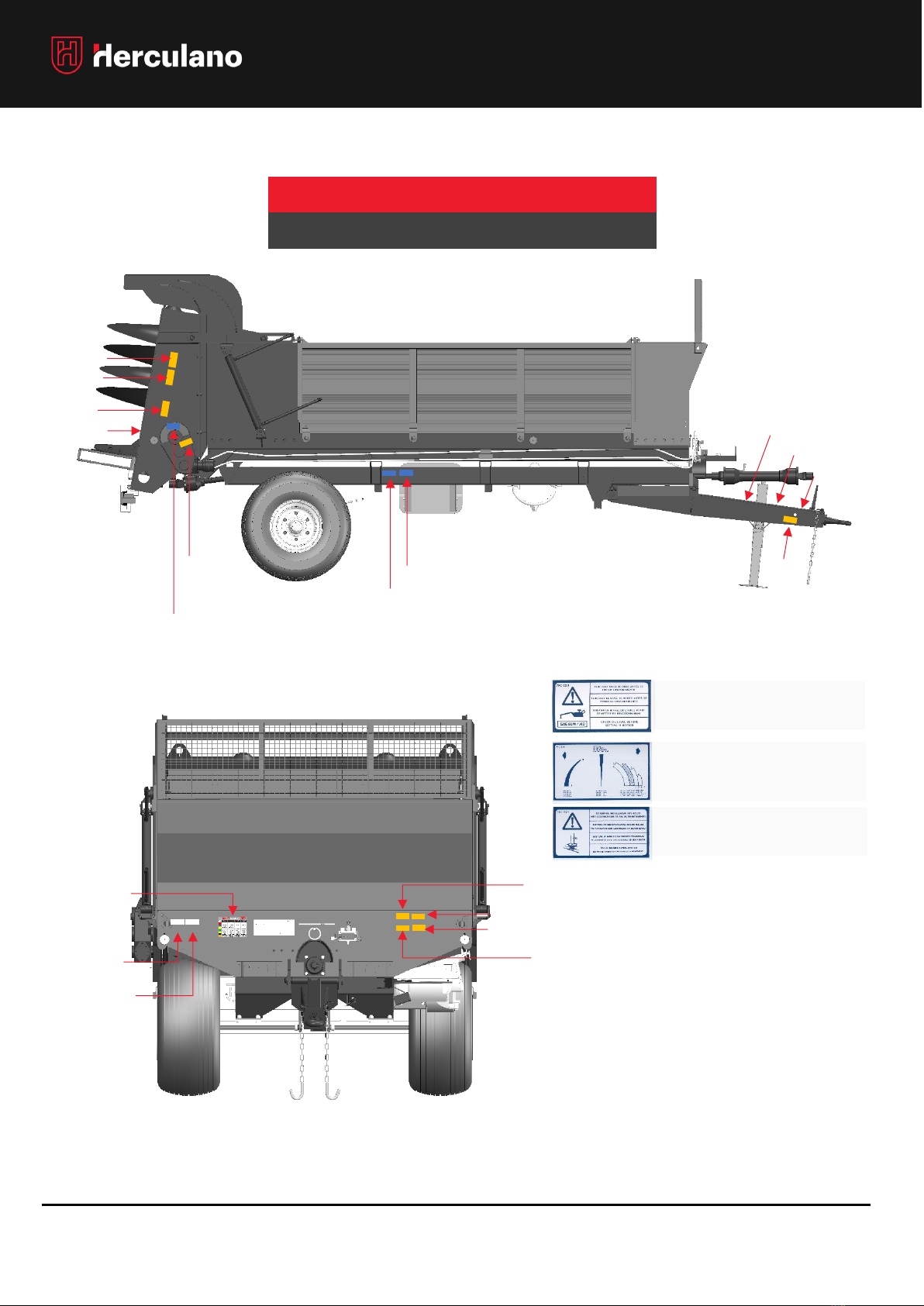
WARNING LABELS POSITION
7 AC 010
7 AC 014
7 AC 022 or
7 AC 104
7 AC 007
7 AC 008
7 AC 004
7 AC 137.1
7 AC 137.2
7 AC 126.2
7 AC 111
7 AC 124
7 AC 124.1 or 7 AC 135
7 AC 132
7 AC 024
7 AC 118
7 AC 118.1
7 AC 001
7 AC 002
7 AC 124
7 AC 116
LUBRICATION
SYSTEM
7 AC 047
7 AC 082
Matching timetable of the hydraulic function
by colour.
(When applicable)
7 AC 128
H2RS | H2RS-RG (EXCEPT H2RS 6)
OPERATOR’S MANUAL: H2RS | H2RS –RG | H4R
12
SAFETY
WARNING LABELS POSITION
7 AC 004
7 AC 008
7 AC 022
7 AC 010
7 AC 014
7 AC 007
H2RS 6 | H4R
7 AC 082
7 AC 111
7 AC 082
7 AC 024
7 AC 026**
7 AC 023***
SISTEMA DE
LUBRIFICAÇÃO
7 AC 047
7 AC 128
7 AC 001
7 AC 002
7 AC 124*
7 AC 124.1*
*It varies according to the country of use.
** Only for mechanical moving floor.
*** Only for hydraulic moving floor.
Check the oil level before setting in
motion.
7 AC 023
Instruction for reversing lever.
7 AC 026
Rools immobilization syetem.
7 AC 027
7 AC 027**

OPERATOR’S MANUAL: H2RS | H2RS –RG | H4R
13
TECHNICAL SPECIFICATIONS
SPREADERS: H2RS
H2RS6
H2RS9
H2RS11 RG
H2RS12
H2RS14
H2RS18
H2RS18 RG
INDICATIVE EMPTY
WEIGHT (t)
2,8
3,8
4,4
4,93
5,27
6,61
8,16
CAPACITY(m3)
5,2
8,7
10,4
11,5
13,1
17,8
17,8
INTERIOR (mm)
3650x1930x700
4650x1800x1000
5550x1440x1320
4700x2150x1220
4700x2150x1420
5700x2360x1420
5700x2150x1420
TOTAL LEGHT (mm)
6500
7580
8200
7210
7210
8320
8530
TOTAL WIDTH (mm)
2300
2480
3000
2500
2500
2540
2500
TOTAL HEIGHT (mm)
1180
1290
1380
1380
1530
1580
1700
SUSPENSION TYPE
-
-
-
BOGGIE
BOGGIE
BOGGIE
BOGGIE
AXLE TYPE
(Series EQ.)
Fixo
Fixo
Fixo
2 FIXED AXLE
2 FIXED AXLE
2 FIXED AXLE
2 FIXED AXLE
AXLE SQUARE (mm)
80
100
110
100
100
100
150
NO. STUDS
6
10
10
8
8
10
10
HUBS
300 x 60
406 x 120
406 x 140
400 x 80
400 x 80
406 x 120
406 x 120
AXLE TRACK (mm)
1600
1750
2150
1750
1750
2000
1900
P.T.O. (R.P.M)
540
540
540
540
540
1000
1000
DIAMETER - BEATERS
(mm)
990
800
755
755
755
755
755
CARDAN
(Series EQ.)
Semi-
Homokinetic
Homokinetic
Homokinetic
Homokinetic
Homokinetic
Homokinetic
Homokinetic
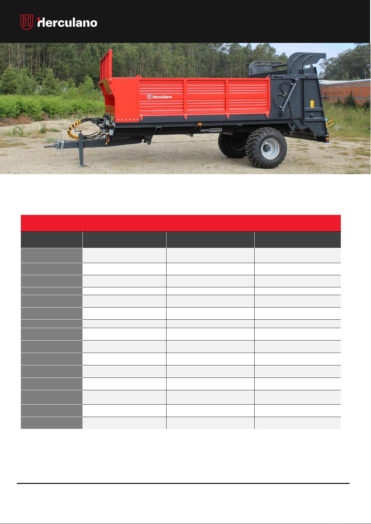
H2RS | H4R MAIN FEATURES
STEEL MONOCOQUE BODY
(H2RS9 OR ABOVE)
2 SPREADING BEATERS
(H2RS)
4 SPREADING BEATERS
(H4R)
REMOVABLE GROUP OF BEATERS
(SÉRIE H2RS9 OR ABOVE)
FIXED / FORCED STEERRING / SELF-STEERING AXLES
HYDRAULIC / PNEUMATIC BRAKING
LED LIGHTNING
(H2RS9 OR ABOVE | H4R, NOT APPLICABLE)
POWER TAKE OFF (PTO)
•The presented values refer to “STANDARD” models;
•Dimensions vary depending on the type of tires that the trailer is fitted with, taking into account their dimensions.
OPERATOR’S MANUAL: H2RS | H2RS –RG | H4R
14
TECHNICAL SPECIFICATIONS
SPREADERS: H4R
H4R4
H4R5
H4R6
INDICATIVE EMPTY WEIGHT
(t)
1.6
1.9
2.4
CAPACITY(m3)
4.2
5.2
6.0
INTERIOR (mm)
3180x1500x700
3420x1700x700
3680x1900x700
TOTAL LEGHT (mm)
5250
5500
5780
TOTAL WIDTH (mm)
1850
2050
2300
TOTAL HEIGHT (mm)
2370
2370
2300
SUSPENSION TYPE
-
-
-
AXLE TYPE
(Series EQ.)
Fixo
Fixo
Fixo
AXLE SQUARE (mm)
70
80
80
NO. STUDS
6
6
6
HUBS
300 x 60
300 x 60
300 x 60
AXLE TRACK (mm)
1400
1500
1600
P.T.O. (R.P.M)
540
540
540
DIAMETER - BEATERS (mm)
390
390
390
CARDAN
(Series EQ.)
Semi-Homokinetic
Semi-Homokinetic
Semi-Homokinetic
•The presented values refer to “STANDARD” models;
•Dimensions vary depending on the type of tires that the trailer is fitted with, taking into account their
dimensions.
•

OPERATOR’S MANUAL: H2RS | H2RS –RG | H4R
15
TRANSMISSION CARDAN
HOMOKINETIC
GENERAL AND SAFETY RULES
NOTE: Carefully read the Transmission
Cardan Instruction Manual!
The following recommendations do not in any way replace those
existing in the Cardan Manual. Consult it and respect all
instructions and safety recommendations contained therein.
SEMI-HOMOKINETIC
Homokinetic joint
Simple joint
If your cardan is SEMI-HOMOKINETIC (with only one homokinetic
joint on the tractor side), its shaft must be as close as possible to
the tractor's coupling shaft.
If your cardan is HOMOKINETIC (with two homokinetic joints), the
tractor hitch shaft must be (as much as possible) in the middle of
the space between the two joints.
•In the transmission simple joint (tank side), it is
recommended to work with angles that do not
exceed 16º at 540r.p.m. and the 9th to 1000r.p.m.
(See cardan manual).
•The homokinetic joint allows a maximum working
and rest angle of 70º.
•Always respect the cardan safety regulations and
existing warning labels. Keep them in good condition
or replace them if necessary.
Danger of dragging!
Power take-off transmission shaft connected to a machine!
7 AC 008
•Never remove the cardan's plastic protections!
•Attach safety chains at suitable points on the tractor and in
the tank!
•ATENTION! Before starting work, make sure that there are
no loose safety guards and parts or tools on the cardan
axle!
•Never step on or climb onto the
cardan at any time!
•Never use the cardan with damaged
safety guards
•Before starting work, check the length of the
Transmission cardan in the transport position and in the
working position. Make sure that the cardan assembly
respects its safety parameters. (See cardanl manual)
•If the cardan is excessively long or short, it can cause
damage, both in the tractor and in the cistern. This type
of damage is not covered under the warranty.
Serious fatal errors can occur if the proper precautions
are not taken and if the safety measures are not
respected.

OPERATOR’S MANUAL: H2RS | H2RS –RG | H4R
16
TRAILER COUPLING TO THE TRACTOR
ACOPLAMENTO INICIAL AO TRATOR
When you need to couple / uncouple the trailer to
the tractor, no one should be present in the area
between the two vehicles! This is considered a
danger zone!
NOTE: Before starting the coupling, make sure that the
trailer is on a level ground and that the parking brake
is properly on. If you have chocks, always make sure
that the trailer wheels are chocked before starting
the following procedures.
TRAILER COUPLING TO TRATOR
1º Align and move the tractor’s coupler towards the
coupler's device of the trailer’s drawbar.
2º Connect the drawbar’s safety chains to the
tractor;
3º Connect all trailer's hydraulic and pneumatic
hoses (if applicable) to the tractor's hydraulic
sockets;
Note: The tractor must be off;
4º Connect the plugs of the trailer electrical systems
to the tractor’s socket;
5º Operate the drawbar’s rest hydraulic cylinder in
order to level the coupling device with the
tractor’s coupler;
6º
! WARNING !
6º Slowly move the tractor in reverse until it aligns
the tractor's coupler with the coupler's device
of the trailer’s drawbar. When they are properly
aligned, proceed to the coupling.
7º Make sure you have completed the previous
step correctly and retract the hydraulic cylinder
from the drawbar to the operating position;
8º Remove the chocks from the wheels (if fitted)
and proceed to work safely by releasing the
hand brake / parking brake.
PEOPLE IN THE DANGER ZONE BETWEEN THE
TRACTOR AND THE TRAILER MAY BE CRUSHED OR
RUN OVER!
KEPP OUT ALL PEOPLE FROM THE DANGER ZONE WHEN TO
COUPLING / UNCOUPLING THE TRAILER;
NO ONE IS AUTHORIZED TO RAMAIN ALONGSIDE THE
TRAILER AXELS / TRATOR WHEN THEY ARE BEING COUPLED;
THE OPERATOR MUST ALLWAYAS KEEP WELL AWAY FROM
FRO THE VEHICLE WEELS.

OPERATOR’S MANUAL: H2RS | H2RS –RG | H4R
17
HYDRAULIC SYSTEMS
CONNECTION OF HYDRAULIC SYSTEMS
NOTE: For safety reasons, never connect or
disconnect the hydraulic systems while the box is
tipped! When connecting or disconnecting the
hydraulic systems, make sure that the edges of the
quick-connect valves are not dirty!
The connections of the tractor’s hydraulic functions
must not exceed 180 bar. Pressures above this value
may damage the systems.
HYDRAULIC SYSTEMS
•DRAWBAR REST
•HYDRAULIC BRAKING SYSTEM - (OPTIONAL)
•SELF STEERING AXLE - (OPTIONAL)
•FORCED STEERING AXLE - (OPTIONAL)
•HYDRAULIC REAR - (OPTIONAL)
•ESTEIRA HIDRÁULICA
1st. Move the tractor closer and lower the tractor’s
linkage in order to have access to the hydraulic
sockets area;
2nd. Turn off the tractor engine;
3rd. With the trailer properly immobilized and with
chocks on the wheels, connect the hydraulic
hoses of all systems to the corresponding
hydraulic sockets on the tractor. Follow all
Hydraulic Systems connection procedures on the
following pages;
4th.Connect the electrical plug of the Lightning
System and the function control to the tractor,
5th.Switch on the tractor's engine and reposition the
linkage in an elevated position to prevent collision
with the drawbar during transport.
6th.Test systems one by one and safely. If all work
properly, you can start work.
DRAWBAR REST
T
P
1. Properly put the tractor’s brake on and then
switch it off;
2. Close the safety tap on one of the hydraulic
hoses on the drawbar;
3. Connect the two appropriate hoses to the
tractor;
If you experience difficulties connecting the hose
that contains the stopcock, first make sure that it
is closed and try to activate the quick attachment
valve, in order to depressurize the short link
present between the two elements. In doing so, it
should be easy to make the coupling.
4. After connecting the hoses to the tractor, open
the safety stopcock.
5. Before reconnecting the tractor, make sure to
complete the connection of all the other systems.
NOTE: Never disconnect the hoses from the tractor without
first closing the safety stopcock.
NOTE: The Forced Steering axle system works independently,
requiring no hydraulic connection to the tractor.

OPERATOR’S MANUAL: H2RS | H2RS –RG | H4R
18
HYDRAULIC SYSTEMS
The discharge line of this valve must be connected to a tractor
line connected to the oil tank of the trailer's braking system. This
line can be the floating line, if it exists and if it matches the
requirement mentioned above. When in doubt, check the
tractor's manual or ask the manufacturer for support.
NOTE: A poor connection can damage the tractor!
HYDRAULIC BRAKING SYSTEM
WITH 3-POSITION VALVE (WHEN APPLICABLE)
This hydraulic braking system is equipped with a 3-
position valve that allows the intensity of the braking
forces to be adjusted according to the load it carries
Therefore, before driving with the trailer empty, half
full or completely full, you can adjust the valve to the
corresponding position in order to adjust the braking
forces to the load you are carrying.
The connection of this system is guaranteed using two
hydraulic hoses that must be connected to the brake
valve and a line with connection to the oil tank of the
tractor's braking system.
Make sure that you connect this system correctly
each time you proceed to the trailer's coupling.
Always respect speed limits to not jeopardize your
safety and the safety of others.
1º Carefully bring the tractor to the tow boom in
order to engage, lock the tractor an turn of the
engine;
2º Connect the hydraulic hoses of the braking
systems ti the respective lines of the tractor;
When connecting, make sure that the quick
connection valves are free from dirt.
3º Start the tractor engine and teste the braking
system and check if the system works correctly.
NOTE: The braking system must be connected to the tractor on
the appropriate lines and it must not exceed 115 bar.
NOTE: Do not drive on
public roads if the
braking system is not
working properly or if
you detect any
anomaly that could
jeopardize the safety
of the vehicle or
people's safety!
BRAKING VALVE –3 POSITIONS
MIN = EMPTY
MÉD = ½ LOAD
MAX. = FULL (MAX PRESURE = 115 bar)
! WARNING!
!
CONNECT THE HYDRAULIC
HOSES TO THE TRACTOR
ADJUST BRAKINGPRESSURE
ON THE 3-POSITION VALVE!
MIN. / MED. / MAX
BRAKE’S
HYDRAULIC
CYLINDER

OPERATOR’S MANUAL: H2RS | H2RS –RG | H4R
19
HYDRAULIC SYSTEMS
HYDRAULIC BRAKING SYSTEM
(WHEN APPLICABLE)
The simple hydraulic braking system is installed, which
must be connected to the tractor, through the hose
that contains the ½ female quick valve, as shown in
the following diagram:
If you notice overheating in the brake drums, or if you
feel that braking is insufficient, you may need to adjust
the brake, especially after the first few runs.
For that, and only if your equipment is equipped with
adjustable handles, proceed to tighten / loosen the
adjustment screw in them (BIELLETTES) in order to
obtain the necessary looseness between the jaws and
the drum.
ADJUSTING
SCREW
CLOCKWISE
=
INCREASE TENSION
ANTICLOCKWISE
=
DECREASE TENSION
Long use of the equipment is likely to cause
considerable wear on the pads. In this
case, check if it is necessary to replace
them or if the tightening of the adjustment
screw on the handles is sufficient to
guarantee the braking effect. Check
"Brake / Jaw Adjustment".
do Travão/Maxilas” no capítulo
Manutenção.
BIELLETTE
CONNECT THE HYDRAULIC
HOSES TO THE TRACTOR
BRAKE’S
HYDRAULIC
CYLINDER

OPERATOR’S MANUAL: H2RS | H2RS –RG | H4R
20
HYDRAULIC SYSTEMS
HYDRAULIC BRAKING SYSTEM
3 POSITION CONTROL + ELECTRICALLY CONTROL VALVES
(WHEN APPLICABLE)
This system was specifically developed to assist the
user to easily adjust the braking pressure and without
leaving the tractor, according to the load it transports
on the trailer, from an electric control placed on the
tractor.
This way, with the help of the control, the driver can
change the braking pressures to:
0= EMPTY (35bar)
½= HALF LOAD (75bar)
1= FULL (115bar)
(MAX PRESSURE = 115 BAR)
VALVE BLOCK
(example)
NOTE: The valves and
control setting may
change depending on
supplier or product
changes.
TRAILER HYDRAULIC BRAKING
LINE
HYDRAULIC BRAKE LINE FROM
THE TRACTOR TO THE TRAILER
CONNECTION TO THE TRACTOR
12V-DC
0= EMPTY
½= HALF LOAD
1= FULL
(MAX PRESSURE = 115 BAR)
This manual suits for next models
2
Table of contents


