Ferrari Costruzioni Meccaniche FPC User manual


Ferrari Costruzioni Meccaniche Srl -- Strada Squadri 6, 46040 Guidizzolo (MN) Italy -- Phone +39 0376 819342
www.ferraricostruzioni.com
3
1. STARTING
At starting the touchscreen shows the logo “Ferrari Costruzioni Meccaniche” for approximately twenty
seconds, this time is necessary to load the operating system (Fig.0).
Fig. 0
A page with the logo Fastblock, the version of the loaded software on the device (ex: 3.1) and a loading
bar (Fig.1) will appear.
Fig. 1
A) Software version.
Once loaded, the system starts the connection via CAN BUS with the control unit FPC: in case of
communication problem with the control unit, the loading bar will constantly be shown, and when the
connection will be correctly set up, the system will start the resetting procedure, this means that the
planting units will be in the correct position to start working (Fig.2).
A

Ferrari Costruzioni Meccaniche Srl -- Strada Squadri 6, 46040 Guidizzolo (MN) Italy -- Phone +39 0376 819342
www.ferraricostruzioni.com
4
Fig. 2
2. WORK MENU
2.1 MAIN PAGE
Once the resetting procedure will be completed, the main work page will be shown (Fig.3).
Fig. 3
A) In this frame the work speed is shown in real time. The speed can be shown in “plants/hour”
or in “meter/hour” (“yards/hour” if the Anglo-Saxon metric system has been selected).
Alternativly it is possible to view the transplanted plants per hectare (since this data varies
when the distance set in the row changes).
B) Selection key of the data to be displayed on frame A).
C) Indication of the electric supply tension.
D) Access to the alarms control page.
E) Access to the regulation of the position where the plant is placed inside the hole made
through the muching film (timing).
F) Distance increase key.
A
B
A
C
D
E
F
G
H
I
J
Ferrari Costruzioni Meccaniche Srl -- Strada Squadri 6, 46040 Guidizzolo (MN) Italy -- Phone +39 0376 819342
www.ferraricostruzioni.com
5
G) Access to the work parameter page.
H) Distance decrease key.
I) Transplanting distance.
J) Access to the data archive page.
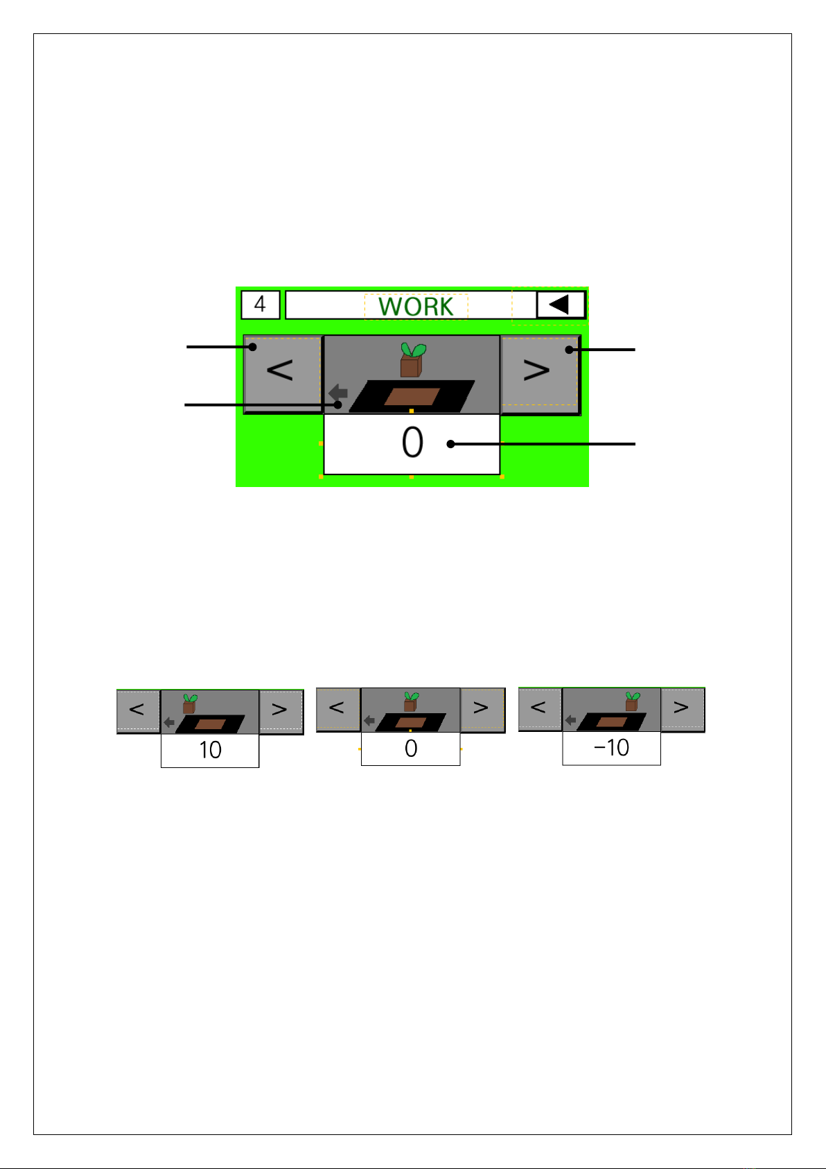
2.2 TIMING REGULATION
By pressing the key E-Fig3 it is possible to enter the timing regulation page.
Fig. 3
In this page it is possible to set the timing value, this means the position where the plant is
placed inside the hole made by the mulching film.
A) Shift back the laying point of the square block.
B) Timing value (range from -10 to +10).
C) The arrow indicates the work advancement way.
D) Shift forward the laying point of the square block.
Fig. 4
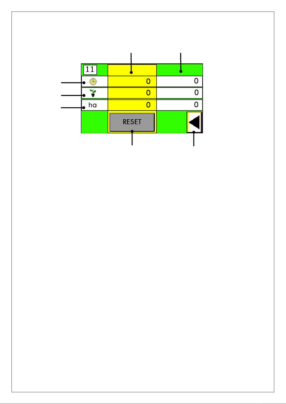
2.3 DATA ARCHIVE PAGE
By pressing the key J-Fig3 it is possible to enter the data archive page (Fig.5).
D
A
B
C
Ferrari Costruzioni Meccaniche Srl -- Strada Squadri 6, 46040 Guidizzolo (MN) Italy -- Phone +39 0376 819342
www.ferraricostruzioni.com
6
Fig. 5
A) Partial data column
B) Total data column
C) Key to turn back to the main work page.
D) Key RESET of the partial data: press to zero the partial data
E) Work hectars (Acres if the Anglo-Saxon metric system has been selected)
F) Transplanted plants
G) Work hours
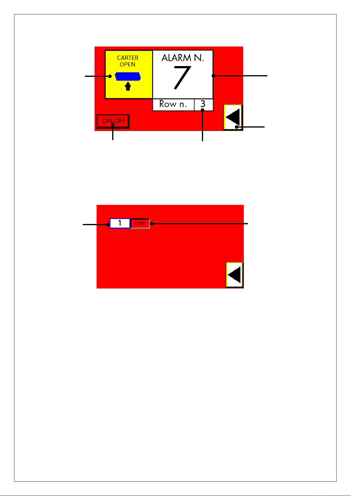
2.4 ALARMS SIGNAL
When an alarm comes up the icon background (D) of the work menu (Fig. 1) becomes red and
intermittent acoustic signal starts.
With reference to (Fig. 6):
A) Alarm number indication.
B) Go back to the main page of the work menu.
C) Indication of the element number (Row n.) which has an anomaly (this information comes out if
the alarm refers to a specific unit). In case of “multimaster” system, if the alarm refers to a specific
frame, the indication (Frame n.) will be shown and the frame number related to the alarm.
D) Access to the page of alarm starting/shut-off
E) Alarm reference icon.
For the alarms description please refer to the chapter “6. ALARMS”.
A
B
C
D
E
F
G
Ferrari Costruzioni Meccaniche Srl -- Strada Squadri 6, 46040 Guidizzolo (MN) Italy -- Phone +39 0376 819342
www.ferraricostruzioni.com
7
Fig. 6
Press the key D-Fig.6 to enter the alarms starting/shut-off page (Fig.7), where it is possible to disable
one or more than one alarms (except alarm n.3 that cannot be disabled because of safety reasons).
Fig. 7
A) Alarm number.
B) Alarm Rating/Disablement.
A
B
C
D
E
A
B
Ferrari Costruzioni Meccaniche Srl -- Strada Squadri 6, 46040 Guidizzolo (MN) Italy -- Phone +39 0376 819342
www.ferraricostruzioni.com
8
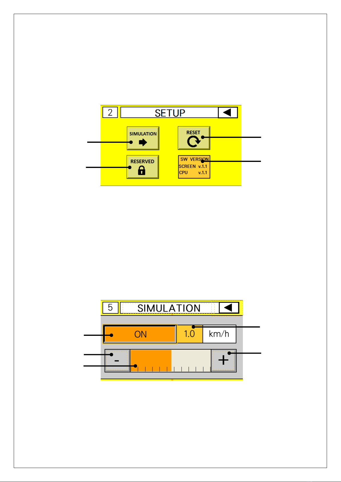
3. PROGRAM MENU
3.1 MAIN PAGE
Press the key G-Fig3 to enter the program menu (Fig.8).
Fig. 8
A) Reset key: by pressing the key reset an impulse is given to the transplanting units, so that they
move to the correct position to start working.
B) Software version: Screen (touchscreen OPUS A3) and CPU (control unit).
C) Access key to the reserved menu.
D) Access to the simulation page (vedi 3.2).
3.2 SIMULATION PAGE
Press the key E-Fig7 to enter the simulation page (Fig.9).
Fig. 9
A
B
D
C
A
B
D
E
C

Ferrari Costruzioni Meccaniche Srl -- Strada Squadri 6, 46040 Guidizzolo (MN) Italy -- Phone +39 0376 819342
www.ferraricostruzioni.com
9
A) Simulation speed set.
B) Speed increase key.
C) Speed decrease key.
D) Speed Bar graph.
E) Selector Start/Shut-off Simulation
In the simulation page it is possible to simulate the machine advancement and so to activate the
transplanting units movement. By means of the selector E) it is possible to activate or to deactivate
the simulation, and by means of the keys B) and C) it is possible to increase or to decrease the
simulated speed.
It is possible to set a distance in km/h (from 0 to 2 km/h) and the transplanting elements will move
as fast as to ensure the distance set in the main menu.
4. RESERVED SETUP MENU
Press the key A-Fig7 and enter the password to ask to Ferrari Costruzioni Meccaniche to enter the
reserved program menu. It is important not to modify the parameters contained in this section without
the supervision of a technician of Ferrari Costruzioni Meccaniche.
4.1 RESERVED SETUP 1
Fig. 10
A) ROWS: number of machine transplanting elements.
B) TRACK WIDTH: machine working width (in centimetres).
C) ENCODER WHEEL [imp/m]: number of pulses per metre of the encoder that measures the
machine travel speed.
D) UNIT OF MEASURE [cm/inches]: selection of unit of measure to be used. By selecting “cm”
the measurements in the work menu will be expressed in centimetres and hectares; by
selecting “inches” the measurements in the work menu will be expressed in inches and acres.
A
B
C
D
Ferrari Costruzioni Meccaniche Srl -- Strada Squadri 6, 46040 Guidizzolo (MN) Italy -- Phone +39 0376 819342
www.ferraricostruzioni.com
10
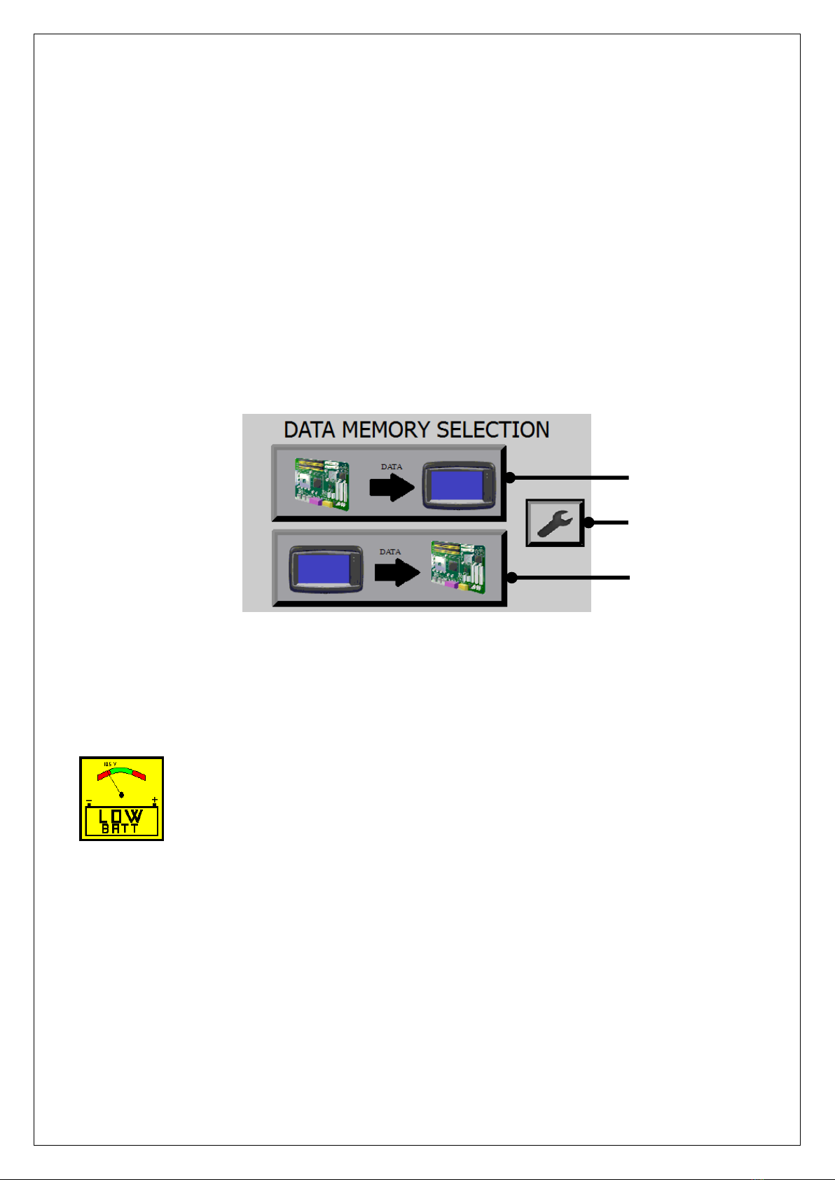
5. REPLACEMENT
TOUCHSCREEN/CENTRAL UNIT
In case of breakage, damage or bad functioning of the Touchscreen or of the motherboard (central unit)
the broken device must be immediately replaced. Once the damaged device has been removed, a copy
of the parameters is saved inside the functioning device. After the replacement, when the machine is
started, the page on fig. 22 is shown.
Press the key (C) to copy the memory of the Touchscreen on the new motherboard (CPU) installed, while
press the key (A) to copy the memory of the motherboard on the new Touchscreen installed. Press the
key (B) to enter a detailed list of the data saved on both devices.
Fig.11
6. ALARMS
ALARM N.1: INCORRECT ELECTRICAL SUPPLY
Make sure that the electrical connections are well fastened, especially that the battery clamps are not
oxidised and that the alternator work properly.
A
C
B

Ferrari Costruzioni Meccaniche Srl -- Strada Squadri 6, 46040 Guidizzolo (MN) Italy -- Phone +39 0376 819342
www.ferraricostruzioni.com
11
7.INDEX
1. STARTING ------------------------------------------------------------------------- 1
2. WORK MENU ------------------------------------------------------------ 2
2.1 MAIN PAGE --------------------------------------------------------------------- 3
2.2 TIMING REGULATION ------------------------------------------------------- 4
2.3 DATA ARCHIVE PAGE ---------------------------------------------------------- 5
2.4 ALARMS SIGNAL -------------------------------------------------------------- 6
3. PROGRAM MENU ------------------------------------------------------- 6
3.1 MAIN PAGE ---------------------------------------------------------------------- 6
3.2 SIMULATION PAGE -------------------------------------------------------------- 7
4. RESERVED SETUP MENU -------------------------------------------- 9
4.1 RESERVED SETUP 1 ------------------------------------------------------------- 9
5. REPLACEMENT TOUCHSCREEN / CENTRAL UNIT----------------- 10
6. ALARMS ------------------------------------------------------------------ 10
7. INDEX ---------------------------------------------------------------------

Other manuals for FPC
1
Table of contents
Popular Touchscreen manuals by other brands


Philips
Philips 95242A Installation & operation guide

Savant
Savant ITP-E5500V2x Quick reference guide

Elo TouchSystems
Elo TouchSystems 1938L user guide

Elo TouchSystems
Elo TouchSystems 2420L Product dimensions

Cooper
Cooper iLumin Plus TSE55-B installation instructions

Advantech
Advantech TPC-660E user manual


