Ferroflex Aluminum Rolling Up High Speed Door User manual

Instruction manual
Aluminum rolling-up door
ALUMINUM ROLLING-UP DOOR
MOT-A14
Rev.1

DECLARATION OF PERFORMANCE
Model: Aluminum Rolling Up High Speed Door
For the use as Industrial High Speed door for pedestrian and vehicle traffic.
Evaluation and Verification System of constancy of performance.
System 3. According with European Standards 13241-1:2003
Notified body: Cidemco nº1239
Document issued and date: Certificate 12707 del 09/03/2006
Performance declared.
Water tightness
Not Proceeding
Emissions of hazardous substances
Qualify
Air Behaviour
Class 2
Thermal resistance
Not Proceeding
Air permeability
Not Proceeding
Safe Opening
Qualify
Mechanical resistance
Qualify
Setting force
Qualify
Durability
100,000 cycles
For the present, the manufacturer, declares, under his responsibility, that the rapid door
does not contain dangerous products included in the list published by the European Union
and therefore it is in accordance with the essential safety requirements of the following
Directives:
•Construction Products Regulation (EU) 305/2011, laying down harmonized conditions for
the marketing of construction products.
•European Directive 06/42/CE, on the approximation of laws of Member States relating
Machinerys.
•European Directive 06/95/CE, on the approximation of laws of Member States relating
electrical equipment designed for use within certain voltage limits.
•European Directive 04/108/CE, on the approximation of laws of the Member States
relating to electromagnetic compatibility.
2

For the specific requirement of this equipment, the following harmonized standard have
been applied:
•UNE-EN 13241-1:2004 + A1:2011. Industrial, commercial and garage door and gates. Part
1: Products without fire resistance or smoke control characteristics.
•UNE-EN 12453:2000. Industrial, commercials, and garage doors and gates. Safety in use
of power operated doors. Requirements.
•UNE-EN 12604:2000. Industrial, commercial and garage doors and gates. Mechanical
aspects. Requirements.
•UNE-EN 12424:2000. Industrial, commercial and garage doors and gates. Resistance to
wind load. Classification.
•UNE-EN 12635:2000. Industrial, commercial and garage doors and gates. Installation and use.
•UNE-EN 1037:1996 + A1:2008. Safety of machinery. Prevention of unexpected star-up.
•UNE-EN 60204-1:2007 + A1:2009. Safety of machinery. Electrical Equipment of Machines.
Part 1. General Requirements.
•UNE-EN 61000-6-2: 2006. Electromagnetic compatibility (EMC). Part 6. Generic standards.
Section 2. Inmunity for industrial environments.
•UNE-EN 61000-6-3:2007. Electromagnetic compatibility (EMC). Part 6.Generic standards.
Section 3.Emission standard for residential, commercial and light-industrial environments.
The described products are exclusively destined for the assembly with a control box
corresponding to the class 2 according to DIN 954 standard. The starting remains prohibited if the
whole installation, including the assembly, has not been validated in terms of conformity
regarding the applicable dispositions mentioned on above European Directives.
The declaration will be automatically cancelled if any modification is done on the installation
by user or any other part.
3

IDENTIFICATION CARD
4

Table of contents
1. Product’s description ............. PAG. 6
1.1. Door’s operating mode and Frame
1.1.1. Principle
1.1.2. Electrical Control box
1.2. Electrical security Devices
1.3. Motor
1.4. Technical Characteristics
1.5. Principle drawing
1.6. Fixing map
1.7.Inspection rules
2. Security information ............. PAG. 11
2.1. Application area and suitable use
2.2. User’s obligations
2.3. Explanation of used security symbols
2.4. General security information
3. Storage and handling ............. PAG. 13
3.1. Storage
3.2. Dimensions and weight
3.2.1. Dimensions of the palette with the door
3.2.2. Dimensions of the door, once installed
3.2.3. Weight of the door
3.3. Handling
3.4. Handing on the installation place
3.5. Gravity centre
4. To assemble and to dismantle ............. PAG. 14
4.1. Inspection of the delivery
4.2. Preparation of the installation
4.3. Door assembly
4.4. Control box assembly
4.5. Test and reception
4.6. Adjustment and starting
4.7.To dismantle
4.8. End of assembly
5. Breakdown ............. PAG. 29
5.1. Mechanics failures
5.2. Electrical failures
5.3. Manual operation in case of power failure
6. Maintenance ............. PAG. 31
6.1. After-Sale service
6.2. Control and maintenance
6.3. Cleaning
6.3.1. Cleaning and maintenance of the protector blade
6.3.2. Cleaning and maintenance of the door frame
6.3.3. Cleaning of surrounding areas
5

1. Description of the product
· 1.1. Door’s operating mode and Frame
The Aluminium rolling-up door is a vertical high-speed door with a top-mounted mechanism.
Lateral frames are used to drive the flexible blade. This blade is vertically opened and rolled up
on the superior part. The rolling axis roll-up the door thanks to the motoreductor.
For the closure, the blade goes down thanks to the weight on the inferior part,
guarantying the air-tightness.
· 1.1.1. Description
The door is composed by two lateral frames, a PVC blade as well as a rolling axis.
The door goes up and down thanks to the traction done by a motor allowing the movement.
The power of this last is done on an axis allowing to instantaneously vary the operating way.
On the inferior part of the blade there is a contactor safety allowing to invert its way as soon
as the minimum chock is detected; therefore to open the door by security. More over, on
the inferior part of the door, there is a security photocell to open the door if there is any
obstacle.
· 1.1.2. Electrical Control Box
The electrical control box is our Ref. MATRIX 6. This control box has been designed to be
used with motors supplied by the manufacturer which included mechanical limit switch. Its
corresponding instruction manual is supplied together with this assembly and Instruction
manual. Homologated according to UNE EN 12453 rule.
· Technical Data
For all MATRIX 6 boards.
For motor up to 3,0 KW.
Supply voltage: 3x230V/PE;
3x400V/PE. Control Voltage: 24 VDC.
Dimensions: 220 x 305 x 140 mm. IP56.
For bad weather or continuous water spray uses, we recommend the additional protector
cover.
Electronic board protected by a cover.
Pattern and fixing elements supplied.
Box with integrated push buttons (OPEN-CLOSE-EMERGENCY STOP-VOLTAGE LUMINOUS
INDICATOR).
Entry with corrugated pipe coupling elements.
6

· Functions
Operating mode selection: Present man or Automatic. Automatic
recognizing and evaluation for safety edge’s status.
Adjustable waiting time up to 90 sec. The door will be closed once the programmed time
finished.
Input for pull cord or remote control.
Input for intermittent indicator light or Traffic Light
. Slot for magnetic detector included.
Connection time adjustment for the motor break.
Input for the 3º micro switch of the limit switch.
Input for operating through frequency
inverter. LEDS status information.
Enclosure with Motor Circuit Protector, inversor and motherboard.
The operating door is impossible without original traction motor and
electrical control box.
· 1.2. Electrical security device
Before each descent movement, an internal test is done on the photocell and the electrical
control box (security category Nº2 according to the DIN EN-954-1 rule). In case of technical failure,
and for security reasons, the door will be automatically rolled up. If the contact of the safety edge
is damaged, the door will be also automatically rolled up for security reasons.
Photocell and safety edge must to be controlled per authorised staff each year.
· 1.3. Motor
The Folding up door is electrically activated through a motoreductor allowing the door to
operate is placed on the superior part of this one, being indistinctly installed on the right or
the left side according to the installation requirements. If there is no enough space for the
installation of the motoreductor, it is always possible to place it in frontal position with a
chain. The electrical control box includes a motor protector allowing to disconnect the
motor’s supply in case of over temperature of this one.
7
· 1.4. Technical Characteristics
Principle
High Speed Rolling-up Door
Opening way
Vertical
Application
Door for Exterior and Interior installations
Dimensions*
Maximum width: 4000mm / Maximum height: 4000mm
*It is possible to manufacture other dimensions under request
Opening Speed
0.9 m/s
Closure Speed
0.9 m/s
Assembly
Position interior and exterior
Motor
Electrical
Power supply
230/400v Three phases without Neutral
Motor Power
0,75 CV (According to door’s dimensions)
Electrical control box
MATRIX 6
Motor protection level
Motor Circuit Protector to 4A
Lateral frames
Aluminium
Blade
Polyester PVC with a thickness of 900g/m2,
and M2 Class for fire resistance
Dimensions
See herewith drawing
Frame fixing
See herewith fixing drawing
The manufacturer can feel free to technically modify the door, if these modifications
don’t break the Obligatory European Rule EN 13241-1:2003
8
·
·
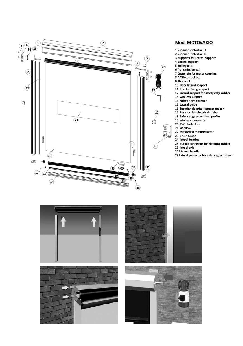
1.5. Principle drawing
1.6. Fixing map
9

· 1.7. Inspection Rules
Examination
Aluminium
rolling-up
METALLIC FRAME:
Assembly fixing
To tighten screws.
Once per year
To verify the soldering cord.
Once per year
Motoreductor
To verify the state and the wear of the break, as well as the correct
Once per year
operating mode of the break lever.
To verify the fixings motor screws.
Once per year
Rolling axis
To tighten fixings and bearings.
Once per year
Door blade
To verify the absence of fissures and stripes on the whole blade.
Once per year
To control blade fixings on the rolling axis as well as reinforcement bars.
Once per year
To control the electrical safety edge operating mode.
Once per year
Safety Edge
To verify the WIFI system.
Once per year
To verify the blade fixing, and the state of guides, cables spout and friction
pieces. Substitute all deformed friction pieces.
Once per year
To verify the state of contacts connector, cables and the electrical safety edge.
Once per year
Lateral frames
To verify the fixing and the vertical guides state.
Once per year
To control the cable way as well as the chain charged to conduct the energy.
Once per year
To verify the assembly and the operating mode of the photocell.
Once per year
To clean the photoelectrical barrier and the beam.
Once per year
Electrical control box and Added optional boards
To verify the entirety of the wiring map.
Once per year
To control the main switch and the closure of the control box.
Once per year
To verify the fixing.
Once per year
ELECTRICAL FUNCTIONS:
Run of the door
To control the opening and closure positions of the closure guides.
Once per year
To verify the fixing and the operating mode of the end of run switches.
Once per year
Security mechanisms and drive
To clean the optical of the security photoelectrical barrier.
Once per year
To verify the fixing and the operating mode of the end of run switches.
Once per year
Electrical components
To visually control and look for any kind of mechanical damage.
Once per year
Mechanical Functions
To verify the operating mode and the state of the couple support during the
Once per year
operating.
To examine the behaviour of the blade roll up.
Once per year
10

2. SECURITY INFORMATION
· 2.1. Application area and suitable use
If this data hasn’t be expressly mentioned, our high-speed doors have been designed and
tested to be used in normal conditions. For a use in particular conditions (excessive
temperature on a single side, over/under pressure or specific environment influences, etc…)
you have to select the more suitable and adapted option required by the situation. We will
be pleased to advice you, if you need it.
· 2.2. User’s obligations
The high-speed door has been designed ad manufactured according to a risks analyse and
to rigorous selection of rules to respect, as well as other technical specifications. Then, this
door corresponds to the updated state of the technique and guarantees an optimal security.
Nevertheless, this security level can only be obtained in the professional practice if you have
taken all required and necessary measures to this effect. Therefore, we strongly suggest you
to read these service instructions and to keep them:
The user has to specially check that:
·The installation, the starting, the inspection, the maintaining, the repair, the dismantle;
have to be only done by staff authorised by the manufacturer or by competent staff.
·Only authorised and enough experimented staff activate the high-speed door.
·The door must be only used according to expected application (see previously).
·The door must only be used if it is in perfect state, and mainly that security mechanisms
must be frequently controlled.
·These service instructions are always available close to the door’s installation, readable
and completes.
·The personal must be frequently prepared to all important matters concerning the door
and its correct use.
·All security information and warning notices marked on the machine are always available
and readable.
·Door maintenance must be done by qualified and authorised personal.
· 2.3. Explanation of used security symbols
These service instructions include following security symbols. The aim of these symbols is
to mainly attract the reader attention regarding the placed security texts:
They indicate risks of death, to damage machines, against health, or properties or environment.
11

Attention: danger for people or door’s installation.
Attention: Electrical voltage.
This symbol is used for information allowing a better understanding regarding
the door-operating mode.
Important Information
Information directly marked on the door and on the electrical control box have to
obligatory and entirely be observed and kept readable.
·2.4. General security information
·Please read carefully these service instructions and keep them.
·Security prescriptions described on these service instructions have to be respected.
·Do not use this door for unexpected applications. In the case of cession of this door to a
third person, these service instructions have to obligatory be transmitted.
·In case of damage of the electrical system activation, the door blade can be unlocked and
folded up unblocking the motor. Then, you have to use the crank supplied for this purpose.
·During the door’s operating, don’t touch lateral parts.
·The door operating area has to be free of people. These doors are destined to staff
circulation.
·Don’t run across the door opening. Cross it upright and at a normal speed.
·Maintain clean the area close to the door operating. Otherwise, accidents can occur.
·Don’t climb up the high-speed door.
·Don’t matter the labour done on the door, the mains switch has to be in ”OFF” or “0”
position and protected against any involuntary reactivation of the voltage.
·The door has to immediately be in out of order in case of damage (mechanical or electrical).
·The door can only be used at the mentioned and authorised feed voltage.
·Use only accessories or complementary devices homologated and authorised by the
manufacturer.
·Do not use the door if there are wind gusts. The door must to be maintained opened.
It is very important to respect these mentioned general security information as well as
points added in other chapters.
12
3. Storage and Handling
· 3.1. Storage
The high-speed door partially assembled is supplied on handling palette ant it is packaged
into transparent protector film.
Do not store the door at building outside.
The wooden cage has to be placed on a flat basis. It doesn’t be removed before
the beginning of the assembly.
The wooden cage has to be protected against any kind of mechanical damages.
· 3.2. Dimensions and weight
· 3.2.1. Dimensions of the handling palette with the door
The packaging dimensions are usually 450mm (Width) x 450mm (Height) x longer measure
(vertical or horizontal) + 1000mm
· 3.2.2. Dimensions of the door, once installed
13

Weight of the door
Weight of the door with the palette (in Kg).
Dimensions
2x2
3x3
4x4
Weight
110
180
210
· 3.3. Handling
During the handling to the installation place, you have to respect public security indications.
Be careful and avoid that the door slide or balance.
The door has to be lifted up to avoid any lateral swing.
· 3.4. Handling on the installation place
The different components of the door can only be removed of wooden cage, once wooden
cage on the installation place.
· 3.5. Gravity centre
It is possible to interpose intermediaries values.
4. To assemble and to dismantle
· 4.1. Inspection of the delivery
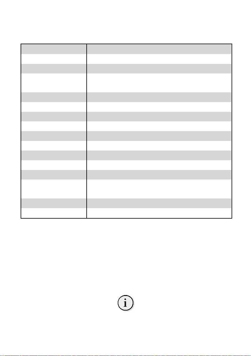
The door is preassembled at the delivery and it is composed by
3 components into the wooden cage:
·The first component is composed by 2 lateral guides
·The second component is Superior protection guide
including blade door with safety edge and Motoreductor.
·The third component is a box with fixing materials and
electrical components.
14
· 4.2. Preparation of the installation
You have to verify on the place that the measures are corrects and fixing points are
accessible. Superior plates, supporting the rolling axis, have to be fixed on a good reinforced
concrete or soldered on a steel support.
You can add more fixing plates if necessary, correctly shared on the total length.
You have to measure the opening dimensions (width and height) and to verify them with
the delivery documents.
The high-speed door has to be assembled by qualified and authorised staff following
assembly instructions manuals.
The area has to be securitised and the circulation has to be completely forbidden.
· 4.3. To assemble
Check there is no obstacle to install the frame and check the are where the door will be
installed is correctly levelled, otherwise you must suitably level it.
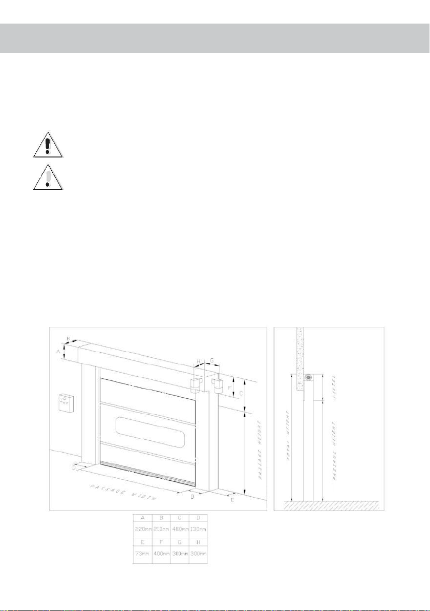
· 4.3.1. To start the assembly, you must
completely unpack lateral guides and superior
protection cover. You only have to remove the
packing corresponding to the necessary parts
(extremities) to fix lateral guides with superior
frame. The rest of packing must to be maintained
to avoid damaging the door during the assembly,
or the blade fall.
Place the upper roll-up drum on the floor and
insert the two lateral guides into the lateral plates
placed on the upper tray. Fix the different parts
using the 6 hexagonal Allen screws of size 8 x 10
and their corresponding washers.
· 4.3.2. Once lateral guides fixed, you
have to place the motoreductor on the door’s
axis, using the 2 screws of size 10 x 30 and their
corresponding washers.
15

· 4.3.3. Then, trough small carriage or lift-truck, you have to raise the assembly
inside the opening and support it on the wall. Level the door and fix the inferior part with
two screws on each guide as well as superior and lateral parts according to the wall. The
door is supplied with separate superior and lateral squares soldered on the door for its fixing.
We recommend you to fix the door on the wall using plastic plug or metallic plug for
concrete, or to solder it.
·4.3.4. Install the blade door into the
lateral guides. Roll-down the blade door to half
height to posteriorly check the motor rotation
way. Install the electrical control box in the guide
closest to the motoreductor at approximately
1300 or 1500 mm height from the ground, using
4,8 x 38mm screws and M6 plug and place cables
through supplied gutter for their correct
installation and protection.
We suggest you to install the control box close
to the door to activate the emergency stop if
necessary.
Install inferior photocells onto the inferior part
of the lateral guide at minimum 200 mm height from the floor and connect photocells,
following corresponding instructions manual.
·4.3.5. Fix the external push button using 4,8x38mm screw on the wished place.
We suggest you to place it close to the door in the opposite side regarding the control box.
external push button using M6 plugs and 4,8x38mm screws.
·4.3.6. To connect the electrical control box, you must carefully read and follow
the following instructions:
·Check the motor rotating and operating mode.
·Connect all security elements on the door.
·Adjust the maximum opening and closure door.
·Check the operating and programming modes as well as go down timing
16

· 4.4. Electrical Control Box
Matrix 6 control box
·4.4.1. Characteristics
·The MATRIX 6 Control box with 3 KW at 400V / 3~
as maximum with Mechanical limit Switch.
·Status indication through LEDs through a two digits
digital indicator:
·Mains voltage
-400V / 3~
-230V / 3~
-230V / 1~ (for single phase motors with frequency
inverter)
· Industrial door operating mode.
-Opening and closure by present man.
-Automatic opening and closure by present man (without safety edge protector).
-Automatic opening and closure (automatic closure combining with safety edge protector)
· Automatic detection and handling of three different safety edges types.
-8K2 Normally active contact.
· Automatic closure.
-After a waiting time (adjustable) from 1 up to 90 seconds as maximum.
-The time can be reduced interrupting the photocell light beam.
-it can be interrupted with auxiliary switch.
·Connection to supply external devices.
·Terminal block with indication to connect all necessary devices.
·Push button with 3 buttons on the cover OPENING / STOP / CLOSURE.
·Additional connections for control devices.
·4.4.2. First steps
-The control box is composed by a box with a
removing front cover.
-Open the front panel and insert cables through
inferior holes on the box.
17

· 4.4.3. Standard connections for power supply
The MATRIX 6 control box can be supplied according to the available voltage:
· 400V III + PE
You have to connect the 3 phases on L1, L2, L3
terminals and the ground cable to the corres-
ponding terminal. Check on the central part of
the motherboard that operating power supply
cables are in 400V and 0V terminals.
· 230V III + PE
You have to connect the 3 phases on L1, L2,
L3 terminals and the ground cable to the
corresponding terminal. Check on the
central part of themotherboard that
operating power supply cables are in 230V
and 0V terminals
Motor and break
To connect the motor to the motherboard, you
have to connect the 3 phases of the motor to U, V
and W terminals and the ground cable to the
corresponding terminal. Cables of the motor
break’s rectifier must to be connected to the
terminal indicated as “FRENO” on terminal block.
· 4.4.4. Inferior security photocell
Connect cables to the corresponding terminals according to the following drawing.
Transmitter Power supply through batteries
(included).
Receiver Terminal 1 -24V
Terminal 2 - GND
Terminal 3 - OUTPUT CONTACT
Terminal 4 - OUTPUT CONTACT
18
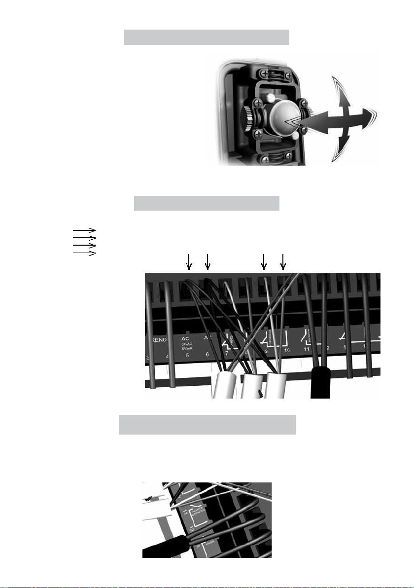
Inferior photocells adjustment
In order to correctly orientate photocells, you
have to use support for the fixing screw
available in the photocell support, vertically
leaning up to the light beam is reflected in the
mirror and sent back to the photocell. When
this happens, the 2 LED placed on photocell
electronic board will light on.
In order to verify that it operates correctly,
you have to pass the hand to cut the light
beam and the signal LED will be immediately
lighted and you could heard a small click from the contact change status.
CONNECTION ON CONTROL BOX
RED Cable
5(AC) Terminal
BLACK Cable
6(AC) Terminal
GREEN Cable
10(Photocell)
Terminal
YELLOWCable
9(Photocell) Terminal
GREEN
YELLOW
BLACK
RED
Additional external push button
Connection on 11 and 12 terminals. (Alternative push button)
19

· 4.4.5. Wireless-band
Wireless-band tramsitter: Connect the output rubber band electrical cable to terminals 1
and 2 on the Transmitter and activate the switch Nº1 to start the test.
Wireless-band receiver: Connect the receiver supply, terminals +0 and 12/24v to terminals
5 and 6. Connect terminals C and S from receiver to “Banda palpadora” terminals on the
control box.
TRANSMITTER
CONTROL BOX
RECEIVER
C and S from the receiver
To connect transmitter and receiver
1- Connect the receiver feed. (Be careful to respect the polarity when you use a DC power
supply) 2- Check transmitter and receiver options.
3- Match emitter and receiver following the programming
steps. 4- Install the transmitter on the door.
5- Wire the resistive safety edge to the transmitter and connect
it. 6- Install the receiver in the suitable place.
7- Wire the power supply, the test input and the receiver output to the control
box 8- Activate the power supply.
9- Make a test with the connected safety edge with door in different positions, mainly
close to the opening and closure position.
10- We recommend to follow step 1 to 4 before to install the device. Respect a minimum
distance of 1m between transmitter and receiver to have the optimal operating mode. 11-
Once assembled and matched transmitter and receiver , you have to maintain the
transmitter’s microswitch in position Nº1.
The transmitter and the receiver are supplied already
configured to operate in couple.
If the programming is not correct, you can reprogram them
proceeding as following:
A- All switches of transmitter and receiver must be to in down position (OFF), except the
Nº1 on transmitter.
B- Press the program button on the receiver and you will hear a “Beep” as validation. C-
Then, you will be in programming mode and the “program” LED will light to indicate it.
20
Table of contents
Popular Door manuals by other brands

Avalon
Avalon DVS Bungalow 95200135 installation guide

Marvel
Marvel 6SWCE-BB-G installation instructions

Johnson Hardware
Johnson Hardware 1700 instructions

B&D
B&D Roll-A-Door R1D installation instructions

Pella
Pella 818L0100 installation instructions

JR Home
JR Home RetractAway Installation instructions / warranty


