Cool-Air Doors CSA-5-BR Instruction manual

Cool-Air Doors
CSA-5-BR Bottom Rolling Slide Door
Assembly and Installation Instructions
1. Open all structural component and hardware boxes and compare with
itemized list in this instruction. Note: Structural components and hardware may
arrive in separate shipments.
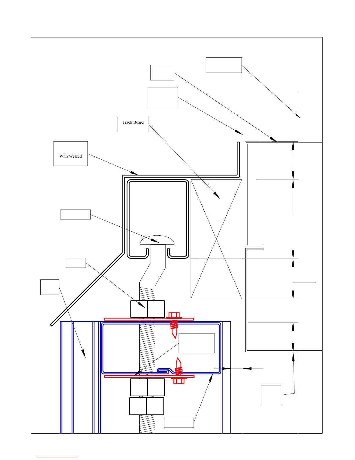
2. Install Top Guide track per print. Use mounting brackets spaced per print. The
16 gauge box track top guide must be drilled for a 3/8” bolt at each mount
bracket. Depending on the print for the job this will be either 24” or 48” on center.
3. Install 1-1/4” X 1-1/4” X 1/8” structural steel angle (supplied by others) bottom
guide per print. Use supplied mount clips with two TapCon screws per clip four
foot on center and at each joint. Recommended to tack weld bracket to bottom
guide in slotted hole. One TapCon per bracket authorized if tack welded except at
joints. Recommend cutting exposed end of bottom guide at 45 Degree angle to
reduce sharp cutting edge.
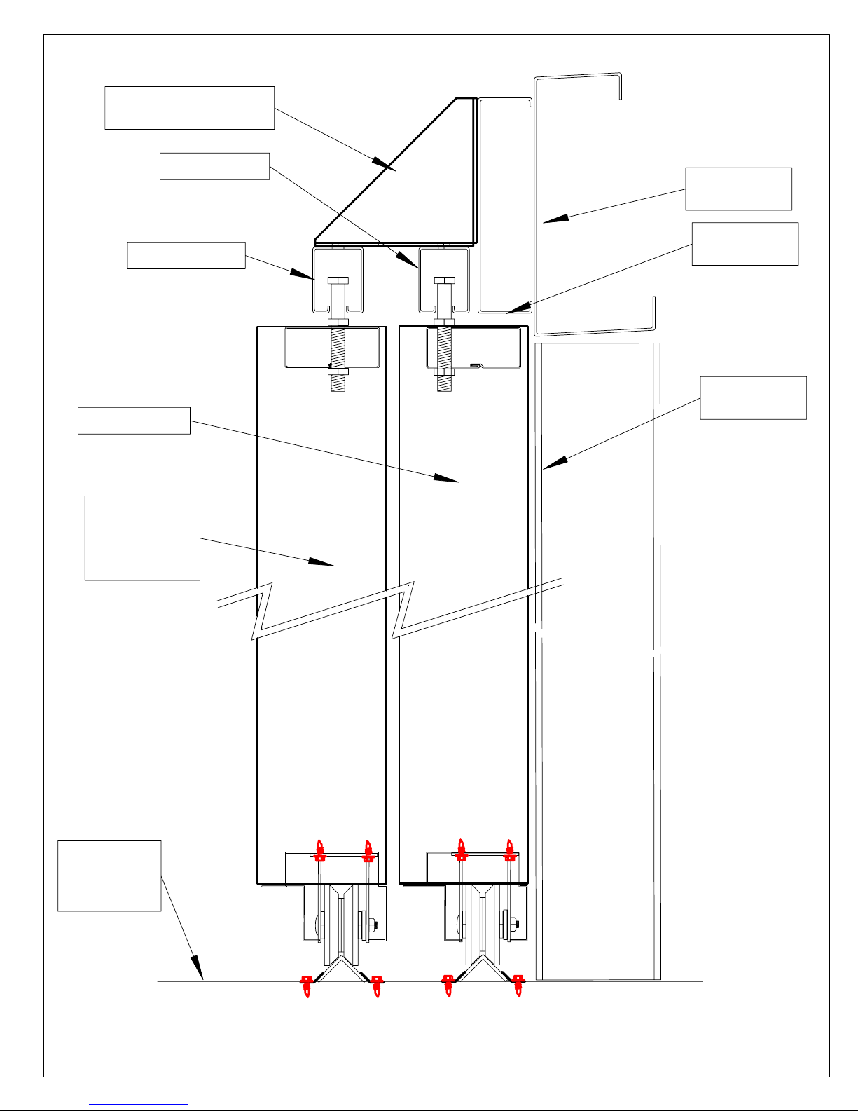
4. Measure distance between bottom of top track and top of bottom guide.
5. Allowing ¾” between top of door and bottom of top track and 3-1/2” for bottom
rail / bottom roller / bottom guide track, trim vertical to the measurement in step
4 minus 4-1/4”. Adjust if more or less space is needed between door and top track
or if different sized bottom guide is used.
6. Lay out Door structural components per component layout. Suggested to start
face down with protection to not scratch the paint.
7. Install Top Rail Girt and Aluminum Bottom Rail with one screw at each joint.
Check door print to determine quantity of top rail girts and determine if a bottom
rail reinforcing girt is supplied.
8. Locate and place remaining girts per the girt spacing. Numbers are starting
from top down. This may vary from the number specified if the verticals are
trimmed at site.
9. Internal reinforcements for the verticals are optional and may be supplied for
one or more vertical. If this vertical reinforcement girt section is supplied, install
the top girt for each panel, then install the reinforcing girt into the vertical, Tek
through the vertical near the top and near the bottom of the reinforcing member
and then butt the next horizontal girt tightly against the vertical reinforcing girt.
Continue this sequence all the way down. In some applications, a vertical
reinforcing girt will be supplied for only one side of the panel and not the other.
10. Square the door panel by measuring from corner to corner diagonally and
equalizing.
11. Lay out optional Walk Door Framed opening (if supplied) per print. Install tek
screws in girt installed as door jamb inside vertical only on rear side (away from
“J” trim)
12. Fasten two tek screws at each joint on the rear of door

13. Turn the door panel over and place one tek per joint.
14. Determine location of top guide pin on top rail. Drill ½” hole for guide pin. On
Doors with a single top rail girt a Trolley Support Bracket (2-3/8 X 4” drilled flat
plate) is supplied. This is installed on top and bottom at each hole drilled in top
rail using assembly tek screws. This is not required on doors with two or more top
rail girts.
15. Insert top guide pins in top rail. Secure with one nut on top and two under the
top rail. This pin can be rotated to adjust door to opening.
16. Insert bottom casters in bottom rail per drawings using assembly tek screws. If
Foot bolts are supplies see the installation notes for the location of the caster at
each foot bolt. Grease Zerk fitting is installed on the axle. This must face the rear
of the door as installed in the opening. Drill a 1” diameter access hole in the rear
flange of the bottom rail to service the Grease fitting.
17. Stand door up and slide door on bottom track and guide tip pin into top track
from each side of opening.
18. Install a Jamb latch at each side of opening.
19. Install a Center chain latch between panels on multiple panel systems
20. Foot Bolts are optionally supplied and are installed internally towards the center
of the opening. When supplied, the caster will have to be located far enough away
from the vertical to allow the foot bolt to move freely. Install the foot bolt to miss
the bottom guide. Drill a minimum ¾” hole 1” deep in the floor for the foot bolt.
Door maintenance:
1. Grease each caster with wheel bearing grease annually. More often in dust
areas and when the door is used frequently.
2. Check security of the top guide pins and tighten or replace if showing wear.
3. Check top guide track for wear and replace if needed. The top guide pin slides
in the top guide track and the track groove can be lubricated with grease if
desired.
4. Check the security of the bottom guide. Retighten or replace attachment
screws as necessary. Replace worn bottom guide rails as needed.
Manufactured and distributed under license by:
:R
CANNON BALL HNP

Cool-Air, Inc.
Front View - No Scale
Finished Floor
Supplied By Others
Not To Scale
Sheeting Height
Measured Door Height
Measured Opening Height
CSA-4.5-TH Four Panel
Girt Qty + Bottom Rail
Girt Spacing
1.00
Actual clear opening
Measured door width
Feet Inches Bottom Rolling Specifications & Dimensions for Print
50 0 Actual Clear Opening Width Panels 4
18 0 Actual Clear Opening Height
12 9 Outboard Panel Width
0 0 Center Panel Width - Three Panel Systems
12 9 Inboard Panel Width
12 9 Outrigger Width (structure by others) Both Sides on 2,4 and 6 Panel
50 6 Actual Finished Door Width
77 0 Outboard Guide 4 panel - Top Supplied / Bottom by Others
0 Outboard Guide 3 or 6 panel - Top Supplied / Bottom by Others
0 0 Center Guide 3 or 6 panel - Top Supplied / Bottom by Others
51 Inboard Guide - Top Supplied / Bottom by Others
75 6 Overall Width Clear Space required For Door Operation
50 0 Usable Width with door Open
1.5 Bottom Track Space Under Door Frame 1/18/2005
10 Space required for Top Track above bottom of Header - Side Mount Bracket
17 11.504 Measured Door Height - Door Lap Header 1"
17 9.504 Sheeting Height (Site Verify and Supplied By Others)
1 7.3 Girt Spacing (Top to Top of Girt) Girt Qty 11 Certified Components

Called Clear Opening Height
1.00
0.50
2.25
1.5
SpecifiedClearOpeningHeight
Header
(By Others)
Back to Back
8" "C" Shown
Measured Door Frame Height
2.00
Rear Surface
of Exterior
Building Sheeting
Cool-Air Bottom Rolling Two Panel Door Showing One Half Only
Sheetinglength
2.00
1.00
1.687
3.637 .25 to .50
3.75

Rear Plane of
Building Sheeting
Front plane of
Sheeting plus
at least 1/2"
Optional
Top Guide Track
White Cover
1-1/2" X 3-1/2"
Header
(by others)
1/2" Nut
Door
Vertical
Bottom
Of Clear
Opening
1.00
Top Guide Pin
0.68 in
1.18 in
2.32 in
1.12 in
Trolley support
Plate - One on top
one under girt
0.500
Top Door Girt

Building Structure
(by others)
Building Structure
(by others)
Building Structure
(by others)
Double Side Mount Bracket
(Available with cover Bracket)
Inboard Top Guide
Outboard Top Guide
Inboard Door Panel
Finished Floor
(Guide Rails May
be Recessed in
Concrete)
Outboard Door
Panel
(Alternating 2 Panel
or
4 Panel Doors)

1.00
1.50
Rear Of
Sheeting
Column
Truss
Door Panel
Double Track
Bracket
2.250
4.00
9.50 in
1.50
2.75
6.75
10.0
Inboard Door
Panel
3/8" Mounting
bolt, nut & washer
Adjustable
Top Guide
Pin
Support
Plate
Top and bottom
Top Rail
Pin Hole
Location
Site
Double Nut
or Lock Nut
Optional Cover
Bracket
Drill for 3/8" Bolt
for each bracket
16 Gauge
Square Track

2.00
5.50
Finished Floor
3/16 x 1-1/4"
TapCon
1/8" X 1.25"
Guide
(By Others)
Guide Bracket
48" on Center
& on Joints
Inside
Door
Outside
Door
12-14X3/4"
Tek
Screw
CSA-5-BR
07/17/2003 D. Coolman
Bottom Guide
Cool-Air, Inc.
Exterior Plane
Of Building
Sheeting and
Trim
1.00
0.50
2.00
Minimum 0.250
Minimum 0.250

CannonBall
#394
Aluminum
Bottom Rail
3" X 1-1/2"
Steel V-Groove
Wheel Angle Guide
Mount Bracket
Spaced 48" OC
& at all Joints
V-Groove
Wheel
Mounting
Bracket
Bottom Rolling Bottom Rail and Guide System
1.25 X 1.25 X
1/8" Steel Angle
Guide (Supplie
By Others) TapCon
Screw
2 Per Bracket
Assembly
10-14 X 5/8
Tek Screw
Four Places
Grease
Zert
Site Drill 1" hole
For Grease Zert
Access at
Each Caster
Floor

#394 Bottom
Rail
3" V-Groove
Caster
Place right at
Aluminum Vertical
12-14 Tek
CSA-4.5 Door
Vertical
#391 or #396
Site Drill 1" diameter
Hole INSIDE Flange
of Bottom Rail for
Grease Zert Access
Caster Location for CSA-4.5_BR Bottom Rolling Slider
Place Caster close to Vertical
Do Not move Caster towards
Door Center. Only move Caster
At Vertical with Foot Bolt installed.

Inboard Top Track Guide
Not Included for Center Panels
20 gauge Steel girt
Vertical Reinforcement
Between Each Horizontal Girt
All Verticals
OutBoard Top Track Guide - Full Width
Bottom Guide Angle
1.25 x 1.25 x .125 Steel
(by Others)
Girt Spacing
Space Girts using Vertical
Reinforcing Girt between
Horizontal Girts.
Dimension for
reference only.
20 Gauge
1.5" x 3.5"
Steel Tube
Girt per Panel
(see Size Print)
Vertical
Combo 119350 Double
Track bracket
Two Foot On Center
Guide Brackets
48" OC and
at Joints Tapcon
Two places
Center H Astragil
(not shown)
TEK Assembly
Screw Location
0ne Front - Two Rear
Each Joint
Vertical
Reinforcement
All verticals
Weather Strip
Outboard Verticals Only
Double Girt
Top Rail
Girt Added to
Top of Bottom Rail
Top Track Guide Pin
1/2" Diameter - Four Per Panel
3" V-Groove Caster
Two Per Panel
Cool-Air CSA-4.5 BR Bottom Rolling Slider for High Wind Areas
Foot Bolt 5/8" Steel Three per opening
Located at Panel Joint (Not Shown)
To Building Center Latch
Panel to Panel Center Latch
Panel to Panel

16 Ga Square Track
Inboard Top Guide
Inboard Bottom Guide
_________Each Side
(by Others)
Girt Spacing
Bottom Guide Outboard
______________ width
(by Others)
Vertical
#391
#712137 Dbl
Track bracket
Four Foot On Center
Guide Brackets
48" OC and
at Joints Tapcon
Two places
TEK Assembly
Screw Location
0ne Front - Two Rear
Each Joint
Total Bottom Guide Required __________ (By Others)
Vertical #396
with H Astragal
16 Ga Square Track
OutBoard Top Guide
Standard Four Panel CSA-4.5 Bottom Rolling Door
Single
Top Rail Girt
Girt Quantity
Vary by door
Height
Approximatly 24" OC
Top Guide Pin
Two Per Panel
Reinforcing Plate on top rail
top and bottom at Top guide Pin
3" Caster
2 per panel
Aluminum
Bottom
Rail
Center of Door
Door Vertical #391
Vertical
#391 Vertical
#396
Jamb Latch or
Center Latch
For each Joint

12" Foot Bolt
Attachment Bracket
Drill Guide
Rail For Foot
Bolt 3/4" Hole
Attach With
1/4" bolt
and nut
Relocate This
Caster To miss
Foot Bolt
Bottom Rail
Aluminum vertical
Center Foot
Bolt On
Bottom slot
in Bottom
Rail
PyVeCbBrZt (paper 6)
Optional Foot Bolt
Install Pull Cable
Install Foot Bolt
At Center Of Door
Opening - Use Mount
Bracket as guide for
Pre Drilling Bottom Rail
Popular Door manuals by other brands

Ives
Ives Utility Pull 26 Installation and maintenance instructions

Open House
Open House H580 installation manual

Sterling Plumbing
Sterling Plumbing FINESSE SP5475-57 Specifications

Honeywell
Honeywell RCWL301A instruction manual

Johnson Hardware
Johnson Hardware 2800F Series instructions

Heat & Glo
Heat & Glo CERONA-36 Installation & operating instructions