manuals.online logo
Brands
  1. Home
  2. •
  3. Brands
  4. •
  5. Ferroli
  6. •
  7. Boiler
  8. •
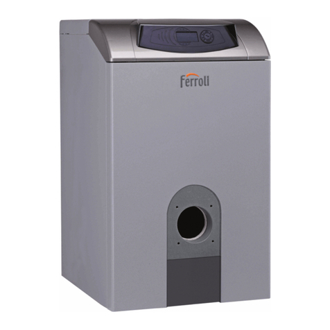
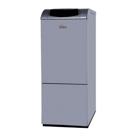
  9. Ferroli SIGMA User guide

Ferroli SIGMA User guide

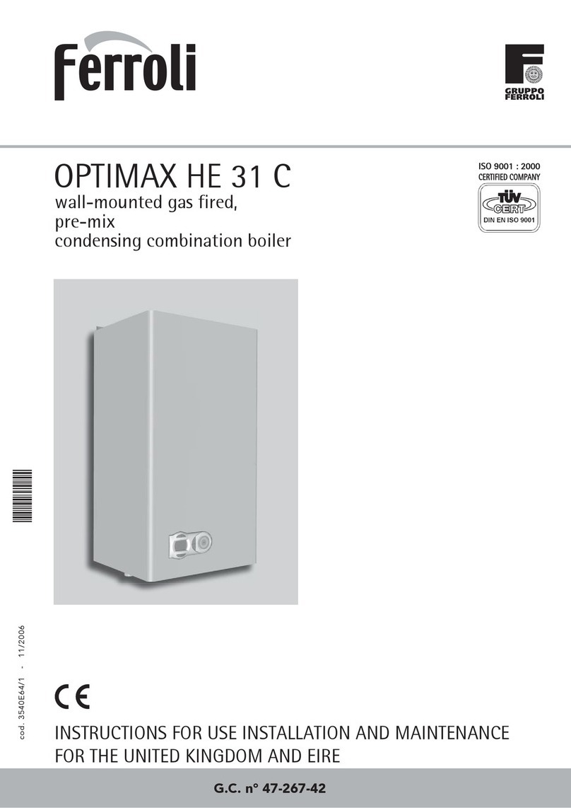
SIGM
INSTALLATION AND
SERVICING INSTRUCTIONS
Wall Mounted Cast Iron,
Gas Fired Boiler for Central Heating
Fan Assisted, Room Sealed,
Electronic Flame Ignition and Control
cod. 3543556/0 - 10/2001
Sigma 20 -40 GC N°41-267-17
Sigma 40 -60 GC N°41-267-18
2
Sigma
INDEX PAGE
1. TECHNICAL CHARACTERISTICS .......................................................................................3
.INSTALLATION ...................................................................................................................
.COMMISSIONINGANDTESTING...................................................................................
.DJUSTMENT .................................................................................................................. 3
.GAS CONVERSION ..........................................................................................................
.MINTEN NCEND CLE NING..................................................................................
.REPLACEMENT OFPARTS...............................................................................................
.FAULT FINDING................................................................................................................3
.USERINSTRUCTINS......................................................................................................33
.O.S.H.H.
Materials used in themanufacture of this applianceare non hazardousand no special precautionsare
required when servicing.
IMPORTANT
Your "benchmark" Installation, Commissioningand Service Record LogBook will be enclosed in your
customer information pack. This record must be completed and left with the end user.
Ferroli is amember of theBenchmarkinitiativeand fullysupports theaimsof theprogramme. Benchmark
has been introduced to improvethestandardsof installation and commissioning of central heating
systemsin theUK and to encouragetheregular servicing of all central heating systemsto ensure
safetyand efficiency.
CEMARK
CE markdocuments that theFerroli gas appliances complywith therequirementcontained in European
directives applicable to them.
In particular,theappliances complywith thefollowing CEE directives and thetechnical specifications
provided from them:
•Gas appliances directive90/396
•Efficiencies directive92/42
•Low tension directive73/23(modified from the93/68)
•Electromagnetic compatibilitydirective89/396 (modified from the93/68)
3
Sigma
Fig. 1
Key
1 - Ø 22 mm flow outlet
2- Ø 22 mm return inlet
3- Ø 15 gas inlet
4- Rearair inlet/flue outlet
5- Topair inlet/Flue outlet
25
A
25
B 85
147
15
50
120 50
D
C
132
50
200
2
1
Front view
Right side view
220
Top view
3
4
600
620
200
78
5
Model
Sigma 20-40
Sigma 40-60
A
mm
320
400
B
mm
53
133
C
mm
35
30
D
mm
60
55
1. TECHNICAL CHARACTERISTICS
1.01 Introduction
The Sigma isdefinedas a“room sealed” boiler,all air requiredforcombustionistakenfrom outside the room in whichit
isinstalled. It isanew highperformance gas firedheat generator,whichisdesignedto provide indirect hot waterand/or
central heating.The cast ironheat exchangerissuitable foruse onfullypumpedhot water/central heatingsystems,
whichmaybe sealedoropenvented. Aspecial feature ofthisboilerisitsbuilt-in electronicflame ignitionandcontrol
unit makingburneroperationcompletelyautomaticandsafe.
The main componentsare as follows:
Cast ironheat exchangerspecificallyshapedforhighefficiency.
Ceramicfibre insulatedcombustionchamber
One stainless steel bladedburnerspecificallydesignedforthisboiler.
Fanfordischarge ofcombustionproductsandintake ofcombustionair.
Differential air pressure switch.Forsafetyreasons,thisensuresthe burnerignitesonlywhenthe fanis
functioningcorrectly.
Hermeticallysealedcompartment made from corrosion-resistant steel enclosingthe above components.
Combinationgas safetyvalve,complete withpressure stabiliser.
Central heatingflow temperature adjustment thermostat.
Overheat safetythermostat.
Electroniccontrol unit forautomaticflame ignitionandcontrol.
Central heatingflow temperature sensor.
1.02Dimension
4
Sigma
Protection
level
IP 40
IP 40
Boiler
water
contents
1,3
1,6
litres
Weight
30
35
kg
Model
15
15
Gas inlet
3
Ø
Return
2
Ø
22
22
22
22
Flow
1
Ø
3
3
bar
Max. working
pressure
C.H.circuit
Connections Gas valve
Ø 1/2”
Honeywell
VK 4105 A
VK 4105 A
Sigma 20/40
Sigma 40/60
Model
Sigma 20/40
Sigma 40/60
G31-LPG
mbar
37
37
20
20
G20-NG
mbar
Burner gas pressures
G31-LPG
Nominal
mbar
36
36
Minimum
mbar
9,0
16,0
Nominal
mbar
14,0
15,3
Minimum
mbar
3,1
6,4
Gas supply pressures
G20-NG
11,7
17,6
Max
kW Min
kW
5,5
11,4
13,0
19,5
Max
kW Min
kW
6,1
12,7
14,4
21,7
Max
kW Min
kW
6,8
14,1
Model
Sigma 20/40
Sigma 40/60
Heat
output
Heat
input
(net)
Heat
input
(gross)
G31-LPG
Ø
1,8
2,30
3,0
3,60
G20-NG
Ø
1,37
2,06
Max
0,64
1,34
Min
1,02
1,53
Max
0,48
0,99
Min
G20 m3/h-NG G31 kg/h-LPG
Injectors
(mm) Gas flow rates
N.B. • Maximum working temperature 82°C, adjustable between 60°C and 82°C.
1.03 Technicaldata
5
Sigma
1.04 General Layout and Main Components
Fig. 2
19
27
132
1 16 1
34
11
86
121
68
63
24
83
44
22 21 7
5
151
49
43
28
90
1091
Air in
C.H.
in
C.H.
out
Flue out
Gas in
1.05Boiler water flowdiagram
Fig. 3
Key
1 Fixing points
5Roomsealed compartment
7Inlet gas-cock
10 Central heating flowoutlet
11 Central heating return inlet
16Fan
19Combustion chamber
21Gas injector
22 Burner
24Sparkandsensorelectrode
27Cast iron heat exchanger
28Fluecollectorfromheat exchanger
34Central heating flow
temperature sensor
43Airpressure switch
44 Gas valve
49Safetyoverheat thermostat
63Central heating temperature setting
68Controlbox withP. C . B .
83Full sequence automaticcontrol
86Automaticcontrolreset switch
90Flueoutlet pressure test point
91Airpressure test point
121Boiler shut-down warning
132Fluegas deflector
151Drain tap
.1 .2
20
30
40
50
60
70
80
90
200
300
.3 .4 .5 .6 .7 .8 .9 2 31
100
10
Water flow rate (m3/h)
Pressure drop mm wg
2
1
1=Sigma 20-40
2=Sigma 40-60
Pressure loss diagram
6
Sigma
2. INSTALLATION
2.01 Important notices
Assembly, installation, first start up and maintenance must be carried out by competent persons only, in accordance
with all current technical regulations and directives.
Gas Safety(Installation &Use)Regulations:1996
In the interest ofsafety, it is the lawthat all gas appliances are installed by a competent person in accordance with the
above Regulations, Building Regulations/Building Standards Scotland, Codes ofPractice, current I.E.E. Regulations and
the byelaws ofthe Local Water Undertaking. Failure to comply with the Regulations may lead to prosecution;it is your
responsibility to ensure that the law is complied with.
This appliance must be installedstrictly in accordance withthese instructions andregulations:
The Gas Safety Regulations (Installations &Use)1996.
The Local Building Regulations.
The Building Regulations.
The Buildings Standards (Scotland -Consolidated)Regulations.
British Standards Codes ofPractice:
B.S. 5440 Part 12000 Flues
B.S. 5440 Part 21989 Air supply
B.S. 5449 1990 FORCEDCIRCULATION HOT WATER SYSTEMS
B.S. 6798 1987 INSTALLATION OFGASFIREDHOT WATER BOILERS
B.S. 6891 1989 GASINSTALLATIONS
B.S. 7671 1992 IEE WIRING REGULATIONS
B.S. 4814 1990 SPECIFICATION FOREXPANSION VESSELS
B.S. 5482 1994 INSTALLATION OFLPG
B.S. 7593 1992 TREATMENT OF WATER IN DOMESTIC HOT WATER CENTRAL HEATING SYSTEMS
Model Water Bye Laws
For Northern Ireland the rules in force apply
N.B.For Northern Ireland the rules in force apply.
Important -If the boiler is to be fitted in a timber framed building it should be fitted in accordance with
the institute ofgas engineers publication IGE/UP/1. If in doubt advice should be sought from the Local Gas
Region ofBritish Gas Plc.
2.01.01 Location ofBoiler
The installation ofthe Sigma must be on a suitable non-combustible load bearing wall which will provide an adequate fixing
for the boiler mounting bracket assembly. The location should be in an area where the water pipes will not be subjected
to frost conditions. In siting the boiler the following limitations must be observed:
The boiler may be installed in any room or internal space, although particular attention is drawn to the requirements ofthe
current I.E.E. wiring regulations and in Scotland the electrical provisions ofthe building regulations applicable in Scotland,
with respect to the installation ofthe boiler in a room or internal space containing a bath or shower.
Where a room sealed appliance is installed in a room containing a bath or shower any electrical switch or
appliance control utilising mains electricity must be situated so that it cannot be touched by a person using
the bath or shower.
2.01.02 Air Supply
The room or compartment in which the boiler is installed does not require a purpose provided vent when using
the standard concentric flue.
2.01.03Flue System
The boiler allows the flue outlet to be taken from the rear ofthe boiler, from either side or vertically.
It is absolutely essential, to ensure that products ofcombustion discharging from the terminal cannot re-enter
the building, or enter any adjacent building, through ventilations, windows, doors, natural air infiltration or
forced ventilation/air conditioning.
7
Sigma
Fig. 4a
Gas
Pump
Expansion
vessel
Cold water
1
3
2
Filling point
Note: A bypass must be fitted as far
as possible from the boiler if
thermostatic radiator valves
are fitted thoughout.
2.01.04 GasSupply
If necessary the local Gas supplier should be consulted,at the installationplanning stage,inorder to establish
the availability of anadequate supply of gas.
Anexisting service pipe must not be used without prior consultationwith the Local Gas supplier.
A gas meter canonly be connected by the Local Gas supplier,or by a Local Gas suppliers Contractor.
Installationpipes should be fitted inaccordance with BS6891-1988.
Appliance inlet working pressure must be 20mbar MINIMUM (Natural gas -G20) or 37mbar MINIMUM (LPG-G31).
Pipeworkfrom the meter to the combinationboiler must be of anadequate size.
Do not use pipes of a smaller size thanthe combinationboiler inlet gascockconnection.
The complete installationmust be tested for gas soundness and purged as described inBS6981-1988. All pipework
must be adequately supported.
2.02 WaterSystem(sealedsystems)
Centralheating
Detailed recommendations are giveninBS6798,BS5449,BS6700 and CP342Part 2. Pipeworknot forming part of the
useful heating suface should be insulated to prevent any heat losses or possible freezing (i.e. inroof spaces or ventilated
underfloor spaces). Draintaps should be positioned at the lowest point of the system inaccessible locations to permit
the whole system to be drained down. The draintaps should be inaccordance with BS2879. Copper tubing to BS2871,
Part 1is recommended for water carrying pipework. Pipeworkinhorizontal runs should have a gradient where possible
to facilitate the removal of air. Ensure that the boiler heat exchanger is not a natural point for air collection. A
typical sealed heating system illustrated infig. 4.
Typicalsealedfully pumpedheatingsystem
8
Sigma
To DHW taps
Static Head
min. 1 m
max. 150 mm
Isolating valve
Drain
Flow
Return
Open
Vent
Open
Vent
Motorised valve
28 mm
gravity DHW
Isolating valve
CH Pump
By-pass
Motorised valve
22 mm CH Radiator Radiator
28 mm
28 mm
15 mm
22 mm
Schematic layout for gravity DHW and pumped CH for Sigma Boiler
Fig.4b
9
Sigma
Important - If thermostatic radiator valves are fitted throughout a bypass must be fitted to ensure a minimum flow rate
through the boiler of 6 l/min. The bypass should be fitted as far as possible from the boiler.
2.02.01 Safety valve
Asafety valve complying with the requirements of BS 6750 Part 1must be fitted close to the boiler on the flow pipe by
means of a horizontal or vertically upward connection with no intervening valve or restrictions and should be positioned
to facilitate testing. The valve should be pre-set and nonadjustable to operate at a pressure of 3bar (45 Ibf/in2). It must be
arranged to discharge any water or steam through a pipe to a safe outlet position.
2.02.02 Pressure gauge
Apressure gauge of minimum range 0-4bar (0-60Ibf/in2) with a fill pressure indicator must be fitted to the system,
preferably at the same point as the expansion vessel in an easily visible position.
2.02.03Venting
Amethod of venting the system during filling and commissioning must be provided by fitting automatic air
vents or by venting manually.
2.02.04Expansion vessel
In a sealed system an expansion vessel complying with the requirements of BS 4814 must be fitted to the system
by means of a connection close to the inlet side of the circulating pump in accordance with the manufacturers
instructions,the connecting pipe being unrestricted and not less than 15 mm (1/2in)nominal size. The volume
of the vessel should be suitable for the system water content and the nitrogen or air charge pressure should
not be less than the system static head.
Further details of sealed system design can be obtained from BS 5449:Part 1and the British Gas publication entitled
Specifications for Domestic Wet Central Heating Systems.
2.02.05Watertreatment
If water treatment is used ferroli limited recommend only the
use of Fernoxor Sentinel water treatment products,which must
be used in accordance with the manufacturers instructions. For
further information contact:
FernoxManufacturing Co. LTD. Sentinel Division
Tandern house,Marlowe Way BetzDearborn LTD
Croydon,surrey,CRO 4YSWidnes,Cheshire WA88ND
Tel:08 70 5601 5000 Tel :0151 424 5351
Note - If the boiler is installed in an existing system any
unsuitable additives must be removed by thorough cleansing.
All systems should be cleansed according to B.S. 7593.
Note - In hard water areas treatment to prevent lime scale
may be necessary.
Note - It is important that the correct concentration of the
water treatment product is maintained in accordance with the manufacturers instructions.
2.03Gasconnection
Gas connection must be carried out using a rigid pipe.
The flow at the gas meter should be sufficient for the simultaneous use of all appliances connected to it. Connect
the gas supply to the boiler according to current regulations. The diameter of the gas cockleaving the boiler is not
the determining factor in choosing the diameter of the pipe between the appliance and the meter. This must be
selected in relation to length and pressure drop.
The whole of the gas installation including the meter should be inspected and tested for soundness and purged
in accordance with BS6891-1988.
VESSEL CHARGE
PRESSURE (bar)
INITIAL SYSTEM
PRESSURE (bar)
TOTAL WATER
CONTENT of SYSTEM
Litres
25
50
75
100
125
150
175
200
0.33
For syst. volumes other than
those given above, mult. the syst.
volume by the factor across.
0.5 1.0
EXPANSION VESSEL VOLUME (litres)
8.3
16.5
24.8
33.1
41.3
49.6
57.9
66.2
1.5
2.0
10.3
20.6
30.9
41.2
51.5
61.8
72.1
82.4
0.412
2.0
4.7
9.5
14.2
19.0
23.7
28.5
33.2
38.0
0.190
1.5
13.7
27.5
41.3
55.1
68.9
82.6
96.4
110.2
0.551
2.0
6.5
12.9
19.4
25.9
32.4
38.8
45.3
51.8
0.259
1.5
3.5
7.0
10.5
14.0
17.5
21.0
24.5
28.0
0.140
1.0
Sizingof expansion vessels:
10
Sigma
105 min
205 min
254,5
620
Ø*
A
Boiler
mounting
plate
810 min
147
5 min
100
200 min
200
200 min 610
100
Fig. 5
Model
Sigma 20-40
Sigma 40-60
A
320
400
B
60 min.
140 min.
C
120
200
2.04 Wall Mounting
2.04.01DrillingTemp late
80
111
Ø118
WARNING:
C.H. connection
on this side
A
135
B
230 min.620
200 min.
C
80
91
Ø90
A
135B
WARNING:
C.H. connection
on this side
200 min.
620
C
Ø90
350 min.
165 min.
Minimum clearances and drilling template for standard
rear flue.
Fig. 6aFig. 6b
Drilling template for orizontal concentric flue. Drilling template for two pipe system withorizontal
air inlet.
11
Sigma
2.04.02 Wall mountinginstructions for Rear Flue Application
1
Select suitable mounting position for
boiler. Refer to fig. 6 for dimensions and
minimum clearance. Using the template
or mounting plate mark flue outlet and
boiler mounting points.
Fig. 7
Drill four 10mm holes 70 mm deep to
accept the wall plug. Using a core drill
cut hole for the flue.
Drill cut a 118mm diameter hole if it
is possible insert the flue-pipe from
outside of the room;drill cut a 127 mm
diameter hole if to insert the flue-pipe
from inside of the room.
2
Fig. 8
Insert the plastic plugs.
3
Fig. 9
5a5b
Ø118
Fig. 11aFig. 11b
4a4b
Ø127
Fig. 10aFig. 10b
Insert flue-pipe from inside of the room (core drill 127 mm hole)...
... or insert flue-pipe from outside of the room (core drill 118mm hole).
12
Sigma
11
Mark the aluminium flue pipe at the point it is flush with
the mounting plate. Add 15 mm to this mark and cut the
aluminium inner flue pipe at this point.
10
Insert the aluminium flue pipe into white plastic outer flue,
making sure the aluminium pipe sits fullyand centrally
into the flue terminal.
Fig. 16Fig. 17
15 mm
Cut the outer flue flush with the flange on the hanging
plate.
Through plate into air tube,drill two holes and fixin place
using two selftapping screws n°6x6mm long.
89
Fig. 14Fig. 15
67
Position the wall plate on the wall. Fixplate to wall with the
square gasket between the wall and the plate use the large
diameter washers for the bolts ad screws.
Gentlypull back until wall seal is flush with the wall.
Fig. 12Fig. 13
13
Sigma
Fig. 21a
2.05 Top outlet flueconversion
Take off the four screws which fix the top sealed chamber
cover, remove the cover and gasket.
Fig. 22aFig. 22b
1
3
Fig. 21b
2
4
12 1314
Install the inner metal flue "a"into the
adapter "b".
Lift boiler with flue pipe in place,
engage inner and outer flue, slide into
position.
Make sure the inner flue is fullyengage
in the flue terminal, secure boiler with
two nuts and washers "a"and "b".
Fig. 18Fig. 19Fig. 20
Remove fan bypulling off electrical connections. Pull off air
pressure switch tubes from the air pressure switch. Remove
the two screws "b"and rotate the fan upward to disengage
it from the securing pin "a".
Rotate the fan upward to disengage it from the securing
pin "a". Remove the securing screw that locates the
fan nozzle extension to the fan and remove the nozzle
extension.
Rotate the cover and gasket through 90° and fit it to
the rear of the boiler to cover the original flue outlet.
Secure them both in place with the four screws removed
14
Sigma
9
10
Insert the correct restrictor.
(See section 2.07).
Fixthe restrictor with the two screws
"a"inside the pipe connection "b".
Fig. 27
Fig. 28
b
b
a
Refit wiringconnections to fan andair
pressure switch tubes ensuringcorrect
orientation. I.E. redtube to air pressure
switch connection with reddot (+)
andclear tube to air pressure switch
connection with no paint marking(-).
Fit the fan into the boiler rotating
the front upwards to engage with the
pin "a".
Secure with the screws "b".
Fig. 29
11
Boiler is fittedas standardwith Ø36 (Sigma 20-40) or Ø41 (Sigma 40-60) restrictor. Identifyon 2.07 the correct restrictor for
your flue system. Ifit is necessaryto change it. followinstructions at step7-10,ifnot,go to step11.
Remove the two screws "a"frompipe
connection "b".
Remove restrictor "c".
Remove fan mountingplate byundoing
the three fixingscrews "c".
c
d
c
d
d
-
c
For top outlet
Common
For rear outlet
For rear
outlet
For top
outlet
Fig. 23
78
Fig. 25Fig. 26
56
Fig. 24
Rotate the fan through 90°so that the fan nozzle points upward. Secure the fan
to the plate in the newposition usingscrews in position "d".
15
Sigma
2Example of direct roof flue outlet
and wall air inlet with 2 pipe system
3Example of concentric flue Ø100
with vertical outlet flue use.
Warning•Backexit with Air/Flue Tseparator
is not possible
Fig. 32
Fig. 33
Note •Bear in mind that the two concentric
pipes must slope downwards away from the
boiler at a rate of about 3mm/m to avoid
rainwater enteringthe boiler.Outside,the
pipes should protrude from the wall between
10and 60mm.
Warning•Backexit with coaxial bend is
not possible
1Example of concentric flue Ø100
with appliance bend use
2.06.01Examplesoftopflueconnection
Fig. 31
2.06 Topoutlet FlueConnection
Three different connection are available from top of the boiler,usingaccessories as reported on fig.30a,be c and
on examples a next page.
Fig. 30
Vertical Connection,concentric bend
and two pipe separator can be
supplied on request.
Topoutlet horizontal
concentricflue
Topoutlet two
pipesystem
Topoutlet vertical
concentricflue
123
Fig. 30aFig. 30bFig. 30c
16
Sigma
2.07 Restrictor and max flue length
2.07.01 Concentric Flue System
First table below shows the maximum flue lengths available for boilers with concentric systems.
For correct calculation remember to include the reduction for bend and flue terminals listed on second table.
Reduction for bend
100 mm concentric bend 90°
100 mm concentric bend 45°
125 mm concentric bend 90°
125 mm concentric bend 45°
1 m
0,5 m
0,5 m
0,25 m
Maximum flue
length permissible
100 mm concentric
Vertical *Horizontal
125 mm concentric
Vertical *Horizontal
100 mm
concentric
back exit
Sigma 20/40
Sigma 40/60 4 m 3 m 5 m 5 m 1 m
*For horizontal flueing the reduction for appliance bend are already included.
Sigma
20-40 Sigma
40-60
A
B
C
Restrictor pipe
configuration
L2m
L2m
1m 3mL
L1m
Ø39
Ø36
Ø39
Ø36
Ø36
Ø46
Ø41
Ø46
Ø41
Ø46L1m
Boiler is fitted as standard with Ø36and Ø46restrictor.
For instruction on changing restrictor refer to step7-10at pages 14.
L(max. 3m.)
L(max. 1 m.)
Fig. 34Fig. 35
To calculate the restrictor,identify your flue pipe configuration (A, Bor C) and
choose the correct restrictor diameter from the restrictor table below.
L(max. 4m.)
Fig. 36
AHorizontal concentric BBackconcentric CVertical concentric
17
Sigma
Tab. 3
2.07.02 Two pipe flue system
1.Utilise the pipes and fittings flows resistance tables on the following pages and calculate the total flow resistance in
metres-air, by adding the flow resistances of the components in the whole air-flue system, based on their position
(vertical or horizontal, air inlet or flue outlet).
Please note that the same fitting, identified by a one code (i.e. 1pipe diameter 80, code KWMA83A), can offer
different flow resistances if positioned as air inlet or flue outlet, if placed vertically or horizontally.
Theflow resistanceofthespecialtwo pipe flue-airadaptersdonot haveto beincludedinthecalculationas
they arealreadyincludedinthemaximumlengthcalculation.
MPORTANT:thepipes and fittingsflow resistance(reduction)havebeensummarisedonthefollowingpage. The
flow resistancevalues writtenreferonlyto Ferrolipipes and fittings.
2. Verify that the total flow resistance calculated is less or equal to 40 metre.
3. Choose the more suitable restrictor from table below.
DescriptionRef.
Connection for concentric pipe cod. KWMR52A1
N°of
pieces Length
reduction
Total
Air/Flue T separator cod. KWMA90U2
Male - Female flue Ø 80 mm
3
4
Flue bend 80 mm5
Air wall terminal outlet flue Ø806
Air wall terminal air Ø807
Air
Flue
Horizontal
Vertical
Horizontal
Vertical
//
already included
1
/
2
5
2,5
5
2
17,5
1
1
1
/
1
5
1
1
1
Totalflow resistance17,5 m:
use restrictorØ41
Tab. 5
1 m
Sigma 60
4
3
6
4
5
7
2
1
5 m
Exampleofcalculationforwall inlet/outlet with2pipe systemmaximumtotalflue length:40metres
Fig. 37
Use restrictor:
Total flow resistance
0 - 20 metres
20 - 30 metres
30 - 40 metres
Ø36
Ø39
Ø39
Sigma 20/40
Ø41
Ø46
Ø46
Sigma 40/60
18
Sigma
Pipe and fittings reduction table (shown in Metres)
19
Sigma
Fig. 39
101 X4 X5
121 86
63
141 5
X8
GCP
JP
X3
Key
63. CH temperature setting
86. Reset switch
101.Main P. C .B.
121. Boiler shut-down warning (Led)
X3-X4-X5-X8.Connectors
JP.Link
Temp.
sensor
NTC 34
kOhm
1000 kOhm
185 kOhm
80 kOhm
Temp.
25°C
60°C
82°C
2.07.03 TerminalPosition
Fig. 38
2.08Electricalconnection
The boiler must be connectedtoa single phase 230V 50Hzelectricitysupplywitha 3Amax.fuse anda bipolar switch
withcontact opening ofat least 3mm fittedbetween the boiler andthe electricitysupply.The boiler must always be
connectedtoan efficient earthinstallation.In the electricalbox, there is a 3pole terminalblockfor connecting the
boiler tothe mains (230V 50Hz)anda 3pole blockfor connecting a
circulating pump (not supplied).See Wiring diagram (fig.41a)for the
connection ofexternalcontrol.
When the boiler is connectedtoan electricitymain,it is essentialTO
ENSURE CORRECTPOLARITY(LIVE: brown cable,NEUTRAL:blue
cable,EARTH:yellow-green cable).
All wiring must conform tocurrent I.E.E.regulations.
Note:If the power supplycable has tobe replaced,use “0.75mm
(24/0.20)cable onlytoBS6500 witha maximum external
diameter of8mm.
P
D, E
Q
Q
l
BC
A
G
F
L
J
HH
K
N
N
MM
Q
Directly below an opening, air brick, (0-7 kW)
opening windows, etc. (>7-14 kW)
(>14-32 kW)
(>32-70 kW)
Above an opening, air brick, (0-7 kW)
opening windows, etc. (>7-14 kW)
(>14-32 kW)
(>32-70 kW)
Horizontally to an opening, air brick, (0-7 kW)
opening windows, etc. (>7-14 kW)
(>14-32 kW)
(>32-70 kW)
Below gutters, soil pipes or drain pipes
Below eaves
Below balconies or car port roof
From a vertical drain pipe or soil pipe
From an internal or external corner
Above ground roof or balcony level
From a surface facing the terminal
(also see 6.1.2)
From a terminal facing the terminal
From an opening in the car port ( e.g. door,
window) into the dwelling
Vertically from a terminal on the same wall
Horizontally from a terminal on the same wall
From the wall on which the terminal is mounted
From a vertical structure on the roof
Above intersection with roof
Dimensions Terminal position
(kW input expressed in net)
Balanced flues room
sealed Open flues
Natural
draught Natural
draught
Fanned
draught Fanned
draught
Aa300 mm
600 mm
1500 mm
2000 mm
300 mm Not allowed 300 mm
Ba300 mm
300 mm
300 mm
600 mm
300 mm Not allowed 300 mm
Ca300 mm
400 mm
600 mm
600 mm
300 mm Not allowed 300 mm
D300 mm 75 mm Not allowed 75 mm
E300 mm 200 mm Not allowed 200 mm
F600 mm 200 mm Not allowed 200 mm
G300 mm 150 mmbNot allowed 150 mm
H600 mm 300 mm Not allowed 200 mm
I300 mm 300 mm Not allowed 300 mm
J600 mm 600 mm N/A 600 mm
K600 mm 1200 mm N/A 1200 mm
L1200 mm 1200 mm N/A 1200 mm
M1500 mm 1500 mm N/A 1500 mm
N300 mm 300 mm N/A 300 mm
ON/A N/A N/A 50 mm
PN/A N/A See Table 2
and Fig. 6b N/A
QN/A N/A See Table 2
and Fig. 4 150 mm
NOTE N/A = Not applicable
aIn addition, the terminal should not be nearer than 150 mm (fanned draucht) or 300 mm (natural draught) to an opening in the building fabric formed for the purpose of accommodating
a built-in element such as a window frame, (see Figure C2). Separation distances are linked to the rated heat inputs as shown.
bThis dimension may be reduced to 75 mm for appliances of up to 5 kW heat input.
Aapprovedterminalguard(part.No.C2 )should be screwed
tothe wall centrallyover the terminal,when the distance
is less than 2m from the outside floor.
20
Sigma
101 X4 X5
63
121 86
141 5
16
49
43
NO NC
C
123456789101112
83
24
32
72
SwL L N PL PN
230V ~
50 Hz
W
Blue
BR
BL
YGYG
Blue
BR
V
G
Blue
BL
BL
W
RW
O
P
BR
Blue
X8
GCP
JP
Fully
pumped
X3
34
2.08.01 Schematic wiringdiagram for fully pumped system
Key
16Fan
24Spark andsensor electrode
32Centralheatingpump(not fitted)
34Centralheatingflowtemperature sensor
43Airpressure switch
49Safetythermostat
63C.H. temperature adjustment
72Externalcontrols
83Full sequence automaticcontrol on gasvalve
86Reset switch
101 Main P.C.B.
121 Boiler shut-down warning(Led)
Fig. 40a
If there are no external
controls fitted,connect the
SWL terminal to permanent
live in the junction box
Colors key
BR Brown
Blue Blue
BLBlack
WWhite
OOrange
GGrey
RRed
VViolet
PPink
YGYellow-Green

Other manuals for SIGMA

3

This manual suits for next models

6

Other Ferroli Boiler manuals

Ferroli DIVATOP D HF Technical manual

Ferroli

Ferroli DIVATOP D HF Technical manual

Ferroli OPTIMAX 25 OV Troubleshooting guide

Ferroli

Ferroli OPTIMAX 25 OV Troubleshooting guide

Ferroli DOMIcompact F 24 B Parts list manual

Ferroli

Ferroli DOMIcompact F 24 B Parts list manual

Ferroli ECONCEPT 50 A User manual

Ferroli

Ferroli ECONCEPT 50 A User manual

Ferroli ATLAS D ECO SI UNIT Troubleshooting guide

Ferroli

Ferroli ATLAS D ECO SI UNIT Troubleshooting guide

Ferroli ECONCEPT TECH 25 A Troubleshooting guide

Ferroli

Ferroli ECONCEPT TECH 25 A Troubleshooting guide

Ferroli Divatop ST F 24 Manual

Ferroli

Ferroli Divatop ST F 24 Manual

Ferroli Optimax 25C- Modena HE Parts list manual

Ferroli

Ferroli Optimax 25C- Modena HE Parts list manual

Ferroli NEW CONDENS FS 300 SERIES User manual

Ferroli

Ferroli NEW CONDENS FS 300 SERIES User manual

Ferroli ECONCEPT TECH 25 A Troubleshooting guide

Ferroli

Ferroli ECONCEPT TECH 25 A Troubleshooting guide

Ferroli BLUEHELIX PRO S 32C Troubleshooting guide

Ferroli

Ferroli BLUEHELIX PRO S 32C Troubleshooting guide

Ferroli Domina 80 E Manual

Ferroli

Ferroli Domina 80 E Manual

Ferroli BlueHelix HiTech RRT C User manual

Ferroli

Ferroli BlueHelix HiTech RRT C User manual

Ferroli BLUEHELIX TECH S 45H User manual

Ferroli

Ferroli BLUEHELIX TECH S 45H User manual

Ferroli SF Troubleshooting guide

Ferroli

Ferroli SF Troubleshooting guide

Ferroli ATLAS D 37 K 130 UNIT Technical manual

Ferroli

Ferroli ATLAS D 37 K 130 UNIT Technical manual

Ferroli GN2 N User manual

Ferroli

Ferroli GN2 N User manual

Ferroli T-ONE User manual

Ferroli

Ferroli T-ONE User manual

Ferroli ENERGY TOP W 80 Troubleshooting guide

Ferroli

Ferroli ENERGY TOP W 80 Troubleshooting guide

Ferroli BLUEHELIX TECH RRT H Troubleshooting guide

Ferroli

Ferroli BLUEHELIX TECH RRT H Troubleshooting guide

Ferroli ATLAS D 30 K 100 UNIT Troubleshooting guide

Ferroli

Ferroli ATLAS D 30 K 100 UNIT Troubleshooting guide

Ferroli ECONCEPT TECH 35 A Troubleshooting guide

Ferroli

Ferroli ECONCEPT TECH 35 A Troubleshooting guide

Ferroli DIVAcondens F24 Troubleshooting guide

Ferroli

Ferroli DIVAcondens F24 Troubleshooting guide

Ferroli ECONCEPT 100 Troubleshooting guide

Ferroli

Ferroli ECONCEPT 100 Troubleshooting guide

Popular Boiler manuals by other brands

Gorenje TEG 5 Series Instructions for use

Gorenje

Gorenje TEG 5 Series Instructions for use

Slant/Fin Q3-4 Supplemental instructions

Slant/Fin

Slant/Fin Q3-4 Supplemental instructions

Worcester Greenstar 1000 User instructions

Worcester

Worcester Greenstar 1000 User instructions

Harman PB 105 Installation & operating manual

Harman

Harman PB 105 Installation & operating manual

Olsen OMGC-8D Installation, operation & maintenance manual

Olsen

Olsen OMGC-8D Installation, operation & maintenance manual

Viessmann VB2 Series Start-up/service instructions

Viessmann

Viessmann VB2 Series Start-up/service instructions

Electro Industries EB-MO-10 Installation & operating instructions

Electro Industries

Electro Industries EB-MO-10 Installation & operating instructions

Slant/Fin VICTORY II VHS Series Specifications

Slant/Fin

Slant/Fin VICTORY II VHS Series Specifications

Metal-Fach SE MAX II Technical And Operating Manual

Metal-Fach

Metal-Fach SE MAX II Technical And Operating Manual

FULTON Endura EDR-750 Installation and operation manual

FULTON

FULTON Endura EDR-750 Installation and operation manual

Hyco Omega OMEG3 Product instruction manual

Hyco

Hyco Omega OMEG3 Product instruction manual

Crown Boiler CXE-2 installation instructions

Crown Boiler

Crown Boiler CXE-2 installation instructions

Weil-McLain WM97+ Aqua Logic User's information manual

Weil-McLain

Weil-McLain WM97+ Aqua Logic User's information manual

Slant/Fin VGH-80-CH User's information manual

Slant/Fin

Slant/Fin VGH-80-CH User's information manual

Rinnai E32S Installation & servicing instructions

Rinnai

Rinnai E32S Installation & servicing instructions

Warmhaus LAWA Installation & user manual

Warmhaus

Warmhaus LAWA Installation & user manual

Vaillant ecoTEC plus Instructions for installation and servicing

Vaillant

Vaillant ecoTEC plus Instructions for installation and servicing

Riello INSIEME EVOe 25 B/70 LN Installation and maintenance manual

Riello

Riello INSIEME EVOe 25 B/70 LN Installation and maintenance manual

manuals.online logo
manuals.online logoBrands
  • About & Mission
  • Contact us
  • Privacy Policy
  • Terms and Conditions

Copyright 2025 Manuals.Online. All Rights Reserved.