FFC V-Snow Blade User manual

1
V-Snow Blade
800-456-7100 www.paladinlcg.com 2800 N. Zeeb Rd., Dexter, MI. 48130 United States of America
Model Number_______________________
Serial Number___________________________
Manual Number: 51-4320
Release Date: December 2010
Serial Number 1052001 and Up
OPERATOR'S & PARTS MANUAL

2
Notes

3
TABLE OF CONTENTS
PREFACE.....................................................................................................................................................4
SAFETY STATEMENTS...............................................................................................................................5
GENERAL SAFETY PRECAUTIONS........................................................................................................5-7
EQUIPMENT SAFETY PRECAUTIONS ......................................................................................................8
SAFETY DECALS & LABELS ......................................................................................................................9
INSTALLATION .........................................................................................................................................10
OPERATION..........................................................................................................................................11-19
MAINTENANCE SCHEDULE.....................................................................................................................20
MAINTENANCE RECORD.........................................................................................................................21
MAINTENANCE ...................................................................................................................................22-23
TROUBLESHOOTING ..........................................................................................................................24-28
PRODUCT SPECIFICATIONS ...................................................................................................................47
BOLT TORQUE SPECIFICATIONS ...........................................................................................................48
HYDRAULIC TORQUE SPECIFICATIONS...........................................................................................49-50
WARRANTY ...............................................................................................................................................51

4
GENERAL INFORMATION
This product was carefully designed and manufactured to give you many years of dependable service.
Only minor maintenance (such as cleaning and lubricating) is required to keep it in top working condition.
Be sure to observe all maintenance procedures and safety precautions in this manual and on any safety
decals located on the product and on any equipment on which the attachment is mounted.
WARNING! Never let anyone operate this unit without reading the “Safety Precautions” and
“Operating Instructions” sections of this manual. Always choose hard, level ground
to park the vehicle on and set the brake so the unit cannot roll.
Unless noted otherwise, right and left sides are determined from the operator’s control position when facing
the attachment.
NOTE: The illustrations and data used in this manual were current (according to the information
available to us) at the time of printing, however, we reserve the right to redesign and change the
attachment as may be necessary without notication.
BEFORE OPERATION
The primary responsibility for safety with equipment falls to the operator. Make sure the equipment is
operated only by trained individuals that have read and understand this manual. If there is any portion of
this manual or function you do not understand, contact your local authorized dealer or manufacturer to
obtain further assistance. Keep this manual available for reference. Provide this manual to any new owners
and/or operator’s
SAFETY ALERT SYMBOL
This is the “Safety Alert Symbol” used by this industry. This symbol is used to warn of
possible injury. Be sure to read all warnings carefully. They are included for your safety and
the safety of others working with you.
SERVICE
Use only manufacturer replacement parts. Substitute parts may not meet the required standards.
Record the model and serial number of your unit on the cover of this manual. The parts department
needs this information to insure that you receive the correct parts.
SOUND AND VIBRATION
“Sound pressure levels and vibration data for this attachment are inuenced by many different parameters;
some items are listed below (not inclusive):
• prime mover type, age, condition, with or without cab enclosure and conguration
• operator training, behavior, stress level
• job site organization, working material condition, environment
Based on the uncertainty of the prime mover, operator, and job site, it is impossible to get precise machine
and operator sound pressure levels, or vibration levels for this attachment.”
PREFACE

5
DANGER! THIS SIGNAL WORD IS USED WHERE SERIOUS INJURY OR DEATH WILL RESULT IF
THE INSTRUCTIONS ARE NOT FOLLOWED PROPERLY.
WARNING! THIS SIGNAL WORD IS USED WHERE SERIOUS INJURY OR DEATH COULD RESULT
IF THE INSTRUCTIONS ARE NOT FOLLOWED PROPERLY.
CAUTION! THIS SIGNAL WORD IS USED WHERE MINOR INJURY COULD RESULT IF THE
INSTRUCTIONS ARE NOT FOLLOWED PROPERLY.
NOTICE! NOTICE INDICATES A PROPERTY DAMAGE MESSAGE.
THIS SYMBOL BY ITSELF OR USED WITH A WARNING WORD THROUGHOUT THIS
MANUAL IS USED TO CALL YOUR ATTENTION TO INSTRUCTIONS INVOLVING YOUR
PERSONAL SAFETY OR THE SAFETY OF OTHERS. FAILURE TO FOLLOW THESE
INSTRUCTIONS CAN RESULT IN INJURY OR DEATH.
SAFETY STATEMENTS
GENERAL SAFETY PRECAUTIONS
WARNING! READ MANUAL PRIOR TO INSTALL
Improper installation, operation, or maintenance of this equipment could result in serious
injury or death. Operators and maintenance personnel should read this manual as well as
all manuals related to this equipment and the prime mover thoroughly before beginning
installation, operation, or maintenance. FOLLOW ALL SAFETY INSTRUCTIONS IN THIS
MANUAL AND THE PRIME MOVERS MANUAL.
WARNING! READ AND UNDERSTAND ALL SAFETY STATEMENTS
Read all safety decals and safety statements in all manuals prior to operating or working
on this equipment. Know and obey all OSHA regulations, local laws and other professional
guidelines for your operation. Know and follow good work practices when assembling,
maintaining, repairing, mounting, removing or operating this equipment.
KNOW YOUR EQUIPMENT
Know your equipment’s capabilities, dimensions and operations before operating. Visually
inspect your equipment before you start, and never operate equipment that is not in proper
working order with all safety devices intact. Check all hardware to assure it is tight. Make
certain that all locking pins, latches, and connection devices are properly installed and
secured. Remove and replace any damaged, fatigued or excessively worn parts. Make
certain all safety decals are in place and are legible. Keep decals clean, and replace them if
they become worn and hard to read.
WARNING! PROTECT AGAINST FLYING DEBRIS
Always wear proper safety glasses, goggles or a face shield when driving pins in or out or
when operation causes dust, ying debris, or any other hazardous material.

6
WARNING! LOWER OR SUPPORT RAISED EQUIPMENT
Do not work under raised booms without supporting them. Do not use support material made
of concrete blocks, logs, buckets, barrels or any other material that could suddenly collapse
or shift positions. Make sure support material is solid, not decayed, warped, twisted, or
tapered. Lower booms to ground level or onto blocks. Lower booms and attachments to the
ground before leaving the cab or operator’s station.
WARNING! USE CARE WITH HYDRAULIC FLUID PRESSURE
Hydraulic uid under pressure can penetrate the skin and cause serious injury or death.
Hydraulic leaks under pressure may not be visible. Before connecting or disconnecting
hydraulic hoses, read your prime movers operator’s manual for detailed instructions on
connecting and disconnecting hydraulic hoses or ttings.
• Keep unprotected body parts, such as face, eyes, and arms as far away as possible from
a suspected leak. Flesh injected with hydraulic uid may develop gangrene or other
permanent disabilities.
• If injured by injected uid, see a doctor at once. If your doctor is not familiar with this type
of injury, ask him to research immediately to determine proper treatment.
• Wear safety glasses, protective clothing, and use a sound piece of cardboard or wood
when searching for hydraulic leaks.
DO NOT USE YOUR HANDS!
SEE ILLUSTRATION.
WARNING! DO NOT MODIFY MACHINE OR ATTACHMENTS
Modications may weaken the integrity of the attachment and may impair the function,
safety, life and performance of the attachment. When making repairs, use only the
manufacturer’s genuine parts, following authorized instructions. Other parts may be
substandard in t and quality. Never modify any ROPS (Roll Over Protection System)
equipment or device. Any modications must be authorized in writing by the manufacturer.
GENERAL SAFETY PRECAUTIONS

7
GENERAL SAFETY PRECAUTIONS
WARNING! SAFELY MAINTAIN AND REPAIR EQUIPMENT
•Do not wear loose clothing, or any accessories that can catch in moving parts. If you have
long hair, cover or secure it so that it does not become entangled in the equipment.
•Work on a level surface in a well-lit area.
•Use properly grounded electrical outlets and tools.
•Use the correct tool for the job at hand. Make sure they are in good condition for the task
required.
•Wear the protective equipment specied by the tool manufacturer.
WARNING! SAFELY OPERATE EQUIPMENT
Do not operate equipment until you are completely trained by a qualied operator in how to
use the controls, know its capabilities, dimensions, and all safety requirements. See your
prime movers manual for these instructions.
•Keep all step plates, grab bars, pedals, and controls free of dirt, grease, debris, and oil.
•Never allow anyone to be around the equipment when it is operating.
•Do not allow riders on the attachment or the prime mover.
•Do not operate the equipment from anywhere other than the correct operators position.
•Never leave equipment unattended with the engine running or with this attachment in a
raise position.
•Do not alter or remove any safety feature from the prime mover or this attachment.
•Know your work site safety rules as well as trafc rules and ow. When in doubt on any
safety issue, contact your supervisor or safety coordinator for an explanation.
EQUIPMENT SAFETY PRECAUTIONS
WARNING! EXPOSURE TO RESPIRABLE CRYSTALLINE SILICA DUST ALONG WITH OTHER
HAZARDOUS DUSTS MAY CAUSE SERIOUS OR FATAL RESPIRATORY DISEASE.
It is recommended to use dust suppression, dust collection and if necessary personal
protective equipment during the operation of any attachment that may cause high levels of
dust.
WARNING! REMOVE PAINT BEFORE WELDING OR HEATING.
Hazardous fumes/dust can be generated when paint is heated by welding, soldering or
using a torch. Do all work outside or in a well ventilated area and dispose of paint and
solvent properly. Remove paint before welding or heating.
When sanding or grinding paint, avoid breathing the dust. Wear an approved respirator.
If you use solvent or paint stripper, remove stripper with soap and water before welding.
Remove solvent or paint stripper containers and other flammable material from area. Allow
fumes to disperse at least 15 minutes before welding or heating.
WARNING! END OF LIFE DISPOSAL.
At the completion of the useful life of the unit, drain all fluids and dismantle by
separating the different materials (rubber, steel, plastic, etc.). Follow all federal, state
and local regulations for recycling and disposal of the fluid and components.

8
EQUIPMENT SAFETY PRECAUTIONS
Operating the V-Snow Blade:
•Do not exceed the lifting capacity of your prime mover.
•Operate only from the operator’s station.
•When operating on slopes, drive up and down, not across. Avoid steep hillside operation
which could cause the prime mover to over turn.
•Reduce speed when driving over rough terrain, on a slope, or turning to avoid overturning
the vehicle.
•An operator must not use drugs or alcohol, which can change his or her alertness or
coordination. An operator taking prescription or over-the-counter drugs should seek
medical advice on whether or not he or she can safely operate equipment.
•Before exiting the prime mover, lower the attachment to the ground, apply the brakes, turn
off the prime mover’s engine and remove the key.
Transporting the V-Snow Blade:
•Travel only with the attachment in a safe transport position to prevent uncontrolled
movement. Drive slowly over rough ground and on slopes.
•When driving on roads use safety lights, reflectors, Slow Moving Vehicle signs etc. to
prevent accidents. Check local government regulations that may affect you.
•Do not drive close to ditches, excavation, etc. cave in could result.
Maintaining the V-Snow Blade:
•Before performing maintenance (unless otherwise specified) lower the attachment to the
ground, apply the brakes, turn off the engine and remove the key.
•Never perform any work on the attachment unless you are authorized and qualified to do
so. Always read the operator service manual’s before any repair is made. After completing
maintenance or repair, check for correct functioning of the attachment. If not functioning
properly, always tag “DO NOT OPERATE” until all problems are corrected.
•Worn, damaged or illegible safety decals must be replaced. New safety decals can be
ordered from FFC.
•Never make hydraulic repairs while system is under pressure. Serious personal injury or
death could result.
•Never work under a raised attachment.

9
SAFETY DECALS & LABELS
Use part numbers to order replacements for lost or damaged decals. Be sure to read all decals before
operating the attachment. They contain information you need to know for both safety and longevity.
Placement or replacement of Safety Signs
1. Clean the
area of application with nonammable solvent, and then wash the same area with soap and water.
2. Allow the surface to fully dry.
3. Remove the backing from the safety sign, exposing the adhesive surface.
4. Apply the safety sign to the position shown in the diagram above and smooth out any bubbles.
Instructions
1. Keep all safety signs clean and legible.
2. Replace all missing, illegible, or damaged safety signs.
3. Replacement parts, for parts with safety signs attached, must also have safety signs attached.
4. Safety signs are available, free of charge, from your dealer or from SWEEPSTER.
Item Part Qty Description
1. 50-0721 3 Label, Warning, Crush Hazard
2. RDL3132 2 Label,Amber,ReectiveTape,2x6
3. RDL3131 2 Label,Red,ReectiveTape,2x6
4. 50-0724 1 Label, Warning, High Pressure Fluid
5. 50-0737 1 Label,Warning,PinchPointHazard
6. 50-10017 1 Label,Warning,AvoidSeriousInjury
9. 50-0775 2 Label, Warning, Crush Hazard
4. 50-0724
1. 50-0721
5. 50-0737
6. 50-10017
9. 50-0775
2. & 3. RDL3132 & RDL3131
Serial
Number Tag

10
WARNING! Improper attachment of V-Snow Blade could result in injury or death. Do not operate
this machine until you have positive indication that the attachment is securely mounted.
1. Position the blade on a level surface.
2. Enter the prime mover.
3. Fasten the safety restraints.
4. Start the engine.
5. Disengage the parking brake.
6. Align the attachment mechanism with the mounting on the blade and attach it to the prime mover.
Follow the attaching procedure in the prime mover owner’s manual.
7. Engage the parking brake and shut down the prime mover. Relieve all pressure to the auxiliary
hydraulic lines.
8. Unfasten safety restraints and exit the prime mover.
9. Ensure that the hydraulic quick couplers are clean. Connect hydraulic lines for the blade to the prime
mover. Twist the collar of the quick couplers one quarter of a turn, to secure the hydraulic connection.
10. While the loader arms are lowered, visually inspect the attachment mechanism to ensure that it is
securely mounted.
11. Enter prime mover, fasten safety restraints and start prime mover.
12. Carefully raise the loader and cycle the rollback/dump cylinders to check clearances, that limiting
stops make proper contact and verify that all mounting procedures have been successfully completed.
Contact FFC for instructions if the limiting stops do not contact properly.
INSTALLATION
V-Snow Blade Installation

11
INSTALLATION
Removing the V-Snow Blade
WARNING! Serious injury or death may result from disengaging the blade when the blade is
in an unstable position. Place blade on a rm, level surface in a stable position before
disengaging.
NOTICE! HOSES FOR THE BLADE MUST BE REMOVED BEFORE THE QUICK ATTACH IS
DISENGAGED. Pulling the blade with the hoses could result in damage to the prime mover
or to the blade.
1. Position the blade on a level surface.
2. Congure the blade in either the “scoop” or “straight” position (for positions refer to angling instructions
in operations). Never disengage the blade when it is in the “V” position.
3. Lower the blade to the ground.
4. Tilt the blade until the mounting is on the ground.
5. Engage the parking brake and shut off the prime mover. Relieve the pressure to the auxiliary hydraulic
lines.
6. Unfasten safety restraints and exit prime mover.
7. Disconnect the blades hydraulic lines from the prime mover and connect the quick couplers together to
keep them clean.
8. Disengage attachment locking mechanism (consult prime mover manual).
9. Enter prime mover, fasten safety restraints and start the prime mover.
10. Disengage the parking brake and back away the blade.
WARNING! AFTER BACKING AWAY BE SURE BLADE MOUNTING IS CONTACTING THE GROUND.
If not in contact with ground, blade will be unstable and serious injury or death may occur.

12
INTENDED USE:
This blade is designed solely for the use in snow removal. This blade is not designed to move dirt, loose
soil or gravel. Use in any other way is considered contrary to the intended use. Compliance with and strict
adherence to operation, service and repair conditions as specied by the manufacturer, are also essential
elements of the intended use.
CAUTION! A V-SNOW BLADE IS A DEMANDING MACHINE. Only fully trained operators or trainee
operators under supervision of a fully trained person should use this machine.
Before operating blade
•Learn blade and prime mover controls in an off-road location.
•Be sure that you are in a safe area, away from trafc or other hazards.
•Check all hardware holding the blade to the host machine, making sure it is tight.
•Replace any damaged or fatigued hardware with properly rated fasteners.
•Make sure all hydraulic hardware and hydraulic ttings are tight.
•Replace any damaged or fatigued ttings or hoses.
•Remove from the plowing area all property that could be damaged by ying debris or impacts from the
blade.
•Be sure all persons not operating the blade are clear of the area being cleared.
•Always wear proper apparel; such as safety glasses, goggles or a face shield and ear protection.
While operating blade:
•When operating the blade, adhere to all government rules, local laws and other professional guidelines
for your plowing application.
•Before leaving the operators area for any reason, lower the blader to the ground. Stop the prime
mover engine, set the brakes and remove the key from the ignition.
•Keep hands, feet, hair and other loose clothing away from all moving parts.
•Leave all shields and safety equipment in place when operating the blade.
•Be aware of extra weight and width a blade adds. Reduce travel speed accordingly.
•When operating on rough terrain, reduce speed to maintain control of steering.
•Never plow toward people, buildings, vehicles or other objects that can be damaged by ying
debris.
OPERATION

13
Hydraulic Sequencing Model
Adjusting V-Blade:
1. Start the prime mover at idle and raise the blade.
2. Adjust the blade to the desired angle (refer to “angling instructions”) and then lower to the ground.
3. Adjust blade until it is level to the ground ( refer to “leveling instructions”).
4. Increase prime mover engine rpm to operating speed.
Angling Instructions:
•Only operate the blade while you are in the seat of the prime mover. The seat belt must be
fastened while you operate the prime mover. Only operate the controls while the engine is running.
Protective glasses must be worn while you operate the prime mover and while you operate the
blade.
•While you operate the blade slowly in an open area, check for proper operation of all controls and
all protective devices. Note any repairs needed during operation of the blade. Report any needed
repairs.
OPERATION
SCOOP
LEFT ANGLE
Scoop Position:
Hold hydraulic ow until both blades extend
and stop.
Left Angle Position:
If starting in “V” position, hold hydraulic ow
until right blade extends and stops.
14
OPERATION
STRAIGHT
Straight Position:
1. If starting from the scoop position, reverse
ow until right blade completely retracts.
2. While still reversing ow, retract left blade
until it is in the straight position.
3. Use normal ow to extend right blade until
it is parallel to left blade.
V Position:
Reverse ow until both blades retract and
stop.
Right Angle Position:
If starting from the Scoop position, reverse
ow until right blade retracts and stops.
V
RIGHT ANGLE

15
OPERATION
Electro-Hydraulic Model
Adjusting V-Blade:
1. Start the prime mover at idle and raise the blade.
2. Adjust the blade to the desired angle (refer to “angling instructions”) and then lower to the ground.
3. Adjust blade until it is level to the ground ( refer to “leveling instructions”).
4. Increase prime mover engine rpm to operating speed.
Angling Instructions:
1. Press toggle switch and hold ow to move
one blade to the desired position.
2. Release switch and ow.
3. Pull toggle switch and hold ow to move
other blade to the desired position.
4. Release switch and ow.

16
OPERATION
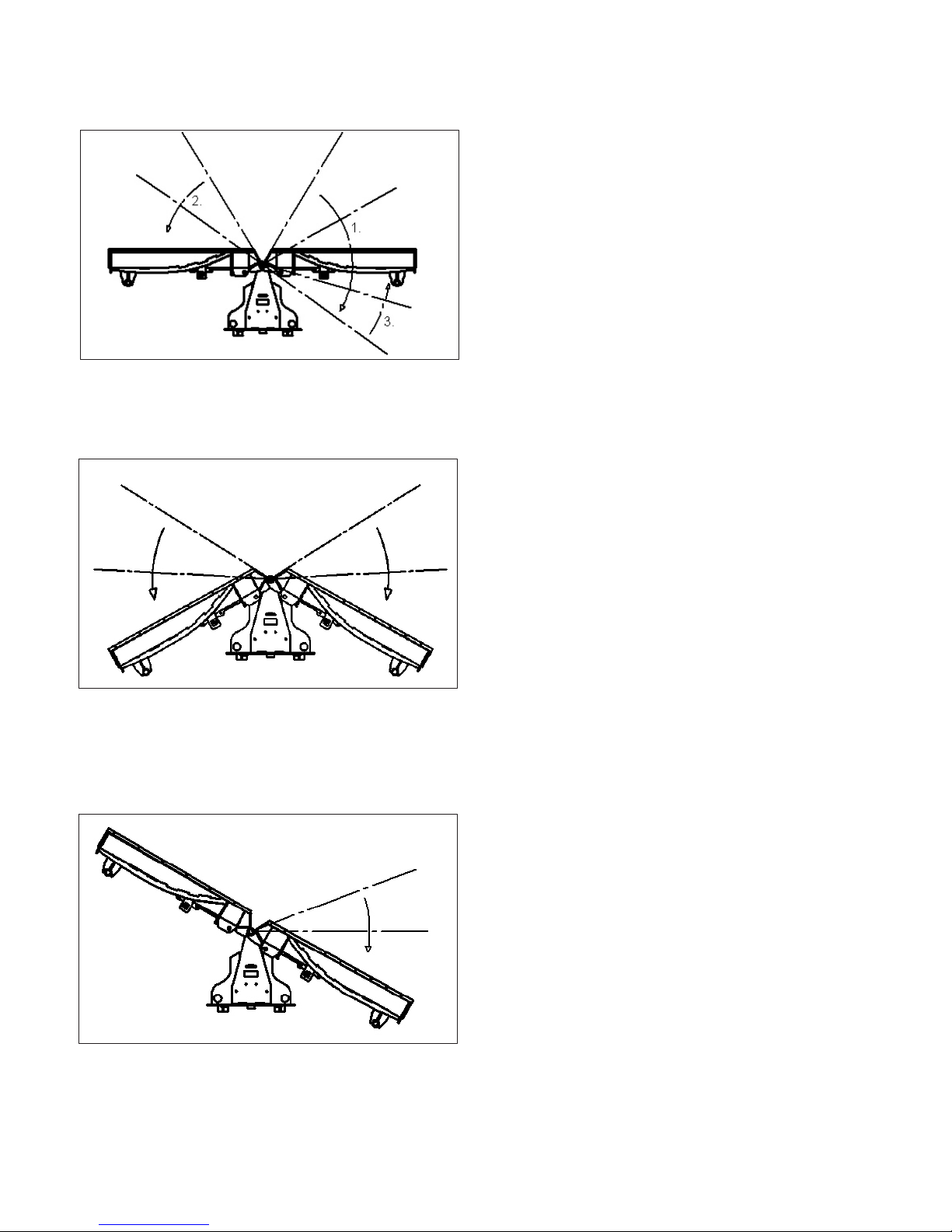
Leveling Instructions
NOTICE! A LEVEL UNIT SHOULD HAVE NO VISIBLE SPACES BETWEEN CUTTING EDGES AND
PLOWING SURFACE.
Scoop Position
If the front corners of the attachment are contacting the plowing surface and a gap is visible towards the
center of the attachment (gure 2):
1. Lift attachment
2. Roll attachment backwards
3. Lower back to ground
4. Continue until level.
If the rear center of the attachment is contacting the plowing surface and a gap is visible towards the outer
sides of the attachment (gure 3):
1. Lift attachment
2. Roll attachment forward
3. Lower back to ground
4. Continue until level
V Position
If the front corner of the attachment is contacting the plowing surface and a gap is visible towards the outer
sides of the attachment (gure 2):
1. Lift attachment
2. Roll attachment backwards
3. Lower back to ground
4. Continue until level.
If the outer sides of the attachment are contacting the plowing surface and a gap is visible towards the
center of the attachment (gure 3):
1. Lift attachment
2. Roll attachment forward
3. Lower back to ground
4. Continue until level

17
OPERATION
gure 2
gure 3
Level
Scoop Position Shown

18
OPERATION
1. Move prime mover to a level surface with the blade properly attached.
2. Place the prime mover in “Park” and engage the parking brake.
3. Lower the blade onto the level surface.
4. Shut off prime mover engine, remove key and relieve all pressure from the hydraulic lines.
5. Check spring specications on chart below.
RECOMMENDED SPRING SET-UP LENGTHS
Blade Width 60 in 72 in 84 in 96 in 108 in 120 in
Recommended Spring Set-up Length* 14.38 inches
Maximum Length Permitted- 15.33 inches
6. Test snow blade. If edges trip too easily, perform the following steps:
a. Repeat the above steps 1 through 4.
b. Tighten the spade (or eye) bolts to lengthen the springs.
WARNING! LENGTHENING THE SPRINGS BEYOND THE MAXIMUM
LENGTH PERMITTED CAN RESULT IN DAMAGE TO THIS
PRODUCT.
c. Test your blade again. If edges still trip too easily contact FFC.
*NOTE: The Spring set-up lengths are measured from the inside of one hook to the inside of the
other hook. The relaxed length of the spring is 14 inches.

19
OPERATION
Skid Shoe Set-Up
Determine what type of surface is beneath the snow where your blade is being operated.
If the surface is hard and smooth, like concrete or asphalt, the skid shoe placement as shipped from the
factory is correct. (3 spacers on top, 16 on bottom)
If the surface is soft or uneven, then lower the shoe to the desired position (see directions and diagram
below).
Changing the position of the skid shoe :
1. Park the prime mover on a rm, level surface with blade properly attached
2. Lower the blades cutting edge onto a sturdy wood or metal blocking to safely hold the skid shoes 2.5 to
3 inches off the level surface.
3. Place prime mover in “Park” and engage parking brake.
4. Shut off the prime mover’s engine, remove the key and relieve all pressure from hydraulic lines.
5. Remove the lynch pin securing the skid shoe.
6. Adjust the positioning of the spacers to raise or lower the skid shoe.
7. Re-secure the lynch pin.
8. Repeat for the other skid shoe.
NOTICE! WHEN ADJUSTING THE SKID SHOE, ALL SPACERS MUST BE USED.
Factory Settings
(3 on Top, 16 on Bottom)

20
CAUTION ! DO NOT MODIFY THE V-SNOW BLADE IN ANY WAY. Personal injury could result. If you
have questions, contact your dealer or FFC.
Repair or adjust the blade in a safe area, away from trafc and other hazards.
Before adjusting or servicing, lower the blade to the ground, set parking brake, shut down the prime
mover and remove the key from the ignition.
When working on or around the blade, safely secure it from falling or shifting.
Service & Repair - Hydraulic Safety
Stop the prime mover engine and release hydraulic pressure before servicing or adjusting blade hydraulic
systems.
WARNING! Escaping hydraulic uid can have enough pressure to penetrate the skin, causing
serious personal injury.
Check lines, tubes and hoses carefully. Do not use your hand to check for leaks. Use a board or cardboard
to check for leaks. Tighten all connections to the recommended torque.
Do not bend high pressure lines. Do not strike high pressure lines, Do not install bent lines, bent tubes, or
kinked hoses. Do not install damaged lines, tubes, or hoses.
Repair loose lines, tubes, and hoses. Replace damaged lines, tubes, and hoses. Leaks can cause res.
See your dealer for repair or replacement parts.
Replace the parts if any of the following conditions are present:
• The end ttings are damaged or leaking.
• The outer covering is chafed or cut.
• The reinforcing wire layer is exposed.
• The outer covering is ballooning locally.
• The hose is kinked or crushed.
• The hose has been pulled or stretched.
Make sure that all clamps, guards, and shields are installed correctly.
Service & Repair
OPERATION
Table of contents
Other FFC Snow Blower manuals


