FFD POWER SOLE 5000 User manual

Installation and User Manual
51.2V/100AH LiFePO4 battery for solar energy storage
SOLE 5000

ATTENTION: The battery could explode and/or be severely damaged if
dropped or crushed.
ATTENTION: Appropriate mechanical lifting equipment must be used since the
Battery Module weighs 126.3 lb /57.3 kg
ATTENTION: The battery may explode if exposed to open flames or other ex-
treme sources of heat.
ATTENTION: The battery terminals must be disconnected before commencing
any work on the battery.
ATTENTION: This battery can accumulate parasite current. Do not touch the
B+ and B- terminals. Always check the B+ and B- terminals with a voltmeter.
Always ensure that there are ZERO volts present on the terminals before per-
forming any operation on the battery.
ATTENTION: Always wear Individual protection devices, use insulated tools,
and follow the safety plan of this manual. At end of life, these batteries must be
disposed of properly by a certified professional company.
At end of life, these batteries must be disposed of properly by a certified
professional company.
Statement:
The information and guidance contained in this manual is related to the SOLE 5000 low level model of battery.
In case of product upgrades or other reasons, this document will be adjusted accordingly. Unless otherwise agreed, this
document is intended to be used only as a guide, and all statements, information and advice in the documentation shall not
constitute any express or implied action in contradiction to local regulations or standards.
For more information, please contact us.
The official information and the latest datasheet are available on www.ffdpower.com
It is essential that the Battery Module is equipped with the latest firmware version available.
New batteries always ship with the latest version of firmware.
From time to time, firmware will be updated to improve the functionalities and battery capabilities. The latest version of
the firmware is always available free of charge and can be updated by your local installer. You can always contact in-
fo@ffdtec.com for additional information on the upgrade procedure.
NOTICE: This Battery Module is designed to be used indoors. The standard IP21
degree of protection does not allow installation in outdoor environments even if
sheltered from the weather. The Battery Modules must be stored indoors in a clean,
dry, cool location in a limited access area
Preface:
Thank you for choosing our product. We will provide you with a high-quality product as well as reliable after-sale service.
To protect against harm to both personnel and the product, please read this manual carefully.
This manual provides detailed information on operation, maintenance and troubleshooting of the product as well as health
and safety advice.
Declaration:
The manufacturer holds the right of final explanation of any content in this manual.
All trademarks shown in this manual belong to their legitimate owners; trademarks of third parties, product names, trade
names, corporate names and companies mentioned may be trademarks owned by their respective owners or registered
trademarks of other companies and are used purely for explanatory purposes and for the benefit of the owner, without any
purpose of violation of the copyright in force.

The System Design
System Design is the process of defining the architecture, components, modules, interfaces and load data for a system to
satisfy specified requirements.
For a solar energy system, these components are the PV modules, inverter/charge controller & batteries, as well as the
different interfaces of those components.
Battery Operation
There are several factors that affect the operation of the battery that could impact its ability to deliver capacity and life
expectancy.
Storage
Battery Module shall be stored in original packaging, in a clean, level, dry, cool location indoors.
Recommended storage temperature is 77°F (25°C).
The battery can be stored in the range of -4°F to +113°F (-20°C to +45°C) but it requires an inspection and recharge every
three months (max charging current is 0.1C).
Max SoC storage % is 50%.
Max Transportation SoC is 30% in accordance with UN 38.3 Prescriptions
Temperature
Many chemical reactions are affected by temperature, and this is true of the reaction that occurs in a storage battery.
The chemical reaction of a Li-Ion is slowed down by a lowering of the electrolyte temperature that results in less capacity.
A battery that will deliver 100% of rated capacity at 77°F (25°C) will only deliver approximately 75% of rated capacity at
+50°F (+10°C).
At temperatures down to +19.4°F (+7°C) the charge current may be limited to 0.1C depending on other factors, however
at temperatures below +19.4°F (-7°C) charging is restricted by the BMS.
As part of the Performance Warranty, Charge and Discharge shall be in the range +68°F to +77°F (+20°C to +25°C). Any
usage outside this range is not covered by Performance Warranty.
Depth of Discharge (DoD)
Depth of discharge is a function of design. The deeper the discharge per cycle, the shorter the life of the battery. A cycle is
a discharge and its subsequent recharge regardless of depth of discharge.
Charging
The majority of battery capacity/life issues can be traced to improper charging. Improper charging settings may lead to an
overcharging or undercharging condition.
Warranty
Although the BMS of the battery allows a wide range of use, both in terms of temperature and charging currents, this
should not be construed as an implicit authorization to use the battery at these levels. For the purposes of the Performance
Warranty, it is mandatory that the battery is used within the range of temperature and charge/discharge current, and Depth
of Discharge indicated in the Performance Warranty. Warranties only apply to batteries connected via BMS line to an
approved inverter. Any other use, even if permitted by the BMS ranges, is not covered by the Performance Warranty.
Product Overview
The FFD SOLE 5000 is a Stackable Battery that can be used in a Low Voltage configuration. For LOW VOLTAGE
(Max 58.4 Vdc)* Configuration Refer to Section 2 *Voltage ranges are estimates only as they always depend on interac-
tions with other devices and ambient conditions.
Information in this Manual
About this Manual This manual relates only to the FFD SOLE 5000 Stackable Battery Module. Only trained and quali-
fied installers should install, repair or charge these Battery Modules. This manual should be reviewed in its entirety for
proper storage, installation and operation of the Battery Module.
Use Range T
his installation guidance applies for the Low Voltage Inverters. Make sure to use the correct inverter charging parameters
before connecting to the battery. Each FFD SOLE 5000 Battery Module has two different circuits and depending on the
inverter voltage range, the installer must choose the correct battery configuration for that range.
Additional Information
Product specifications subject to change without notice.
Symbols Used
Symbol Meanings:
CAUTION represents hazardous situations which can cause injuries if not avoided.
NOTICE represents the situations which can cause damage to property if not avoided.
INFORMATION provides tips that are valuable for optimum installation and operation
of the product
Caution Information Notice
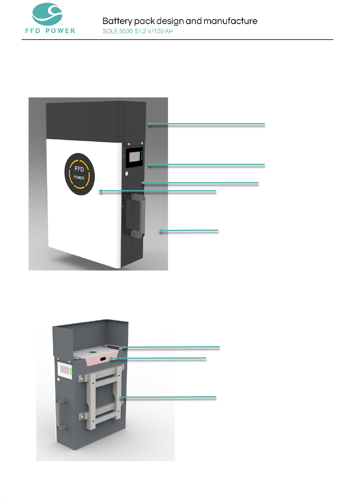
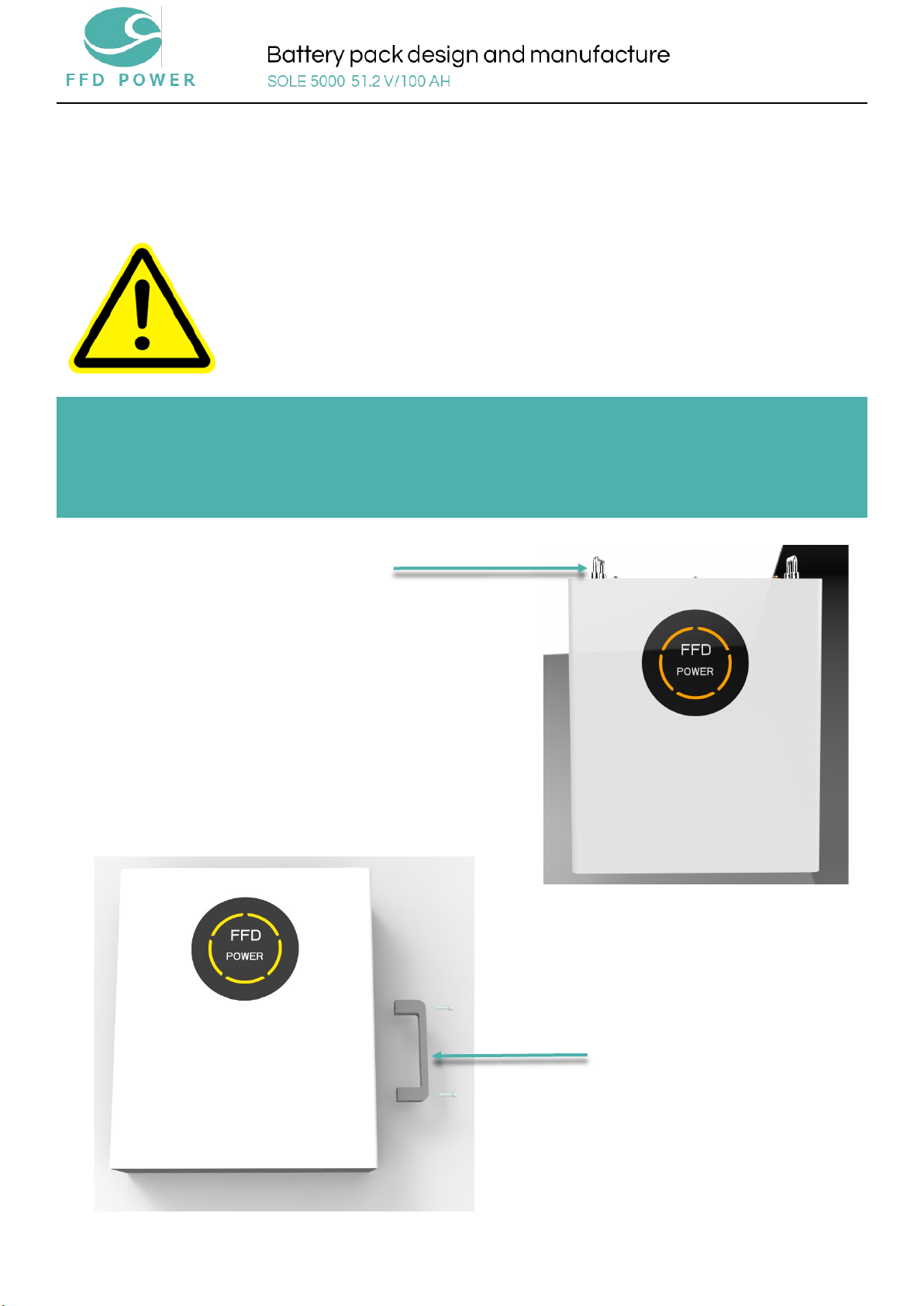
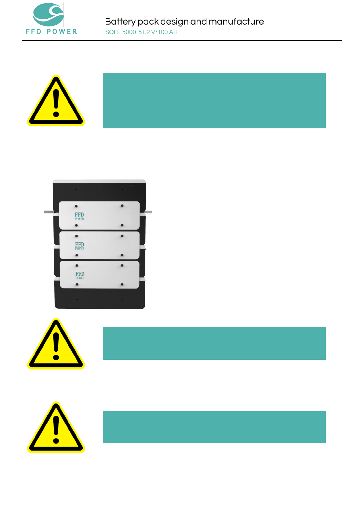
BATTERY OVERVIEW:
INFORMATION provides tips that are valuable for optimum installation and operation of the product.
SOC LED
Power button
Setting Screen
Removable cable installation handle
Removable connector cover
Wall bracket
Fixed handle
Cable Cover

Safety
Warnings and Notifications
Installation environment requirements: The FFD Module SOLE 5000 Stackable Battery Module is designed for
household/commercial purposes. For installation, it must be installed in a location complying with IP20
(IP 55 or 65 are available on request). Installations in locations that do not comply with IP20 may cause
failure and/or damage to the product, in which case the product warranty will become void.
Safety Guidelines
Caution
Adequately insulated tools up to 1500V shall be used at all times to ensure battery terminals are not short circuited. All
electrical connections on the FFD Module SOLE 5000 Battery Module shall be made only by qualified personnel.
When installed and operated in accordance with this manual, the FFD Module SOLE 5000 Battery Module will perform
in a safe and reliable manner in accordance with the battery operating specifications.
Subjecting the battery to an unsuitable operating environment or to damage, misuse or abuse may result in health and
safety risks such as overheating or electrolyte smoke potential. All personnel must comply with the safety precautions and
observe all warnings as detailed in this document. If any of the safety precautions or procedures detailed in this manual
are not fully understood by the reader, the reader must not perform any operation on the battery until they have contacted
the FFD MODULE technical service representative for clarification and confirmation of understanding of the correct
procedure.
The safety guidelines included in this document may not include or consider all the regulations in your area of installa-
tion/operation. When installing and operating this product, the installer must review and consider applicable Federal,
State and Local laws and regulations in accordance with the industry standards of the product.
Installation personnel shall not wear metallic objects, such as watches, jewelry and other metal items when performing
installations. Do not store un-insulated tools in pockets or tool belt while working in vicinity of battery to avoid short
circuits and personal injuries.
Caution
The weight of an individual FFD Module SOLE 5000 Battery Module is 126.3 lb / 57.3 kg.
Please use original packaging and follow all safety precautions if the Battery Module is to be relocated to another loca-
tion, to avoid damage to the product and personal injury.

General preparation
Before Installation:
Ensure that all the modules are turned OFF.
Battery installation location should be at least 20m away from sources of heat, sparks or other sources of extreme temper-
ature. Battery connecting cables shall be as short as possible to prevent excessive voltage drops.
Batteries with different capacity, different type/model or design or from different manufacturers shall not be connected
together.
1.Before connecting the battery, the battery positive and negative poles shall be carefully checked to ensure correct instal-
lation.
2.The installation location must be on a flat level surface, in a dry, clean and protected room, away from water and hu-
midity.
Before starting any operation on the battery, make sure to position the modules in their final position and structurally fix
all the modules that make up the system.
Wall/Floor mounted
With bracket and cable cover
Stack mounted
Without bracket and cable cover
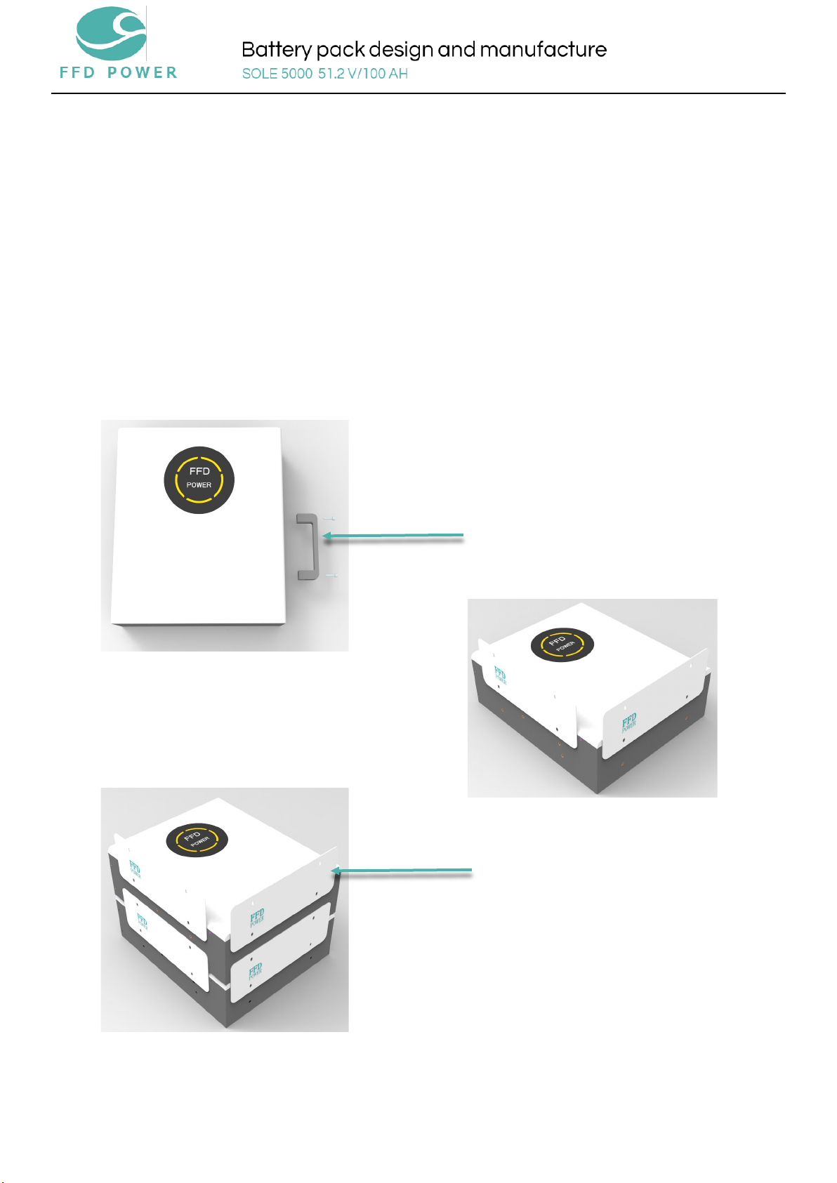
STACKABLE INSTALLATION INFORMATION
The stack configuration shall be concluded by interlocking the modules by using the Stopper/ Retainer plate as shown
below:
Step 1> Install the removable handle on the lower battery module ,Position the lower battery module on the selected in-
stallation position
Step2 > Take away the removable handle and fix Stopper / Retainer plate on the bottom and left side of lower battery
module
Sep3> Position the second battery module on the face of lower battery module with removable handle
Sep4> Remove the left removable handle of second battery module and regulate its position to fix Stopper/Retainer plate
with screw , then take away removable handle on the right side of second battery module
Stopper and Retainer
Removable handle

STORAGE & PRE-OPERATIONAL PROCEDURES
1.1 Storage - Transportation – Removing / Relocation of Batteries
This Battery is considered DANGEROUS GOODS by the United Nations and must be treated accordingly.
Each box comes from the factory with the below labels:
This battery can only be transported and stored with the original approved carton box, Certified as per UN
CLASS 9 Y80.
This Battery must be stored in its original carton box in a dry and cool place.
• The transportation and Storage State of Charge (SoC) shall not exceed 50%.
• The shelf period without recharging is 6 months, and then requires a quick charge up to 70% DoD and
discharge back to 50% at 0.5C / 77°F (25°C).
• To preserve the performance and shelf life, this battery should optimally be stored at 77°F (25°F) and
@70% humidity.
• Acceptable storage temperature range of the battery is between +59°F and +95°F (+15°C and +35°C).
• The self-discharge in the range of +59°F to +119°F (+15°C to +35°C) is around 1% a month. Any-
thing outside this range could exceed 10% a month.
• Do not store the batteries near sources of heat, vapor, gas, fuels, sparks or anything that could generate
fire or explosion.
• Store inside and protect from water and moisture.
• Transportation of new and used or damaged modules must be in accordance with the UN 38.3 Regula-
tion and with the Federal, State and Local regulations.
• If one or more working Battery Modules need to be removed or relocated, they must be marked as
USED BATTERY (follow local rules).
• If one or more Battery Modules need to be replaced due to damage, they should be marked as DAM-
AGED USED BATTERY and follow any applicable procedures and all Federal, State and Local regu-
lations.
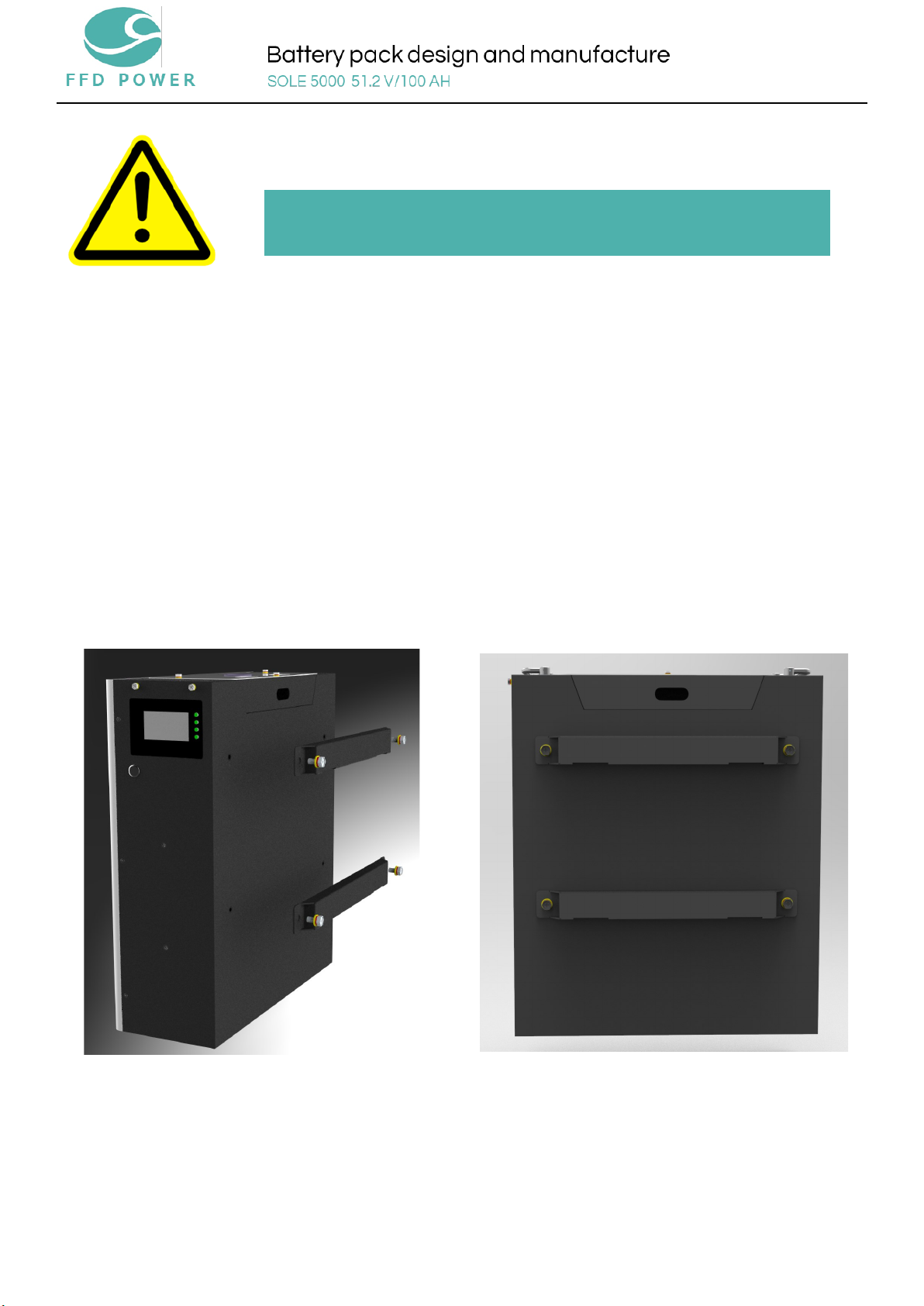
1.2 Module Unpacking and Handling
The battery is always delivered in WALL mode and it is therefore necessary for the installer to make sim-
ple changes to install the STACK kit. Below are the installation phases.
The battery must be lifted by four persons, using the four handles.
Two handles are built in and the other two are provided as temporary handles to be used as shown below.
Open the carton box, find the portable and retractable handles, position them and proceed with lifting.
Built in handle
Install Removable handle

1.2.1 Package Information and System Configuration List
The battery box is packed in cartons with accessories. Upon receipt, review the configuration list carefully to make sure
that the battery box and accessories are received in the correct quantities and type, and visually inspect to ensure that they
are free from damage. Refer to Section 2.1.3 for Low Voltage packing list . If battery is damaged and/or components
missing, contact your local FFD POWER representative
1.3 Wall Mount or Stack Mount Configuration
NOTE: The FFD Module SOLE 5000 Battery Module ships as standard in the wall
mount configuration
1.3.1 Battery Dimensions (Wall Bracket)
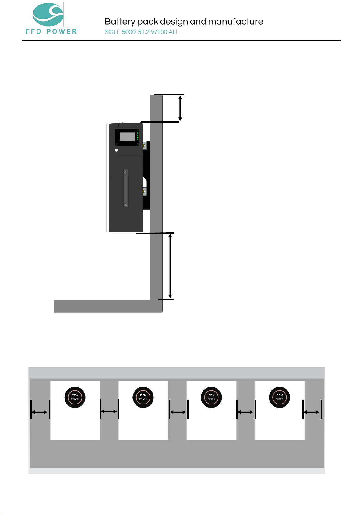
1.3.2 Wall Mount
Step 1: Install the wall bracket by using the wall plugs and screws contained in the battery kit. The wall must be inspected
before proceeding with the bracket installation. A local civil engineer should assess the correct installation method, either
wall mounted or floor mounted.
532mm
176mm 443mm
396mm
176mm
521mm
100-120 cm
The Battery Module weighs 126.3 lb /57.3 kg and must be installed with the help of
a mechanical lift, and/or with at least two people equipped with suitable suction
The Bracket must be installed on a flat and vertical wall.
The steel bracket must be flush to the wall without any empty spaces between the wall surface and the back side of the
bracket. Make sure to have adequate space to install the battery before proceeding with the installation.
Step 2: Install the back-side wall support plate using an cross point screwdriver. The plate has 4 screws
Step 3: Install the battery by fitting the back bracket of the module with the wall bracket interlocking. This operation must
be conducted with a mechanical lifting device and/or with at least two specialized installers. Make sure the Battery Mod-
ule is stable and properly locked into the upper interlocking plug.
Max . Height from bottom to floor 60-80cm(suggested
battery heights)
30 cm (min distance from the ceiling)
Step 2A: In case of multiple module installation, make sure to respect the distance between the modules and the ceiling.
25CM 25CM 25CM25CM 25CM
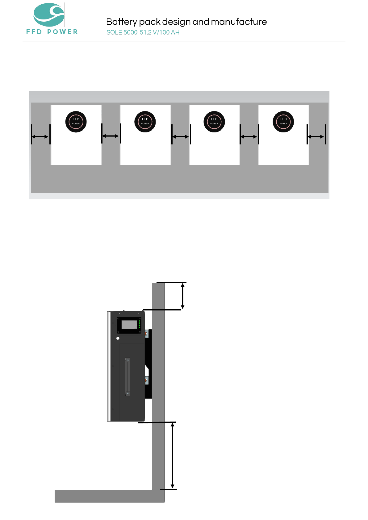
Step 2A: In case of multiple module installation, make sure to respect the distance between the modules and the ceiling.
25CM 25CM 25CM25CM 25CM
Step 3: Install the battery by fitting the back bracket of the module with the wall bracket interlocking. This operation must
be conducted with a mechanical lifting device and/or with at least two specialized installers. Make sure the Battery Mod-
ule is stable and properly locked into the upper interlocking plug.
Max . Height from bottom to floor 60-80cm(suggested
battery heights)
30 cm (min distance from the ceiling)
1.3.3 Stack Mount
The Battery Module weighs 126.3 lb /57.3 kg and must be installed with the help of
a mechanical lift, and/or with at least two people equipped with suitable suction
cups for mechanical lifting or lifting straps. As previously stated in this manual, the
SOLE 5000 Battery Module comes as standard in wall mount configuration. To
install in the Stackable configuration
1. Start stacking the second module on top of the first module laid on the ground by using the side removable handles.
In case of horizontal installation, the installer must prepare an adequate distribution plate on the floor in order to make a
safe and stable support for the battery stack
Before stacking the batteries, the installer must check the maximum permissible
floor load. It is recommended that the installer obtains approval from a civil engi-
neer
Ensure the support and/or the floor surface is adequate to support the battery load
1 module : 50 KG
2 modules: 100 KG
3 modules : 150 KG
4 modules : 200 KG

1.4 Battery Terminal Function Definition
1234
56789
12
1110
INTERFACE NAME FUNCTION
1A+ POSITIVE (+) Quick connector
2B+ POSITIVE (+) Quick connector
3A-NEGATIVE (-) Quick connector
4B-NEGATIVE (-) Quick connector
5RS485-BCOMMUNICATION PORT RS485
6PARALLEL COMMUNICATION PORT CAN
7RS232 COMMUNICATION PORT RS232
8RS485-ACOMMUNICATION PORT RS485
9CAN COMMUNICATION PORT CAN
10 DIP SWITCH DIP SWITCH Address HUB 6 PINS
11 RST Reset button
12 ON/OF ON/OF Pilot light
13 RUN RUN Pilot light
14 ALARM ALARM Pilot light
15 DRY CONTACS Dry Contacts Terminal
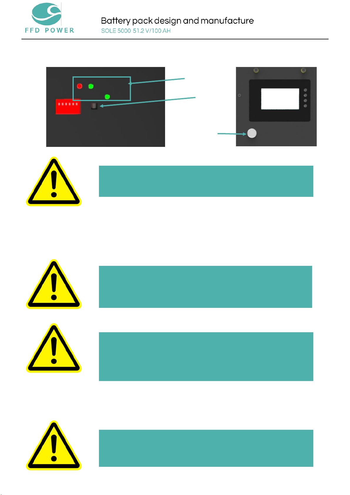
1.5 Out of the Box Pre-Operational Check
Attention: Do not make any connection to the Battery Module until you have thor-
oughly read and understood this entire manual
The Power Button is located on the right side of the Battery Module as shown above. Pressing the Power Button will initiate the
startup process of the battery. Press reset button with Pin , battery begins to work , three pilot lights turn on one by one , from
left to right , when all the 3 pilot lights turn on, then they turn off together . If the red color light (Alarm) remains on , there is a
fault, and you should not attempt any further operation of the battery but contact FFD POWER Module support at ser-
ATTENTION: Before Operating make sure that the voltage is equal to 0 Vdc Bat-
tery must be turned off before starting any activity
Attention: At this stage, after you have determined that the battery is functioning
correctly, it is mandatory to switch the battery off and follow the instructions and
guidance in this manual very carefully before attempting any configuration or con-
nection to the Battery Module.
To switch the battery off (shutdown the battery), simply press Start/Stop button for 5-seconds and the green LED light
will go off, confirming that the battery has shutdown correctly
Attention: Read this manual thoroughly, and always follow the guidance herein
before and while performing any installation procedure.
Power button
Reset button
Pilot lights

2.1 Product Introduction
The FFD Module SOLE 5000 Battery Modules can be used as an on-grid or off-grid energy storage system. It is not rec-
ommended to use this product for any purpose other than the intended purpose as described in this document.
• Use of this product other than as described in this document will nullify the product warranty.
• The substitution of any components of this Battery Module will nullify the product warranty.
• The use of any components contained within or connected to this Battery Module other than the products sold as part
of this product or recommended by the manufacturer will nullify the product warranty.
• Connecting more than 16 FFD SOLE 5000 Battery Modules in parallel will nullify the product warranty.
2.1.1 Identifying the Individual Module
Module dimension mm 520L*443W*136H
Weight kg 50
Case material Type Steel
Parallel modules Max. No. 16
Stackable Type Yes
Digital output Type CAN / RS485
Cell Distribution P/S 16S
Cell Type Type LiFePO4
BMS charge temp °C 0--55
BMS Discharge Temp °C -20--55
Suggested Storage Temp °C -10--45
Recharge time @ Suggested Stor-
age Temp
Month 3 month
Self-Discharge @ 25°C %1% per month
Self-Discharge outside the STC % 3% per month

Product Identification and labels
The nameplate label describes the product parameters and is attached to the product. For details, please refer to the name-
plate label of the product. For safety reasons, the installer must have a thorough understanding of the contents of this man-
ual before installing the product .
FFD POWER
FFD POWER TECH CO., LTD Room 308 ,Xintian Street 70 ,Xintian District ,Fuhai ,Baoan ,Shenzhen
Emergency No. +86 13377773990
Model SOLE 5000
Nominal Capacity @ Standard Test Condi-
tions
100AH
Cell type LiFePO4 (lithium iron phosphate)
Nominal voltage 51.2VDC
Overcharge Protection Voltage 57.92VDC
Over-Discharge Protection Voltage 41.60V
Overcharge Protection current 100A
Over-Discharge Protection current 150A
Parallel Units 16 Units
IP Grade IP 21
Weight 50KG
Standards IEC 62619
CE
IEC 6100-3-3:2013+A1:2019
EN6100-6-3:2007/A1:2011/AC:2012
IEC 6100-3-2:2019+A1:2021
UN Test Approved IEC 6100-3-3:2013+A1:2019
Good Class Dangerous Goods DG9 Category 3480
Production Date DD/MM/YYYY
This battery must be installed and maintained by qualified professional
Installers , Read warranty terms and conditions before use; improper use
and installation will void the arranty
EAN BAR CODE EXAMPLE
Compliant with UN38.3 Cert Number UN2021-1999-1 and SDS for sea safe transportation Cert Number
Table of contents


